

Page 1
INSTALLATION AND MAINTENANCE INSTRUCTIONS
I56-3381-003
RTS2, RTS2-AOS, AOS
Multi-Signaling Accessory
SPECIFICATIONS
Dimensions: 4.8"W x 5.3"H x 1.6"D (12.2cm W x 11.9 cm H x 3.8 cm D)
Weight: 0.35 lb. (160 g)
Operating Voltage: 20-29 VDC
Power Requirements
Standby: 3.0 mA max.
Trouble: 16.0 mA max
Alarm w/o strobe: 30 mA max
Alarm with strobe: 55 mA max
Connections: Strip terminal, 14 AWG to 22 AWG wire
Wiring Distance: 1000 Feet From Duct Smoke Detector
Sounder: 85 dBA at ten feet
Temperature: 14°F to 140°F (-10°C to 60°C)
Humidity: 95% relative humidity; non-condensing
Listing: UL 268 and ULC S529-02
Notice: This manual should be left with the owner/user of this equipment.
GENERAL INFORMATION
The National Fire Protection Association (NFPA) has published codes, standards, and recommended practices for the installation and use of this product.
It is recommended that the installer be familiar with theses requirements, with
local codes, and any special requirements of the local authority having jurisdiction. For further information, consult NFPA 72 and 90A requirements.
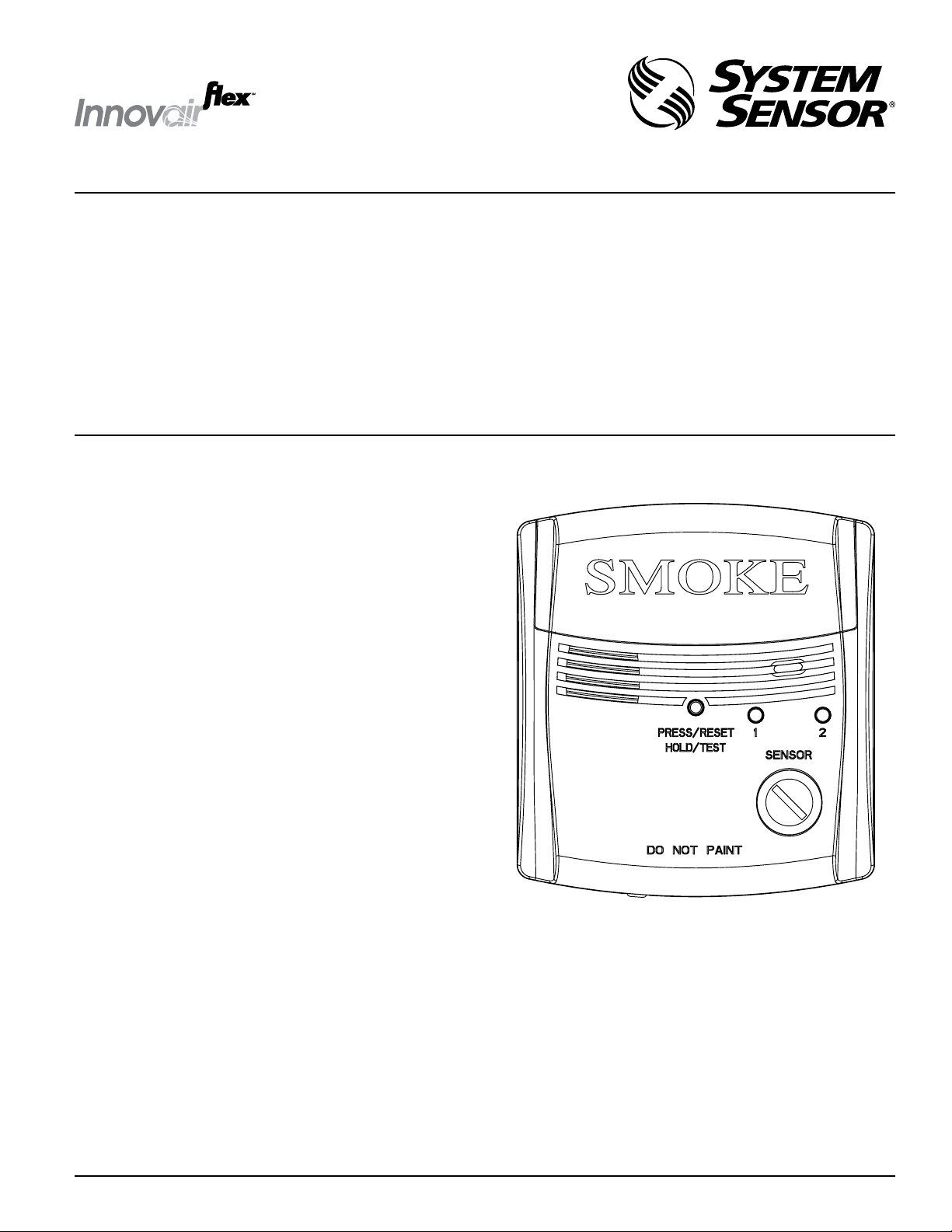
The System Sensor RTS2 and RTS2-AOS multi-signaling accessories are designed for use with System Sensor InnovairFlex 4-wire conventional duct
smoke detectors only. The accessory has two bicolored LEDs that indicate the
sensor status of up to two connected duct smoke detectors. The key switch
on the unit can be used to select a connected duct detector sensor (either sensor 1 or sensor 2), and the selected sensor can be tested or both sensors can
be reset simultaneously using the test/reset button. LED status indications
include: Standby (green blink), Trouble (amber), Maintenance (amber blink)
and Alarm (red).
With the key switch selected, there is also the capability of obtaining a sensitivity measurement of the selected sensor using the SENS-RDR sensitivity
reader (sold separately).
SPECIFIC FEATURES OF THE RTS2 AND RTS2-AOS INCLUDE:
• Standby (Green Blink), Trouble (Amber), Maintenance (Amber Blink)
and Alarm (Red) LEDs to indicate detector status
• Keyswitch to select desired sensor, enable test/reset button and
sensitivity reading
• Test/reset button
• Sensitivity reading ability with SENS-RDR (sold separately)
• Selectable continuous or temporal tone
• AOS-Add-On-Strobe (included on RTS2-AOS model)
• Provisions for single- or double-gang box mounting
• Ability to discretely monitor two sensors when duct smoke detectors
are configured in a 2-to-1 set up (See InnovairFlex duct smoke detector
manual for reference.)
CONTENTS
1 RTS2 or RTS2-AOS Multi-Signaling Accessory
1 Mounting Hardware Kit (Contains (2) sets of mounting screws and (1) tamper resistant outer cover mounting screw.
FIGURE 1:
3825 Ohio Avenue, St. Charles, Illinois 60174
1-800-SENSOR2, FAX: 630-377-6495
www.systemsensor.com
H0621-00
SS-310-00 1 I56-3381-003
Page 2
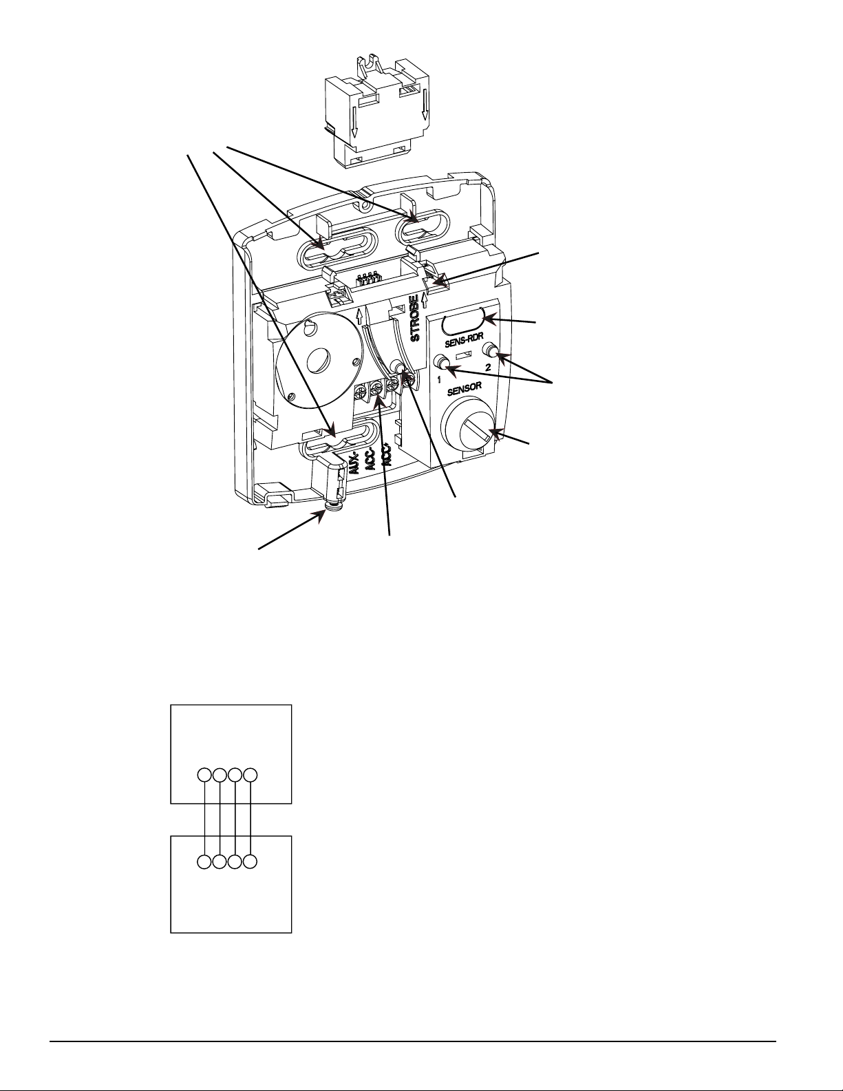
FIGURE 2:
SINGLE/DOUBLE-GANG
MOUNTING
AOS Add-On-Strobe
•SOLD SEPERATELY or
Included on RTS2-AOS
(Remove for Continuous pattern)
SENSITIVITY READER
TEMPORAL JUMPER
LOCATION
LEDs
SELECTOR
KEY SWITCH
FIGURE 3: WIRING DIAGRAM
D4120/D4120W/D4P120
NOTE: If polarity of Acc. (+) and Acc. (—) are reversed,
an Amber LED on sensor 2 of the duct smoke detector
power board will exist indicating a trouble condition.
OUTER COVER
LOCKING SCREW
RTS2/RTS2-AOS
AUX
AUX
ACC
ACC
(-)
(-)
(-)
AUX
(-)
ACC
(+)
(+)
ACC
(+)
(+)
AUX
TEST/RESET
BUTTON
H0624-00
(4) TERMINALS
INSTALLATION
Installing the Mounting Plate
1. Secure the mounting plate to a single- or double-gang electrical box with
(2) mounting screws provided. Note: If mounting to a single-gang box, the
Add-On Strobe (AOS) must be removed prior to mounting. To remove the
AOS, squeeze opposing sides lightly next to arrows and slide vertically.
2. If applicable, install the AOS onto the mounting plate as shown in Figure 2.
Note, the RTS-AOS includes the AOS.
NOTE: installation per ULC S524-02
Temporal Sounder
The RTS2 accessory provides the option of sounding a continuous or temporal
pattern. The RTS2 will default to sound in a temporal pattern. For a continuous pattern, remove the jumper located just to the right of the “Strobe” text on
the mounting plate as shown in Figure 2.
WIRING
Wire the RTS2 as shown in Figure 3, for InnovairFlex 4-wire conventional duct
smoke detectors. Limit wire runs to 25 ohms or less per interconnecting wire.
NOTE:
1. If polarity of Acc. (+) and Acc. ( —) are reversed, an Amber LED on sensor
2 of the duct smoke detector power board will exist indicating a trouble
condition.
2. One RTS2 can be wired to only one InnovairFlex power board.
3. If Aux. (+) and Aux. (—) wires are reversed, the strobe and sounder will
not function.
Installing the Outer Cover
1.Install the outer cover on the mounting plate by sliding the outer cover over
the upper tabs of the mounting plate as shown in Figures 4 and 5.
2.Tighten the outer cover mounting screw located at the bottom of the device.
H0626-00
Note: The mounting screw can be replaced with the provided tamper resistant
Torx screw, if desired.
SS-310-00 2 I56-3381-003
Page 3

OPERATION
The green “Standby” will blink every 5 seconds whenever the duct smoke
detector is receiving power. The amber “Trouble” LED is lit when the duct
smoke detector sensor is missing or the detector cover is removed. The delay
to indicate a trouble condition once the cover is removed depends on the dip
switch setting on the duct smoke detector power board. An LED with amber
blink every 5 seconds indicates that the sensor is in “Maintenance” which indicates that the sensor needs to be cleaned or replaced. See Table 1 LED Status
Indication for a detailed list of indications.
ENABLING THE TEST/RESET/SENSITIVITY OPERATION
Insert the key and turn to select either sensor 1 or 2. This will enable the
selected sensor to be tested, reset, or sensitivity read. Note all test/reset/sensitivity functions can be initiated with the outer cover installed or directly on
the mounting plate.
TEST FUNCTION
With the desired sensor selected by the key, press and hold the Test/Reset button for 2 seconds. If the sensor is within its sensitivity limits, the device will
alarm within the next 3 seconds. The RTS2 will not initiate a test condition if
a trouble exists on D4120.
ALARM INDICATION
Once the Test/Reset button has been pressed, the red alarm LED will illuminate and the horn will sound (within 5 seconds). If an AOS (add-on strobe) is
installed, it will flash.
RESET FUNCTION
Reset is a common function to both sensors. Press and release the Test/Reset
Button. The red alarm LED should turn off on both sensor LEDs and the horn
will cease sounding. The strobe will cease flashing (if optioned). The current
sensor status will be indicated (See Table 1). Note, the key switch must still be
selected for one of the sensors in order for the reset function to be enabled.
SENSITIVITY FUNCTION
When the key is installed and sensor 1 or 2 is selected, the selected sensor
sensitivity can be read via a SENS-RDR (sold separately).
1. Select the desired sensor with the key.
2. Press the test button on the SENS-RDR. “Ready” should appear on the
SENS-RDR display.
3. Hold the SENS-RDR up to the oval indentation on the mounting plate or
outer cover (if installed). Within 10 seconds the sensor sensitivity will be
displayed.
DISABLING THE TEST/RESET/SENSITIVITY OPERATION
When the key switch is returned to the neutral (vertical) position and
removed, the Test/Reset button will be disabled.
TABLE 1: LED STATUS INDICATIONS
Mode Indication
Off LEDs off
Initialization Green/Amber blink
Normal Green blink
Maintenance Amber blink
Communication Error Amber long blink
Trouble Solid Amber
Alarm Solid Red
FIGURE 4:
H0623-00
FIGURE 5:
* Please note that the mode of the LEDs on the RTS2 represent the mode of the
respective sensors connected to the InnovairFlex duct power board.
** Refer to the InnovairFlex installation and maitenance instructions for
additional LED/Status details.
H0625-00
SS-310-00 3 I56-3381-003
Page 4

ORDERING INFORMATION
RTS2 Multi-Signaling Accessory
RTS2-AOS
AOS Add-On Strobe
RTS2/ AOS
RTS2-AOS
Multi-Signaling Accessory
with Strobe
INNOVAIRFLEX DUCT SMOKE DETECTORS
UL ULC DESCRIPTION
D4120 D4120(A)
D4120W Not Listed
D4P120 D4P120
D4S D4S
4-Wire Photoelectric Duct
Smoke Detector
4-Wire Watertight Duct
Smoke Detector
4-Wire Power Board-Only
Component
4-Wire Photoelectric
Additional Sensor
OTHER ACCESSORIES
UL ULC DESCRIPTION
RTS151 Not Listed Remote Test/Reset Station
RTS151KEY RTS151KEY(A)
Key-Activated Remote Test/
Reset Station
APA151 Not Listed Piezo Annunciator
RA100Z RA100Z(A) Remote Annunciator Alarm
SENS-RDR Not Listed Sensitivity Reader
H0196-01
SENSOR UNIT
H0621-00
H0195-01
H0627-00
POWER BOARD UNIT
H0614-02
A0360-01
WARNING
The sounder or sounder/strobe combination will not operate if the power is
cut off for any reason.
If power is cut off for any reason, the sounder or strobe/sounder combination
will not provide the desired audible or visual warning.
The sounder may not be heard. The loudness of the sounder meets or exceeds
the current Underwriters Laboratories’ standards. However, the sounder may
not alert a sound sleeper or one who has recently used drugs or has been
drinking alcoholic beverages. This sounder may not be heard if it is placed in
an area that is separated by a closed door, or if it is located on a different floor
from the person in a hazardous situation, or if it is placed too far to be heard
over ambient noise, such as, traffic, air conditioners, machinery or musical
appliances that may prevent alert persons from hearing the alarm. For these
The Sounder and add-on strobe are for supplemental signaling only.
The signal strobe may not be seen. The visual warning signal is suitable for
direct viewing and must be installed within an area where it can be seen by
building occupants. The strobe must not be installed in direct sunlight or areas of high light intensity where the visual flash might be disregarded or not
seen.
The strobe may not be seen by the visually impaired.
The signal strobe may cause seizures. Individuals who have a positive photic
response to visual stimuli with seizure, such as epileptics, should avoid prolonged exposure to environments in which strobe signals, including this
strobe, are activated.
reasons, System Sensor recommends that sounders (85dBA minimum at 10
feet) used in a residence shall be placed on every level and in every bedroom
that does not have a smoke detector with a built-in sounder.)
The sounder may not be heard by persons who are hearing-impaired. In this
case, a visual indicator shall also be used.
THREE-YEAR LIMITED WARRANTY
System Sensor warrants its enclosed product to be free from defects in materials and
workmanship under normal use and service for a period of three years from date of
manufacture. System Sensor makes no other express warranty for the enclosed product.
No agent, representative, dealer, or employee of the Company has the authority to increase or alter the obligations or limitations of this Warranty. The Company’s obligation
of this Warranty shall be limited to the replacement of any part of the product which
is found to be defective in materials or workmanship under normal use and service
during the three year period commencing with the date of manufacture. After phoning
System Sensor’s toll free number 800-SENSOR2 (736-7672) for a Return Authorization
number, send defective units postage prepaid to: System Sensor, Returns Department, RA
#__________, 3825 Ohio Avenue, St. Charles, IL 60174. Please include a note describing
the malfunction and suspected cause of failure. The Company shall not be obligated to
replace units which are found to be defective because of damage, unreasonable use,
modifications, or alterations occurring after the date of manufacture. In no case shall the
Company be liable for any consequential or incidental damages for breach of this or any
other Warranty, expressed or implied whatsoever, even if the loss or damage is caused by
the Company’s negligence or fault. Some states do not allow the exclusion or limitation of
incidental or consequential damages, so the above limitation or exclusion may not apply
to you. This Warranty gives you specific legal rights, and you may also have other rights
which vary from state to state.
SS-310-00 4 I56-3381-003
©2009 System Sensor
 Loading...