

Page 1
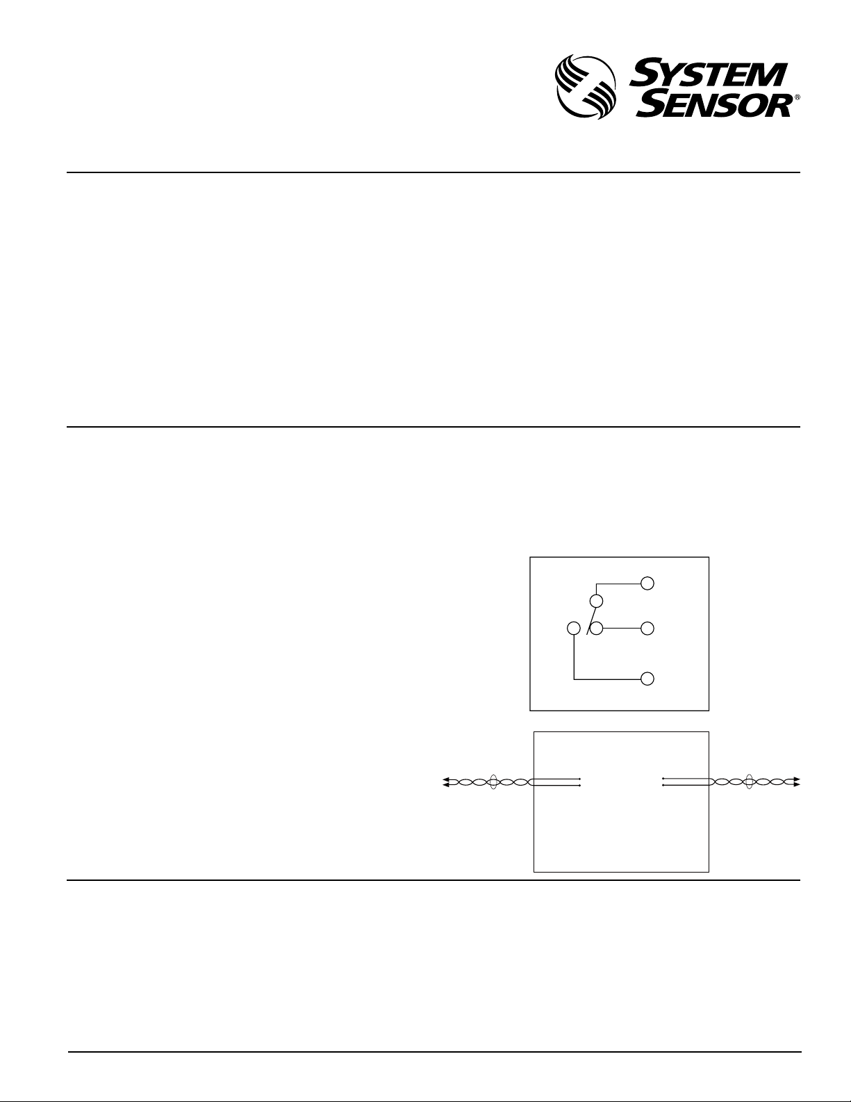
YELLOW
BLUE
ORANGE
–
+
–
+
Non-Power
Limited
Power
Limited
Blue Wire
Yellow Wire
Orange Wire
Red Wire
Black Wire
White Wire
INSTALLATION AND MAINTENANCE INSTRUCTIONS
I56-2191-007
PR-1
Multi-Voltage Relay
Specifications
Operating Voltage: 18-35 VDC, 18-35 VAC, 120 VAC
Operating Current: 15 mA max.
Operating Temperature Range: –40ºF to 158ºF (–40ºC to 70ºC)
Storage Temperature Range: –58ºF to 185ºF (–50ºC to 85ºC)
Humidity: 10 to 93% RH non-condensing
Wire Length: 8
Dimensions: 0.87˝H x 2.01
(22 mm H x 51 mm W x 36 mm D)
Accessories: Six wire nuts
One piece of double sided tape
One 1
Contact Ratings: 24 VDC 7A
120 VAC 7A max. (0.35 PF)
250 VAC 10A max. (resistive load)
30 VDC 10A max. (resistive load)
NOTICE: This manual should be left with the owner/user of
this equipment.
General Description
Model PR-1 is an epoxy encapsulated single pull double throw
(SPDT) relay. The PR-1 also uses a red LED as a visible indication
of relay coil energization.
Mounting
For ease of installation, the PR-1 relay may be mounted in a variety of ways. It can be attached within compatible equipment
or in a separate enclosure using a mounting screw. Double sided
tape is also provided for additional support.
Wiring
NOTE: All wiring must conform to applicable local codes, ordinances, and regulations.
The PR-1 connections are shown on the label on the side of the
relay. Using the enclosed wire nuts, secure the electrical connections appropriate to the application. Provisions must be taken to
separate power limited and non-power limited wiring per National
Electrical Code requirements. Field installable wiring connected
to the product must have a minimum 1/4 inch spacing between
the power limited and non-power limited wire.
NOTE: There is high voltage running through the red wire. To
help prevent injury, put a wire nut on the red wire before installing. This is only applicable when using 120 VAC operating voltage
(black wire).
˝ min. (203 mm)
˝W x 1.42˝D
1
/4˝ screw
WIRE DEFINITIONS
RED POWER INPUT 24 VDC (+)/24 VAC
BLACK POWER INPUT 120 VAC
BLUE RELAY - COMMON
YELLOW RELAY - NORMALLY CLOSED
ORANGE RELAY - NORMALLY OPEN
WHITE POWER INPUT 24 VDC(–)/24 VAC/120 VAC
3825 Ohio Avenue, St. Charles, Illinois 60174
1-800-SENSOR2, FAX: 630-377-6495
www.systemsensor.com
C0209-00
C0899-00
Three-Year Limited Warranty
System Sensor warrants its enclosed product to be free from defects in
materials and workmanship under normal use and service for a period
of three years from date of manufacture. System Sensor makes no other
express warranty for the enclosed product. No agent, representative,
dealer, or employee of the Company has the authority to increase or alter
the obligations or limitations of this Warranty. The Company’s obligation of this Warranty shall be limited to the replacement of any part of
the product which is found to be defective in materials or workmanship under normal use and service during the three year period commencing with the date of manufacture. After phoning System Sensor’s
toll free number 800-SENSOR2 (736-7672) for a Return Authorization
number, send defective units postage prepaid to: System Sensor, Returns
D140-04-00 1 I56-2191-007
© 2006 System Sensor
Department, RA #__________, 3825 Ohio Avenue, St. Charles, IL 60174.
Please include a note describing the malfunction and suspected cause
of failure. The Company shall not be obligated to replace units which
are found to be defective because of damage, unreasonable use, modifications, or alterations occurring after the date of manufacture. In no
case shall the Company be liable for any consequential or incidental
damages for breach of this or any other Warranty, expressed or implied
whatsoever, even if the loss or damage is caused by the Company’s
negligence or fault. Some states do not allow the exclusion or limitation of incidental or consequential damages, so the above limitation or
exclusion may not apply to you. This Warranty gives you specific legal
rights, and you may also have other rights which vary from state to state.
 Loading...