

Page 1

Aspirating Smoke Detector
Pipe Installation
USER GUIDE
Page 2

Table of Contents
User Guide: Aspirating Smoke Detector Pipe Installation
Scope of this user guide ............................... 3
Designing a Pipe Network ............................3
Pipe Overview ................................................4
Pipe Network Components ............................................ 4
Pipes ..............................................................................4
Pipe Temperature...........................................................4
Fittings ............................................................ 4
Couplings and Unions ................................................... 4
Elbows ...........................................................................4
Tees ................................................................................4
End Caps ....................................................................... 5
Capillary Tubes and Sampling Ports ............................. 5
Mounting Brackets ......................................................... 5
Labels ............................................................................5
Pipe Network Installation .............................. 6
Sampling Methods ....................................... 11
Standard Pipe Network Sampling ...............................11
Capillary Tube Sampling .............................................11
Open Area Protection .................................. 12
Ceiling Sampling .........................................................12
Inter-Beam / Below-Beam Sampling ...........................13
Under Floor Protection ................................ 13
Floor Void Sampling .....................................................13
Object Protection ......................................... 14
Cabinet Sampling ........................................................14
In-Cabinet Sampling ....................................................14
Above-Cabinet Sampling ............................................14
Large Area Protection ................................. 15
Cold Area Protection ................................... 15
High Air Exchange Areas ............................ 16
Cutting Pipe ...................................................................6
Joining Components ...................................................... 6
Mounting the Pipe Network ...........................................6
Pipe Bends ....................................................................6
Drilling Sample Ports .....................................................7
Installation Stages..........................................................7
Application and Design ................................. 8
Design ............................................................................ 8
Regulatory Requirements .............................................. 9
Site Layouts and Measurements .................................10
Site Details ...................................................................10
Environmental Conditions ............................................10
System Design .............................................................10
Return Air Sampling .....................................................16
In-Duct Sampling ......................................... 17
Design Considerations for In-Duct Sampling ..............17
Small Duct Sampling ...................................................17
Large Duct Sampling ...................................................18
Port Orientation ............................................................ 18
Monitoring Voids .......................................... 18
Basic Pipe Cleaning & Maintenance .......... 19
Pipe Network Maintenance .........................................19
Filter Maintenance .......................................................19
22
Page 3

User Guide: Aspirating Smoke Detector Pipe Installation
Scope of this user guide
The purpose of this user guide is to provide details on the physical installation of the pipe network for the FAAST Fire Alarm Aspiration
Sensing Technology® aspirating smoke detector. Local codes and regulations may vary and take precedence over the information
contained in this user guide.
Designing a Pipe Network
The FAAST detector and its pipe network allow deployment of smoke detection in challenging and mission critical environments. In
order to ensure the system will operate in accordance to site specific requirements, as well as local codes and regulations, the pipe
network must be designed and verified using the PipeIQ® software. PipeIQ can be downloaded at systemsensor.com/faast.
3
Page 4
User Guide: Aspirating Smoke Detector Pipe Installation
Pipe Overview
Pipe Network Components
The FAAST detector uses standard aspiration fire detection pipe
network components, such as pipes, elbows and couplings.
The components listed in this section are not an all inclusive list,
however they represent the most commonly used items.
Pipes
The pipes used in the pipe network can be made of various
materials including copper, PVC, ABS, UPVC and CPVC. The
internal pipe diameter used with the FAAST system can range
from 0.591" to 0.827" (15 to 21 mm). Ideal dimensions vary
depending on system design requirements as well as local
codes and regulations. The FAAST detector has a built in tiered
insertion point for the pipes which allows for an outside tube
diameter of either 1.050" or 25 mm to accommodate U.S.
Customary System and Metric System Sized Pipes.
Frequently Asked Question – Can we use metal pipe instead
of plastic with FAAST?
Yes. It is acceptable to use either steel or copper pipe under the
following conditions:
Fittings
Fittings are used to connect sections of pipe together on longer
network runs and are made from the same material as the pipe.
There are several types of fittings to allow for various bends,
straight runs, branches and connections. Common fittings are
described in the following sections.
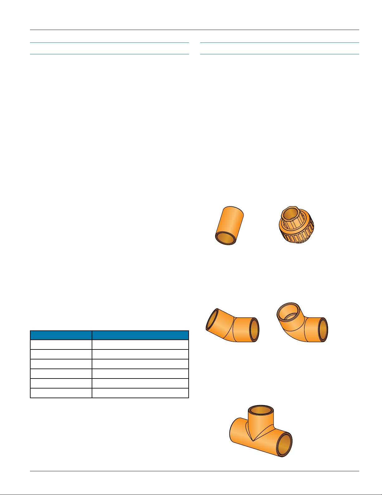
Couplings and Unions
Couplings and unions are used to connect two sections of pipe
in a straight line. A coupling is used when the section is not
intended to be taken apart.
A union offers the ability to screw the two pipe sections together
for future access, such as areas of the pipe network that have
to be periodically disassembled for maintenance and cleaning.
Unions can also be used to orient sample ports correctly in
a specific section of the pipe network, such as over return
air grilles (for more information on high air flow and duct
applications, see the white paper at systemsensor.com/faast).
Figure 1 shows a typical union and coupling.
• The pipe size used must be capable of fitting to a plastic
pipe upon interfacing with the FAAST device. The inner
diameter must be within the approved range of
.591" - .827" ( 15.00 - 21.00 mm ).
• The material must be approved by the local authority
having jurisdiction and must also be approved by the
insurance underwriter
Pipe Temperature
Pipe selection may be contingent on the temperature of the
room in which the pipe will be mounted. Table 1 shows
temperature ranges for various types of pipe.
Pipe Material Service Temperature
ABS -40 – 80°C (-40 to 176°F)
PE-80 -50 to 60°C (-58 to 140°F)
PE-100 -50 to 60°C (-58 to 140°F)
CPVC -26 to 93°C (-15 to 200°F )
PVC -26 to 49°C (-15 to 120°F)
Copper -150 to 110°C (-238 to 230°F)
Table 1: Temperature ranges for various types of pipe.
ASP-76
Figure 1: Couplings and unions.
ASP-75
Elbows
Elbows are used to change the direction of the pipe network.
Both 45 degree and 90 degree elbows may be used. Both
elbow fittings are shown in figure 2.
45°
ASP-77 ASP-78
Figure 2: Elbows.
90°
Tees
Tees are also used for branching into multiple pipes from a
single pipe network. A specialized tee can be used to attach a
capillary tube and a sampling port. A tee is shown in figure 3.
* For specific design considerations in cold temperature
applications, download the Cold Storage White Paper from
systemsensor.com/faast
ASP-80
Figure 3: Tees
4
Page 5
User Guide: Aspirating Smoke Detector Pipe Installation
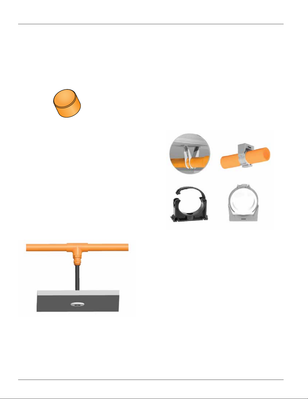
End Caps
The end of the pipe should be terminated with an end cap. The
end cap may have a sampling port depending on the system
design. The size of the port in the end cap is determined by the
PipeIQ software. An end cap is shown in figure 4.
ASP-79
Figure 4: End caps.
Capillary Tubes and Sampling Ports
A capillary tube is a length of flexible tubing that is connected
to the main sampling pipe with a sampling port at the end.
The purpose of these tubes is to extend the placement of the
area being sampled away from the main pipe network. This may
be necessary to reach in to an enclosed space, such as a
cabinet, or for aesthetic or security reasons. This allows the core
pipe network to be hidden while only a small sampling port is
located in the main space. Figure 5 shows the capillary tube extending down from the main sampling pipe with a sampling port
at the end. PipeIQ allows for capillary tubes and sampling ports
to be added to the pipe network design and will calculate the
appropriate air flow through the system.
Mounting Brackets
The pipe network is mounted to the ceiling, or other appropriate
location, using mounting brackets. A large variety of brackets
are available from a standard pipe supplier. Typical brackets
include clips, saddle clamps, or tie wraps, as shown in Figure 6.
The mounting choice will depend on the material being mounted
to, environmental temperature, and local codes and regulations. Mounting brackets are usually centered 5 ft. (1.5 m) apart
when using 3/4" schedule 40 pipe at 70°F (21°C). At 140°F this
spacing reduces to 2.5 ft. between support brackets. Open
style mounting clips should not be used in an inverted position
with the open section facing downward, because the pipe could
drop from the clip.
The maximum length for capillary flexible tubing is 26 ft. (8 m).
When multiple capillary tubes are used in a network, the length
of each capillary tube should be approximately equal.
ASP-83
Figure 5: Capillary tubes and sampling ports.
ASP-81
Figure 6: Mounting brackets.
Labels
Labels are available to identify the pipe network as a fire
detection system, both at the sampling ports and along the pipe
itself. NFPA 72® states that the pipe should be labeled:
1. At changes in direction or branches of piping
2. At each side of penetrations of walls, floors, or
other barriers
3. At intervals on piping that provide visibility, but no
greater than 20 ft. (6.1 m)
5
Page 6

Pipe Network Installation
User Guide: Aspirating Smoke Detector Pipe Installation
This section provides the basics to installing a pipe network.
Keep in mind that each system will have different characteristics, and will have variations to accommodate. The most
common issues are described in the following sections. To
ensure a pipe network performs as expected, it must be
designed in PipeIQ and installed as specified by the software.
Cutting Pipe
Proper tools must be used when cutting pipe. Pipe shears or a
wheel type plastic tubing cutter can be used for plastic pipe.
Always keep the cutting edge of the tools sharp. Ensure that
cuts are made perpendicular to the pipe length, keeping the
cuts square. Square cuts ensure maximum bonding area and
help provide a good seal when joining the components.
Remove all loose material and any burrs from the end of the
pipe after a cut. Debris and shavings from cuts must be removed in order to keep sampling ports free of obstruction.
Joining Components
The pipe network must be permanently connected once the
system has been installed and tested. The method to
accomplish a permanent connection depends upon the material
of the pipe and fittings.
NOTE: The immediate connections between the inlet pipe
and exhaust pipe and the FAAST detector SHOULD NOT be
permanently connected.
When bonding components together, never apply solvent on the
inside of a pipe or other component. Apply the solvent only to
the outside of the pipe that is being inserted into a coupling or
other component. If a solvent is applied to the inside of a pipe or
other component, the solvent can build up. This build up can
affect the air flow within the pipe network and may cause
abnormal behavior within the pipe network.
Make sure that pipes are inserted completely and butted
against the lip of the coupling or other component. If this is not
done, turbulence can be created due to the gaps, which can
cause problems with system pressures and air flow.
Frequently Asked Question – Is there a specic glue that
must be used when assembling the network piping?
Mounting the Pipe Network
The following recommendations should be taken into
consideration when mounting the pipe network.
• Minimize flexing of the pipes by securing them at proper
intervals with appropriate mounting brackets.
Maximum Support Spacing at Ambient Temperature
Pipe Diameter 60°F (16°C) 100°F (38°C) 140° F (60°C)
1/2 in. (15mm) 4.5 ft. (1.3 m) 4 ft. (1.2 m) 2.5 ft. (0.7 m)
3/4 in. (20 mm) 5 ft. (1.5 m) 4 ft. (1.2 m) 2.5 ft. (0.7 m)
Table 2: Maximum support spacing at ambient temperature.
• Typically, the pipe network should be mounted between
1 and 4 in. (25 – 100 mm), maximum of 12 in. (300 mm),
below the ceiling, subject to local codes and regulations.
• Allow for expansion and contraction of the pipe network in
areas of extreme temperature fluctuations, especially on
long straight pipe runs.
• In areas of extreme temperature fluctuations, never place
mounting brackets adjacent to couplings, unions or tees.
This can lead to interference with expansion or contraction
of the pipe network.
• To minimize the effect of pressure differentials that could
affect the air flow of the system, the sampled air must be
returned to the protected environment via exhaust tubing
wherever possible.
Pipe Bends
Never bend pipes unless absolutely necessary. Use elbows,
tees, or other fittings to change direction of the pipe.
If bending is necessary, determine how much bending the
pipe can tolerate before beginning the process. Always use
bending springs and pipe benders. Bending a pipe without heat
will cause the PVC to shatter. Never heat the pipe or bend it
around sharp objects. If a pipe creases or buckles while
bending, replace it with a new section of pipe. Conform to all
local codes and regulations for bending of pipes.
Yes, glue that is listed for the type of pipe used. When applying
the glue be cautious not to leave excess residue inside the pipe.
This can trap dust or dirt particles that can possibly affect the
airflow of the detector over time.
Prior to drilling any sample ports, the pipe network should be
checked for leaks. This can be done by pushing blank
end caps onto pipe ends and/or covering sample ports with
tape and applying low pressure air to the system to check for
pressure decay.
Figure 7: Pipe bends.
6
Page 7

User Guide: Aspirating Smoke Detector Pipe Installation
Drilling Sample Ports
Each port in a sampling pipe represents a smoke detection
location. Port placement and size are determined using the
PipeIQ software. Sample ports should be measured, marked,
and drilled before the network is installed. To prevent sampling
ports from being blocked by dust and dirt, place ports on the
bottom side of the sampling pipe, not the top side. This ensures
that any falling debris does not clog the sampling ports. This
port positioning should also be followed for voids in the ceiling
or floor.
The following guidelines should be followed when drilling the
sample ports in the pipe network.
• Ports must be drilled perpendicular (90 degrees) to the
pipe. If the drill is not held perpendicular, the port is not
round and not modeled properly in PipeIQ.
• Tapering the ports reduces dust collection at the
sample ports.
• Sampling ports must be drilled exactly at the positions
marked on the pipe with the exact size as determined by
the PipeIQ software.
• Ports must not be drilled through both sides of the pipe.
• Ports should be drilled with a slow speed drill with a sharp
drill bit. This minimizes dust and burrs entering the
pipe network.
It is good practice to blow compressed air through the pipe
after drilling to clear any debris before final connection to the
FAAST detector. Alternately, a shop vacuum can be used to
remove debris from the pipe network. Ensure that the pipe is
disconnected from the FAAST detector when vacuuming pipe.
Installation Stages
Table 3 lists the standard installation stages for an aspiration
pipe network.
STEP ACTION
1 Verify design documents are accurate and obtain the size
and configuration of the pipes in the network.
Note: If PipeIQ was used to design the network, a bill of
materials can be generated from the application.
2 Mark off the area where the system is to be installed and
identify the location where the FAAST detector is to be
mounted.
3 Select and mark the locations for the pipe clips in
accordance with the design.
4 Install the FAAST detector in its permanent location.
(See Installation and Maintenance Guide for details.)
5 Mount the pipe clips according to the previous markings.
6 Dry mount and assemble the pipe network according
to the pipe network design documents. CAUTION: Do not
permanently connect the pipes at this time.
7 Measure and mark the sampling ports on the pipe
network. Make sure that the spacing of the sampling
ports is in accordance with the network design. Based
upon the application, ensure that the sampling ports are
at the correct orientation to the air flow, as recommended
in the section on network pipe design.
8 Modify the design documents to agree with the actual
network, if the physical network is different from the original design, this new layout should be re-designed and
confirmed in PipeIQ prior to drilling sampling ports.
9 Verify the sampling port positions and orientations and
drill the sampling ports.
10 Drill and install end caps on all appropriate pipe ends.
11 When testing is complete and the system performance is
verified, permanently bond the pipe network together.
CAUTION: Never bond the pipes to the detector. The
detector inlet and outlet are tapered to accept the piping
without any bonding and provide an air tight seal.
12 Label all portions of the system according to local codes
and regulations. Pipe and Sampling Port labels are available – refer to the Accessories section.
13 If additional changes are made, ensure that design
documents are updated accordingly.
Table 3: Installation steps.
7
Page 8

Application and Design
User Guide: Aspirating Smoke Detector Pipe Installation
This section is intended to provide general design and
application guidelines for designing pipe networks in
conjunction with the FAAST system. It contains design
considerations and recommendations on how the FAAST
system may be installed in various applications.
Design
There are basic requirements that must be followed for a good
site design. The more information that is obtained up front, the
easier the process will be. The following list is good information
to have when designing a pipe network.
A
• Understand local codes, standards, and regulations
• Gather all relevant information about the site, including
the floor plan for the protected space. The floor plan must
also include existing or proposed fixtures, fittings, air
handlers, vents and other equipment that requires special
consideration.
• Determine the uses of the protected area to establish any
special requirements.
• Verify the protection level required for the area, i.e.
Standard, Early Warning, or Very Early Warning
Fire Detection.
• Use the PipeIQ software to design the pipe network
for the FAAST detector.
C
A
B
A. End cap with or without port
B. Air sample ports
C. Detail showing airow in sampling pipe
D. Air sample pipe
E. FAAST Aspirating Smoke Detector
Figure 8: Application and design.
B
D
E
8
Page 9

Regulatory Requirements
User Guide: Aspirating Smoke Detector Pipe Installation
Local codes and regulations can determine the size and
spacing between the sample ports in a network, making them
Transport times and obscuration levels required at each sample
port are as below:
a critical part to any pipe design. These requirements change
depending on the type of environment being monitored. Local
Very Early Warning Fire Detection (VEWFD):
codes and standards take precedence over any parameters
suggested by this document for FAAST systems.
Sample port spacing: 200 sq. ft.
Transport time: 60 seconds from further port (includes test port)
Frequently Asked Question: How should the sample ports
be spaced?
Sample port spacing varies worldwide based on regulatory
Sample port sensitivity at pre-alarm: 0.2%obs/ft.
Sample port sensitivity at alarm: 1.0%obs/ft.
Early Warning Fire Detection (EWFD):
standards. In the United States, sample ports shall be spaced
as defined per the requirements of NFPA. Each application
varies depending on the design. The requirements for sample
port square footage coverage is based on the detection
Sample port spacing: 400 sq. ft.
Transport time: 90 seconds from further port (includes test port)
Sample port sensitivity at alarm: 1.5%obs/ft.
(Very Early Warning, Early Warning, or Standard) the design
is attempting to meet.
Standard Fire Detection (SFD):
Sample port spacing: 900 sq. ft.
Transport time: 120 seconds from further port (includes test port)
Sample port sensitivity at alarm: 3.2%
½ S ½ S ½ S
SSS
½ S ½ S ½ S
Figure 9: Regulatory requirements.
This figure indicates the sample port spacing for each
S
S
S
classification requirement. The "S" indicates the maximum
distance allowed per sample port while "½ S" indicates
the maximum distance a sample port can be from a wall.
Each design will vary based on the shape of the building
but this template should be used as a starting point.
Design Classications
Classification
Type
VEWFD 200 sq. ft. 14 ft. 7 ft.
EWFD 400 sq. ft. 20 ft. 10 ft.
SFD 900 sq. ft. 30 ft. 15 ft.
Area Per
Sample
Port
Maximum
Spacing
Between
Ports (S)
Maximum
Spacing
From Wall
(½ S)
9
Page 10

User Guide: Aspirating Smoke Detector Pipe Installation
Site Layouts and Measurements
Planning of fire protection zones and relevant FAAST system
locations are needed to begin the planning process. The plan
should include measurements of the area to be protected and
any areas designated for a different use. The plan should also
show any obstacles to the flow of air in the space, i.e. partitions
or other large objects. Areas requiring special protection should
also be noted.
Locations of large machinery, equipment, cabinets or any other
large items that may affect the pipe network design also need to
be identified on the plan.
Site Details
When designing the FAAST system, there are a number of site
details that need to be taken into account:
• Air flow and the location of air handling units, returns,
exhaust systems, etc.
• Construction of areas being monitored – high ceilings,
ceiling and floor voids, soffits
• Obstructions to pipe layout – beams, walls, furniture, etc.
• Placement of equipment requiring any special protection
– electrical cabinets, etc.
• Monitoring requirements – on-site, remote
• Activities within the environment – public space,
office space, clean room, warehouse, etc.
• Room temperature of the area being monitored and the
area where the detector will be located.
• Pressure differentials of each area if monitoring multiple
rooms with one detector.
Environmental Conditions
Identify any ambient conditions that exist within the protected
area. Typically different areas have different conditions. This
includes information such as temperature, humidity, and altitude.
The more accurate the information about the protected areas,
the better the FAAST system can be designed to meet those
needs.
The environment, both internally and externally of the protected
environment (especially if air is being pulled in for heating or
cooling), may have an effect on the operation of the FAAST
detector. Areas with high air movement can cause unwanted
pressure differentials across the FAAST device if the device
is not plumbed properly. High pollution levels may cause
background levels of particulate matter in the protected area.
The Acclimate feature of the FAAST system helps to
compensate for this background level. This setting may be
chosen during configuration of the FAAST device. If the
environment is better defined by days of the week, the FAAST
detector offers a day/night/weekend mode.
In locations that are normally subjected to difficult environmental
conditions, such as loading docks or warehouse spaces,
the FAAST detector is typically located within a controlled
environment, while the pipe network is located in the harsh
environment. In such applications the exhaust piping shall return
to the area being monitored.
System Design
PipeIQ is designed to take the information gathered during this
initial phase and assist in designing the pipe network. There
are two design methods within the PipeIQ software. One offers
a design wizard to create a simple layout based on the
parameters provided. The other allows for customization
throughout the process. Both methods provide the opportunity
to go back and modify the system as needed to accommodate
the environment being protected.
10
Page 11

Sampling Methods
User Guide: Aspirating Smoke Detector Pipe Installation
There are two general types of sampling methods: standard
pipe network sampling and capillary tube sampling. From these
sampling methods, several design configurations can be used
to meet the needs of a particular site environment. Local codes
and standards along with site requirements will help determine
the best air sampling method.
1.
2.
3.
7. To prevent sampling ports form being blocked by dust
and dirt, taper and place the ports on the bottom side of the
sampling pipes, not on the top of the pipes. This ensures
that any falling debris does not clog the sampling ports.
8. To minimize the effect of pressure differentials, the sampled
air must be returned to the protected space wherever
possible. This eliminates any pressure differentials that
might reduce the air flow in the pipe network.
Capillary Tube Sampling
Capillary tube sampling is a method of locating sampling
ports remote from the main sampling pipe. This is particularly
useful where the main sampling pipe cannot be routed through
the area requiring protection for either technical or aesthetic
reasons. Capillary tubes are also used to sample equipment
cabinets or enclosures within the protected area.
In the absence of other guidance, it is recommended that a
minimum of two capillary sampling ports are sited in a room.
PipeIQ will allow sampling ports and capillary tubes to be added
as part of the design parameters. Local codes and standards
differ on issues, such as the minimum distance that detection
ports can be positioned from walls and ceilings. It is important
that the specific local regulatory requirements are observed.
The following guidelines are recommended for capillary tube use.
4.
Figure 10: Sampling methods.
Standard Pipe Network Sampling
The following guidelines are used for any pipe network design.
Also, some additional guidelines specific to different sampling
methods may apply.
1. Local codes and standards always take precedence over
any values specified in this document.
2. Recommended pipe network material is nominal ¾"
schedule 40 internal diameter (25 mm OD) CPVC, PVC,
ABS or UPVC pipe.
3. Sharp bends decrease airflow and performance.
4. All pipe designs must have an end cap.
5. Multiple shorter pipes provide better performance than
a single longer pipe.
6. Symmetrical (Balanced) designs in pipe length, port size,
and port distribution are preferred to optimize FAAST
system performance.
1. Try to keep the length of capillaries the same.
2. Capillary tube length should not exceed 26 ft. (8 m)
3. When sampling equipment cabinets or other enclosures,
the sampling port is typically placed at or close to the top of
the interior of the enclosure.
Frequently Asked Question – Can I paint the capillary port?
It is not recommended to paint the capillary port, but in certain
circumstances where aesthetics is a key feature, painting may
be allowed pending the approval of the local authority having
jurisdiction. If approved, the capillary port should be painted
and dried before the port is drilled. A sample port identification
label will be required to comply with NFPA.
Sampling Pipe
Capillary Tube
Ceiling Tiles
Figure 11: Capillary tube sampling.
Tee Adaptor
Reducing Connector
Sampling Port
11
Page 12
Open Area Protection
User Guide: Aspirating Smoke Detector Pipe Installation
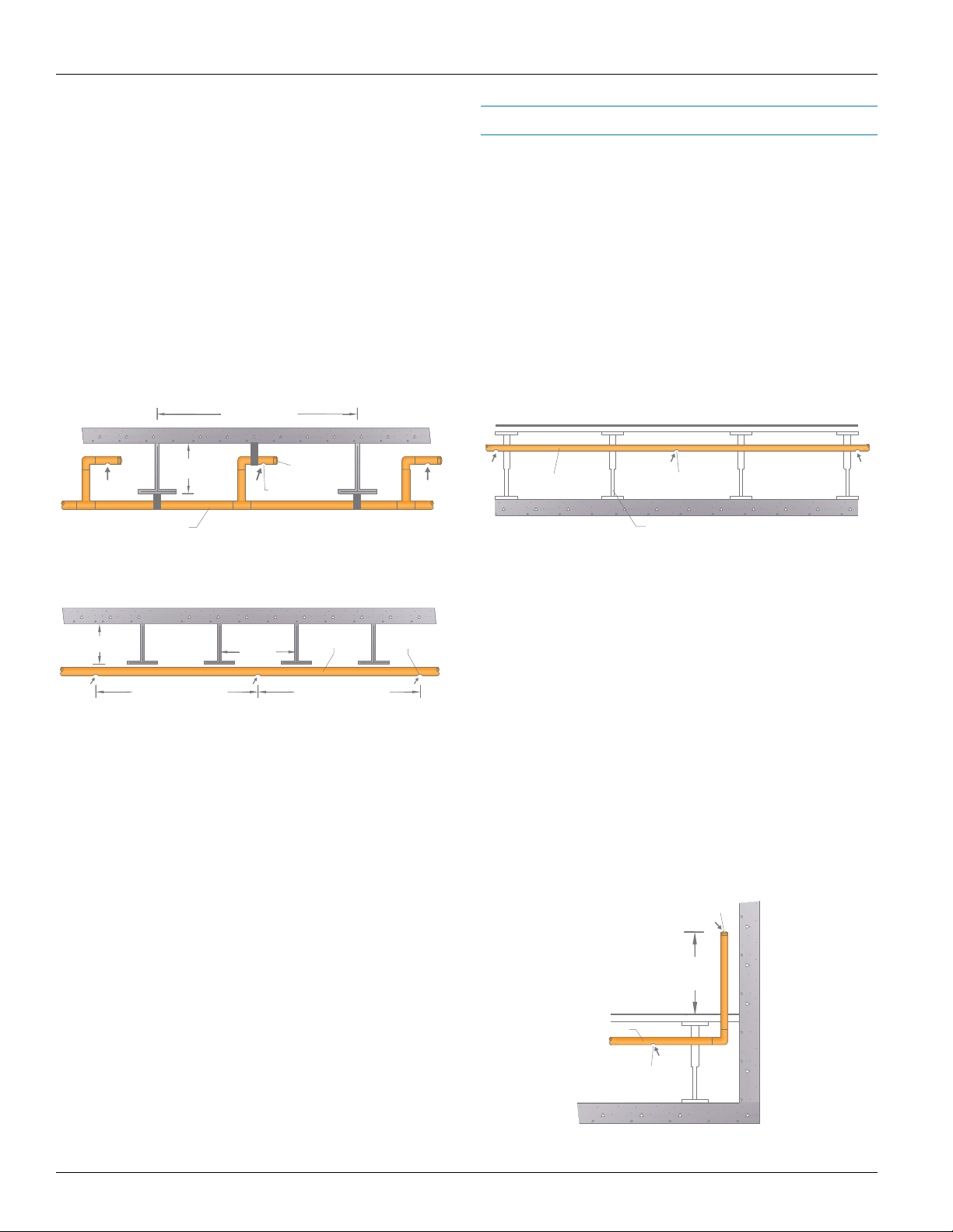
Ceiling Sampling
In typical ceiling installations, the pipe network is suspended
from 1" to 1 ft. (25 mm to 300 mm) below the ceiling level in the
protected area unless otherwise specified by local codes and
standards. This type of installation is the most common. It could
be used in offices, warehouses, equipment rooms and a variety
of other types of installations. PipeIQ can also help provide
guidance for the design.
Frequently Asked Question – How do I design for
a peak ceiling?
When designing peak ceiling applications, the spacing
requirements of NFPA-72® apply. A sample port shall be
provided within 36" from the center of the peak on both sides.
The next sample port from the center shall comply within the
design parameters of VEWFD, EWFD or SFD. If stratification
could potentially occur, it is recommended to also provide
sample ports along the wall.
Adjacent sample port shall
be located based on spacing
requirements. (VEWFD, EWFD, SFD)
Sampling Ports
3 ft.
Figure 12: Ceiling sampling.
Air sampling pipe located 3 ft.
from the center of the peak
on both sides.
Sampling pipe
network -Typ.
Sample port -Typ.
Figure 13: Peak ceiling sampling design.
FAAST Detector
12
Page 13
User Guide: Aspirating Smoke Detector Pipe Installation
Sampling Pipe
Floor
Ground
Floor Supports
Floor VoidSampling Port
Under Floor Protection
Inter-Beam / Below-Beam Sampling
When large ceiling beams are used in construction, pockets of
space are created between the beams. In normal circumstances, the pipe network is mounted on the bottom of the beams
and does not sample the large space between the beams. If it
is necessary to cover this space, a rigid pipe in the shape of an
inverted “L” can be extended vertically from the pipe network
up into the area between the beams so that the pipe reaches up
towards the ceiling in these locations. The sampling port should
be drilled just before the end cap on the horizontal portion of the
pipe. The ends of these sampling pipes should be capped with
an end cap, which may or may not have a sample port based
on the pipe network design.
Beam Pocket
+40% (0.4H)
N/A
End cap
Sampling Port
Sampling Pipe Sampling Port
+10% (0.1H)
Sampling Pipe
Figure 14: Inter-beam sampling.
-10% (0.1H)
MAX SPACING MAX SPACING
Figure 15: Below-beam sampling.
Floor Void Sampling
The FAAST system is well suited to protect concealed voids,
either in the ceiling or under the floor. Some locations use either
ceiling and/or under floor voids as return air plenums (ducts).
A pipe network must be designed to monitor the flow of return
air through these areas. Some ceiling and floor voids are used
for cable runs or for small equipment installation. Monitoring of
these areas must be done using a pipe network designed for
operation in these areas. When installing pipe in a floor void,
keep in mind that the air sampling ports are still located at
the bottom of the pipe. This means the pipe would be located
towards the upper portion of the void.
Figure 16: Floor void sampling.
Frequently Asked Question – Can I monitor the ceiling and
under the oor with one detector?
FAAST can monitor two areas with one detector, however,
it is not recommended practice due to pressure differentials.
Areas with pressure difference of +/- 20% delta of one another
can create air flow faults. Therefore it is recommended to
provide each area with its own detector.
Floor Void Test Sample Port
Frequently Asked Question – How do I know if the beam
pocket has to be protected?
In exposed beam construction the sample port shall be spaced
based on the requirements of NFPA 72®. If the beam depth is
equal to or greater than 10% of the ceiling height and beam
spacing is greater than or equal to 40% of the ceiling height,
than detection shall be provided in each beam pocket per NFPA
72®. For beams with less than 10% of ceiling height, smooth
ceiling spacing shall be permitted.
It is recommended to install a test sample port when designing
an under floor system. A test sample port will allow an easier
commissioning process without disrupting the floor operation.
It is recommended to locate the test port at the end of each
branch pipe at a minimum of 18 in. above the raised floor. The
port diameter should be determined and verified by using the
PipeIQ Software.
Sampling Pipe
Sampling Port
Figure 17: Floor void test sample port location.
13
Floor
End cap with
Sample Test Port
18 in.
(450 mm)
Page 14

Object Protection
User Guide: Aspirating Smoke Detector Pipe Installation
Cabinet Sampling
Equipment cabinet sampling may be accomplished in two
ways: pipe networks and sampling ports can be installed directly inside the equipment cabinet, or directly over the
equipment cabinets being monitored if the cabinets have
ventilation grills.
In-Cabinet Sampling
For in-cabinet sampling, capillary tubes can be used to enter
the equipment cabinet. The capillary tube is connected to the
pipe network via a tee connection with an adapter. The
maximum length of these capillary tubes is 26 ft. (8 m).
PipeIQ can help create an appropriate design.
An alternate to capillary tubes is a rigid drop tube. In this
application, the pipe network is run over a row of cabinets and
drop tubes are run down to each cabinet. This tube or pipe
should be less than or equal to the network pipe diameter and
is connected to the top of the cabinet and to the pipe network
via a tee connection. The pipe could also come up from under
a floor void in to a cabinet.
Cabinets with extractor fans may cause sampling problems
when the sample port is on the top of the cabinet. The
extractor fan creates a low pressure area within the cabinet that
can stop air from being drawn into the detector system at the
sampling port. This type of installation must be checked carefully for proper sampling operation. This can be accomplished
using canned smoke at the sample port location.
Above-Cabinet Sampling
In above-cabinet sampling, the pipe network should be installed
directly over the cabinets that will be protected. Sampling ports
are placed over the cabinet ventilation grills. Ports should be
oriented so that they face into the air stream coming from the
cabinet. If there is more than one exhaust from a cabinet, a
sampling port should be installed over each opening.
NOTE: With either application, it is best to locate the sampling
port in the path of the air flow near the top of the cabinet.
Top View of Cabinet
Figure 18: In-cabinet sampling.
Figure 19: Above-cabinet sampling.
14
Page 15

User Guide: Aspirating Smoke Detector Pipe Installation
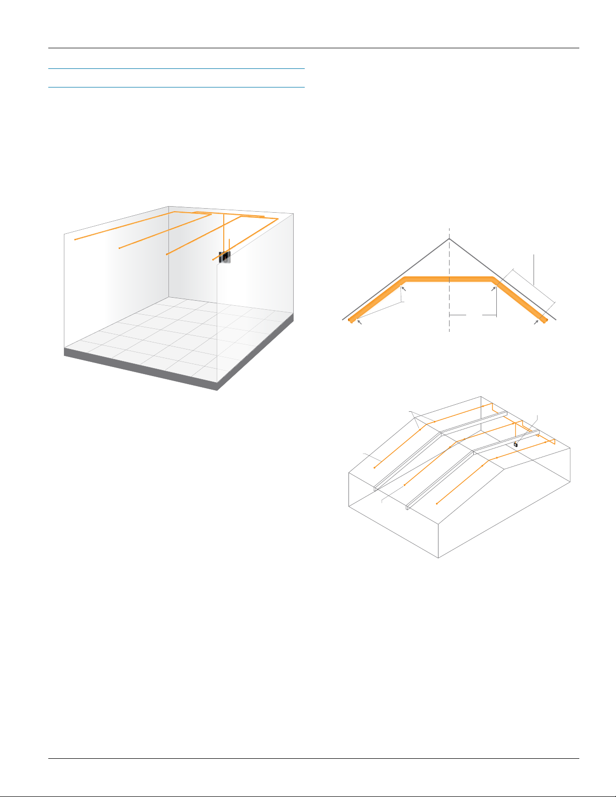
Large Area Protection
Large volume areas and areas with high ceilings require
special design considerations for the pipe network design.
Stratification occurs when smoke is heated by smoldering
or burning materials and becomes less dense than the
surrounding cooler air. The smoke rises until there is no longer
a difference in temperature between the smoke and the surrounding air (see NFPA 72-2013 A.5.7.1.10). Stratification,
therefore, may occur in areas where air temperature may be
elevated at the ceiling level, especially where there is a lack of
ventilation. When stratification is likely to occur, conventional
pipe network sampling may not be effective.
One method to overcome smoke stratification is to create
vertical sampling pipes in addition to the horizontal pipe
network on the ceiling. The vertical sampling pipe should
have sampling ports at various heights to sample within any
stratification layers present in the area, as shown in figure 20.
Air sampling ports on
air sampling network -Typ.
Cold Area Protection
The FAAST detector is approved for operating temperatures
ranging from 32°F (0°C) to 100°F (38°C) and sampled air
temperature form -4°F (-28°C) to 140°F (60°C). However,
special considerations should be taken when operating at the
extreme end of these ranges.
The temperature in a cold area is typically at or just above
freezing. In designing a pipe system, the pipes should be kept
out of the immediate airflow from a chiller unit, if used, as its air
is often significantly colder than the room itself. Sample ports
should also be located away from frequently used doors
where possible.
Often, the temperature of the cold room is outside the operating
temperature of FAAST and the device must be mounted outside
of the room with the pipe network being run in to the protected
space. Depending on the temperature of the air being removed
from the room, heating elements may be required, and a
condensation trap installed to catch any condensation or
moisture that may enter the device.
For more information on deploying FAAST in cold storage
applications, see the cold storage white paper at
systemsensor.com/faast.
Air sampling test port
located at the end of
each branch pipe -Typ.
Stratification Layer
of Smoke
FAAST Detector
Air sampling ports on
vertical pipe to capture
smoke stratification -Typ.
Figure 20: Large area protection.
Frequently Asked Question – Does FAAST eliminate
stratication issues?
No, stratification occurs when smoke cools to a temperature
equal to the surrounding air. To overcome the effects of
stratification, provide sample ports on the pipe as it runs
vertically up the wall. It is recommended to provide sample
ports for stratification when the ceiling height exceeds 30 ft.
or when ceiling elevations transition, creating a jet stream.
Exhaust pipe back to
area being monitored
FAAST Detector shall be
mounted 5 ft.- 0 in. AFF.
Piping shall be pitched
accordingly based on
the natural flexibility the
pipe will allow.
Maintain a
minimum of 16 in.
of vertical pipe.
From air sampling network,
run additional horizontal piping
after exiting cold area. Sample
air temperature must be above
-4°F (-20°C) before entering
the detector.
Install drip loop on tee
fitting prior to entering
detector.
To nearest drain or
condensate collector.
Always maintain water
halfway of drip loop.
Figure 21: Cold area protection.
15
Page 16

High Air Exchange Areas
User Guide: Aspirating Smoke Detector Pipe Installation
Typically, high air exchange areas have some form of
mechanical ventilation to maintain constant or cyclical air
flow for heating, cooling or maintaining some other sort of
special environment. Smoke tends to travel with the air flow, so
positioning sampling pipes near the return of an air handling
unit or heating/air conditioning unit ensures early detection of
particulate in the area.
Normal sampling methods for high air exchange areas are a
combination of return air and ceiling sampling. The return air
sampling provides protection when the air flow is present. The
ceiling network provides protection when the air flow is off.
Local codes typically require smaller sample areas (closer
spacing of sample ports) as the air flow rate increases.
Return Air Sampling
Return air sampling provides an effective means of Very Early
Warning in a high air velocity environment. Placing the pipe
network sampling ports directly in the air stream at a return
air grill allows the system to monitor air that has circulated
throughout the protected area.
The following guidelines should be reviewed and followed to
ensure proper sampling by the detector system:
1. More than one sampling location may be required for large
air grills. NFPA 76 recommendations specify that each
sampling port can cover a maximum of 4 sq. ft. (0.4 m2)
2. Sampling ports should be aligned at an angle of 20 to 45
degrees to the direction of the maximum air flow.
3. Sampling pipes should be placed in the path of the
greatest air flow.
4. The number of bends in the pipe network should be kept
to a minimum.
5. Pipe ends should be capped with an end cap. Depending
on the pipe design and PipeIQ recommendations, the end
caps may or may not have a sampling port.
6. Socket unions should be used in locations where the pipe
network requires the removal of the pipes on a regular
basis for maintenance purposes.
7. Use of standoff fittings to keep the pipe network at least 2"
to 8" (50 mm to 200 mm) in front of the grill for high velocity
air flow locations. Installing the network any closer to the
input grill locates the sample port in an area of negative air
pressure.
8. Always keep in mind that the monitored environment
should still ensure coverage even if the manufactured air
flow gets disrupted.
Generally the FAAST detector should not monitor more than
two air handling units. When monitoring multiple units with one
device, the AHUs should have similar flow at all times. The
number of air handlers monitored is limited by the maximum
length of the pipe network. However, the degree of particle
dilution and air movement that occurs with multiple air handlers
can adversely affect system response times. Final system
testing should be done to confirm actual response times.
End cap
4ft. x 4ft.
Intake
Sample Ports
• NFPA calls for 4 sq. ft. max
per sample port
• Pipes to be positioned on 2-8"
stand-offs from grill opening
• Ports to be positioned 20" - 45"
into the direction of air ow
Figure 22: Return air sampling.
16
Page 17

In-Duct Sampling
User Guide: Aspirating Smoke Detector Pipe Installation
The FAAST detector is approved for in duct applications.
National and local safety standards and codes recognize the
ability of air duct systems to transfer smoke, toxic gases, and
flame from area to area. Sometimes smoke can be of such
quantity as to be a serious hazard to life safety unless blowers
are shut down and dampers are actuated. The primary purpose
of duct smoke detection is to prevent injury, panic, and property
damage by reducing the spread (recirculation) of smoke.
Duct smoke detection also can serve to protect the air
conditioning system from fire and smoke damage, and can
be used to assist in equipment protection applications, for
example, in the ventilation/exhaust duct work of mainframe
computers and tape drives. For additional information relating
to duct applications, refer to the duct application white paper
at systemsensor.com/faast.
Design Considerations for In-Duct Sampling
The following guidelines are necessary to obtain the best
installation results.
1. Pipes should always be supported at both duct walls –
rubber grommets can be used. Silicon sealer must also
be used to ensure an airtight seal in the duct walls.
2. Inlet pipes must be inserted between six and ten
duct widths or diameters (for round ducts) from any
disturbances to the flow generated by sharp bends,
plenums, nozzles, branch connections, etc…
3. Sampling ports should be located no closer than 2” to
the duct wall.
4. Ports on the inlet pipe should face 20-45 degrees into the
air flow with the ports concentrated at the center of the
duct as shown in figure 22.
5. The exhaust pipe must have 4, 3/8" (9.5 mm) ports. Ports
should be concentrated in the middle of the duct’s width
and spaced evenly. Ports on the exhaust pipe should be
oriented such that they face away from the air flow.
Small Duct Sampling
For ducts with a width less than 3 ft. (1 m), the inlet pipe should
be installed at the midpoint of the duct height or diameter.
Exhaust pipes should be inserted at 18" (0.5 m) downstream
from the input pipe. The exhaust pipe should be at one quarter
of the duct height or diameter, as shown in figure 23. To avoid
dilution, sampling pipes should be located before fresh air
intakes and before the exhaust air output.
Small Diameter Duct
Air Flow
Inlet Pipe
Figure 24: Small duct sampling.
Duct Width
12 in.
(300 mm)
20 in.
(500 mm)
28 in.
(700 mm)
36 in.
(900 mm)
Table 4: Port sizes for small ducts.
Number
of Ports
2
3
4
5
H/2
Port Size
1/4 in.
(6.5 mm)
1/4 in.
(6.5 mm)
11/64 in.
(4.5 mm)
5/32 in.
(4 mm)
Outlet Pipe
H/4
Nominal Pipe
Flow Rate (CFM)
1.84 cfm
(52.0 L/min)
1.83 cfm
(51.9 L/min)
1.70 cfm
(48.1 L/min)
1.81 cfm
(51.2 L/min)
H
Direction of
Air Flow
Exhaust Pipe from
FAAST Device
Figure 23: Design considerations for in-duct sampling.
Air Supply to
FAAST Device
17
Page 18

User Guide: Aspirating Smoke Detector Pipe Installation
Large Duct Sampling
For ducts with a width of 3 ft. to 7 ft. (1 m to 2 m), two branch
pipes are recommended for the inlets. Inlet pipes should enter
a quarter of the way from the top and bottom of the duct, as
shown in figure 24.
The exhaust pipe should be inserted approximately 18" (0.5 m)
from the inlet pipes and half way up the height of the duct.
To avoid dilution, sampling pipes should be located before
fresh air intakes and before exhaust air output.
Large Diameter Duct
Inlet Pipe
Air Flow
Figure 25: Large duct sampling.
Duct Width
3 ft. 4 in.
(1 m)
5 ft.
(1.5 m)
6 ft. 6 in.
(2 m)
Table 5: Port sizes for large ducts.
The information in table 4, on page 17, and table 5, above,
applies to a 15 ft. (4.6 m) inlet pipe and a 10 ft. (3 m) exhaust
pipe. Always check local codes and standards for port size
and spacing.
Number
of Ports
6
8
10
3H/4
Inlet Pipe
Port Size
9/64 in.
(3.5 mm)
1/8 in.
(3 mm)
1/8 in.
(3 mm)
Outlet Pipe
H/2
H/4
Nominal Pipe
Flow Rate (CFM)
1.77 cfm
(50.2 L/min)
1.80 cfm
(50.9 L/min)
2.10 cfm
(59.6 L/min)
Port Orientation
Sampling response time can also be improved by avoiding high
and low velocity air flows. Ports on the inlet pipes should be
facing 20-45 degrees from the airflow. The angle of the ports
can be adjusted for complete flow independence from the AHU
by following some simple steps outlined in the Duct Application
white paper on the FAAST website. Ports on the exhaust pipe
should be facing away from the airflow.
For additional information relating to duct applications, refer to
the duct application white paper at systemsensor.com/faast.
C
B
A
20° - 45°
from direction
of Air Flow
A. Airow Streamlines
B. Low velocity (high static pressure) area
C. High velocity (low static pressure) area
Figure 26: Port orientation.
Monitoring Voids
In these high air exchange environments, detection systems
should be installed in any void, unless the void is completely
empty and presents no fire risk. If the void contains cabling
and/or equipment that can initiate or contribute to a fire,
monitoring for combustion is highly recommended. The
sampling port spacing for these areas is the same as the
requirement for the rest of the area, in accordance with the
relevant local codes and standards.
When sampling pipes are installed in shallow voids having poor
ventilation, special care should be taken to position the piping
as close to the top of the void as possible. This gives the best
early warning due to the likelihood of the initial smoke layer
taking up only the top 10% of the void height.
18
Page 19

User Guide: Aspirating Smoke Detector Pipe Installation
Basic Pipe Network Cleaning
and Maintenance Procedure
Periodic maintenance of the FAAST Fire Alarm Aspiration Sensing Technology pipe network is recommended in environments
with high amounts of airborne particulate, or cold environments
where condensation may freeze on the sampling port and affect
pipe network performance. Annual maintenance of the pipe
network is recommended for all installations.
Low flow faults on devices which have been installed and operating normally for a period of time may signal the need for pipe
network cleaning.
Pipe Network Maintenance
During installation of the pipe network, it is recommended that
a valved tee fitting be installed 6 inches to 1 foot from the pipe
inlet so that the pipe entering the detector is not subject to any
flow of air during the pipe network maintenance. Forcing air in
to, or out of, the FAAST unit by any means other than the inherent fan may cause damage to the device and nullify the device
warranty.
Prior to beginning pipe network maintenance:
• Place the device in isolate or disable mode, or power
down.
• Remove the pipe network from the device, or switch the
valve on a valved tee fitting to ensure that no air can be
force in to or out of the device
• If the low flow condition persists, perform another manual
check of the pipe network against the pipe layout report
generated by PipeIQ. Also, if the exhaust pipe is not
situated in the protected space the low/high flow condition
could be the result of differences in room pressures that
have changed do to open doors, windows or upgrades to
ventilation units.
Filter Maintenance
Filter maintenance is required only when a ‘Filter’ fault is indicated by the FAAST unit. Perform the following procedure to
replace the filter assembly:
1. Remove power from the system.
2. Open the door on the right side of the device that covers
the LED system indicators.
3. Remove the plastic name card over the LEDs.
4. Remove the two screws holding the filter assembly into
the device.
5. Remove the filter assembly and replace it with a
new assembly.
6. Torque the two Phillips-head screws to 6in-lb (0.7 N-M)
or ¼ turn past “lightly snug’. DO NOT OVERTIGHTEN.
7. Replace the plastic name card over the LEDs.
8. Close the door and restore power to the system.
To perform pipe network maintenance:
• Affix a vacuum cleaner, or air compressor, to the end of
the pipe network or the entry in to the valved tee fitting.
• While the vacuum is running, use a dry brush or pipe
cleaner to swab out each sampling port in the pipe network. Leave vacuum running for 2 min following last port
cleaning.
Post pipe network maintenance:
• Reconnect pipe network to the FAAST device or switch
the valved tee tap
• Remove the device from isolate or disable mode, or
reapply power to the FAAST
• Observe the air flow pendulum on the user interface. The
two green indicators should be near center underneath
the device’s power indicator. If a low condition existed
before maintenance, this condition should be clear after
maintenance (NOTE: if the device is set to latch in fault,
the device will need to be reset to clear the fault)
19
Page 20

User Guide: Aspirating Smoke Detector Pipe Installation
Technical Support
System Sensor strives to provide our customers with outstanding support for the FAAST Fire Alarm Aspiration Sensing Technology
and all of our products. For more information, contact us using one of the methods below:
Web: E-mail: Phone:
systemsensor.com/faast systemsensor.com/contact 800.736.7672 (press 2) Mon-Fri, 7:30 a.m. – 5:00 p.m. CST
User Guide: Aspirating Smoke Detector Pipe Installation
©2014 System Sensor. ASUG32301 • 02/14
 Loading...