

Page 1

PDRP-1002
3825 Ohio Avenue
St. Charles, IL 60174
1-800-SENSOR2
Fax: (630) 377-6495
Series
Agent Release Control
System
Instruction Manual
Document 51135
I56-1358-01
04/06/2001 Rev:
PN 51135:B0 ECN 00-543
B
Page 2

Fire Alarm System Limitations
While a fire alarm system may lower insurance
rates, it is not a substitute for fire insurance!
An automatic fire alarm system–typically made up of smoke
detectors, heat detectors, manual pull stations, audible warning devices, and a fire alarm control with remote notification
capability–can provide early warning of a developing fire.
Such a system, however, does not assure protection against
property damage or loss of life resulting from a fire.
The Manufacturer recommends that smoke and/or heat detectors be located throughout a protected premise following the
recommendations of the current edition of the National Fire
Protection Association Standard 72 (NFPA 72),
manufacturer's recommendations, State and local codes, and
the recommendations contained in the Guide for Proper Use
of System Smoke Detectors, which is made available at no
charge to all installing dealers. A study by the Federal Emergency Management Agency (an agency of the United States
government) indicated that smoke detectors may not go off in
as many as 35% of all fires. While fire alarm systems are designed to provide early warning against fire, they do not guarantee warning or protection against fire. A fire alarm system
may not provide timely or adequate warning, or simply may not
function, for a variety of reasons:
Smoke detectors may not sense fire where smoke cannot
reach the detectors such as in chimneys, in or behind walls, on
roofs, or on the other side of closed doors. Smoke detectors
also may not sense a fire on another level or floor of a building. A second-floor detector, for example, may not sense a
first-floor or basement fire.
Particles of combustion or "smoke" from a developing fire
may not reach the sensing chambers of smoke detectors because:
• Barriers such as closed or partially closed doors, walls, or
chimneys may inhibit particle or smoke flow.
• Smoke particles may become "cold," stratify, and not reach
the ceiling or upper walls where detectors are located.
• Smoke particles may be blown away from detectors by air
outlets.
• Smoke detectors may be drawn into air returns before
reaching the detector.
The amount of "smoke" present may be insufficient to alarm
smoke detectors. Smoke detectors are designed to alarm at
various levels of smoke density. If such density levels are not
created by a developing fire at the location of detectors, the
detectors will not go into alarm.
Smoke detectors, even when working properly, have sensing
limitations. Detectors that have photoelectronic sensing
chambers tend to detect smoldering fires better than flaming
fires, which have little visible smoke. Detectors that have ionizing-type sensing chambers tend to detect fast-flaming fires
better than smoldering fires. Because fires develop in different ways and are often unpredictable in their growth, neither
type of detector is necessarily best and a given type of detector may not provide adequate warning of a fire.
Smoke detectors cannot be expected to provide adequate
warning of fires caused by arson, children playing with
matches (especially in bedrooms), smoking in bed, and violent
explosions (caused by escaping gas, improper storage of
flammable materials, etc.).
Heat detectors do not sense particles of combustion and
alarm only when heat on their sensors increases at a predetermined rate or reaches a predetermined level. Rate-of-rise
heat detectors may be subject to reduced sensitivity over time.
For this reason, the rate-of-rise feature of each detector
should be tested at least once per year by a qualified fire protection specialist.
Heat detectors are designed to protect
property, not life.
IMPORTANT!
Smoke detectors must be installed in the
same room as the control panel and in rooms used by the system for the connection of alarm transmission wiring, communications, signaling, and/or power.
cated, a developing fire may damage the alarm system, crippling its ability to report a fire.
Audible warning devices such as bells may not alert people
if these devices are located on the other side of closed or
partly open doors or are located on another floor of a building.
Any warning device may fail to alert people with a disability or
those who have recently consumed drugs, alcohol or medication. Please note that:
• Strobes can, under certain circumstances, cause seizures
in people with conditions such as epilepsy.
• Studies have shown that certain people, even when they
hear a fire alarm signal, do not respond or comprehend the
meaning of the signal. It is the property owner's responsibility to conduct fire drills and other training exercise to make
people aware of fire alarm signals and instruct them on the
proper reaction to alarm signals.
• In rare instances, the sounding of a warning device can
cause temporary or permanent hearing loss.
A fire alarm system will not operate without any electrical
power. If AC power fails, the system will operate from standby
batteries only for a specified time and only if the batteries
have been properly maintained and replaced regularly.
Equipment used in the system may not be technically compatible with the control. It is essential to use only equipment
listed for service with your control panel.
Telephone lines needed to transmit alarm signals from a
premise to a central monitoring station may be out of service
or temporarily disabled. For added protection against telephone line failure, backup radio transmission systems are recommended.
The most common cause of fire alarm malfunction is inadequate maintenance. To keep the entire fire alarm system in
excellent working order, ongoing maintenance is required per
the manufacturer's recommendations, and UL and NFPA standards. At a minimum, the requirements of Chapter 7 of NFPA
72 shall be followed. Environments with large amounts of
dust, dirt or high air velocity require more frequent maintenance. A maintenance agreement should be arranged
through the local manufacturer's representative. Maintenance
should be scheduled monthly or as required by National and/
or local fire codes and should be performed by authorized professional fire alarm installers only. Adequate written records
of all inspections should be kept.
If detectors are not so lo-
LimWarLg.p65 01/10/2000
Page 3

Installation Precautions
Adherence to the following will aid in problem-free
installation with long-term reliability:
WARNING -
nected to the fire alarm control panel.
of power before servicing. Control unit and associated equipment may be damaged by removing and/or inserting cards,
modules, or interconnecting cables while the unit is energized.
Do not attempt to install, service, or operate this unit until this
manual is read and understood.
CAUTION -
Changes.
must be tested in accordance with NFPA 72 Chapter 7 after
any programming operation or change in site-specific software. Reacceptance testing is required after any change, addition or deletion of system components, or after any modification, repair or adjustment to system hardware or wiring.
All components, circuits, system operations, or software functions known to be affected by a change must be 100% tested.
In addition, to ensure that other operations are not inadvertently affected, at least 10% of initiating devices that are not
directly affected by the change, up to a maximum of 50 devices, must also be tested and proper system operation verified.
This system meets NFPA requirements for operation at
0-49° C/32-120° F
condensing) at 30° C/86° F. However, the useful life of the
system's standby batteries and the electronic components
may be adversely affected by extreme temperature ranges
and humidity. Therefore, it is recommended that this system
and all peripherals be installed in an environment with a nominal room temperature of 15-27° C/60-80° F.
Verify that wire sizes are adequate for all initiating and
indicating device loops. Most devices cannot tolerate more
than a 10% I.R. drop from the specified device voltage.
Several different sources of power can be con-
Disconnect all sources
System Reacceptance Test after Software
To ensure proper system operation, this product
and at a relative humidity of 85% RH (non-
Like all solid state electronic devices, this system may
operate erratically or can be damaged when subjected to lightning-induced transients. Although no system is completely
immune from lightning transients and interferences, proper
grounding will reduce susceptibility.
Overhead or outside
aerial wiring is not recommended, due to an increased susceptibility to nearby lightning strikes.
cal Services Department if any problems are anticipated or
encountered.
Disconnect AC power and batteries prior to removing or inserting circuit boards. Failure to do so can damage circuits.
Remove all electronic assemblies prior to any drilling, filing,
reaming, or punching of the enclosure. When possible, make
all cable entries from the sides or rear. Before making modifications, verify that they will not interfere with battery, transformer, and printed circuit board location.
Do not tighten screw terminals more than 9 in-lbs.
Over-tightening may damage threads, resulting in reduced
terminal contact pressure and difficulty with screw terminal
removal.
Though designed to last many years, system components
can fail at any time. This system contains static-sensitive
components. Always ground yourself with a proper wrist strap
before handling any circuits so that static charges are removed from the body. Use static-suppressive packaging
to protect electronic assemblies removed from the unit.
Follow the instructions in the installation, operating, and
programming manuals. These instructions must be followed
to avoid damage to the control panel and associated
equipment. FACP operation and reliability depend upon
proper installation by authorized personnel.
Consult with the Techni-
FCC Warning
WARNING: This equipment generates, uses, and can
radiate radio frequency energy and if not installed and
used in accordance with the instruction manual, may
cause interference to radio communications. It has
been tested and found to comply with the limits for class
A computing device pursuant to Subpart B of Part 15 of
FCC Rules, which is designed to provide reasonable
protection against such interference when operated in a
commercial environment. Operation of this equipment in
a residential area is likely to cause interference, in which
case the user will be required to correct the interference
at his own expense.
Canadian Requirements
This digital apparatus does not exceed the Class A
limits for radiation noise emissions from digital
apparatus set out in the Radio Interference Regulations
of the Canadian Department of Communications.
Le present appareil numerique n'emet pas de bruits
radioelectriques depassant les limites applicables aux
appareils numeriques de la classe A prescrites dans le
Reglement sur le brouillage radioelectrique edicte par le
ministere des Communications du Canada.
LimWarLg.p65 01/10/2000
Page 4
NFPA Standards
This control panel complies with the following NFPA standards:
• NFPA 2001 - Clean Agent Fire Extinguishing Systems
• NFPA 17 - Dry Chemical Extinguishing Systems
• NFPA 17A - Wet Chemical Extinguishing Systems
•NFPA 12 - CO2 Extinguishing Systems (High Pressure Only)
• NFPA 12A - Halon 1301 Extinguishing Systems
•NFPA 12B - Halon 1211 Extinguishing Systems
• NFPA 72 - Central Station Signaling Systems (Automatic, Manual, and Waterflow) - Protected
Premises Unit
Requires NOTI-FIRE 911AC DACT or 411UDAC Universal Digital Alarm Communicator
• NFPA 72 - Local Fire Alarm Systems (Automatic, Manual, Waterflow and Sprinkler Supervisory)
• NFPA 72 - Auxiliary Fire Alarm Systems (Automatic, Manual, and Waterflow)
Requires 4XTMF
• NFPA 72 - Remote Station Fire Alarm Systems (Automatic, Manual, and Waterflow)
Requires 4XTMF or NOTI•FIRE 911AC DACT or 411UDAC
Note: Applications which require the NOTI-FIRE 911AC are not FM approved.
Before proceeding, the installer should be familiar with the following documents.
NFPA Standards
NFPA Standards
• The above listed documentation
• NFPA 72 - Automatic Fire Detectors
• NFPA 72 - Installation, Maintenance, and Use of Notification Appliances for Fire Alarm Systems
• NFPA 72 - Testing Procedures for Signaling Systems
Underwriters Laboratories Documents
• UL 38 - Manually Actuated Signaling Boxes
• UL 217 - Smoke Detectors, Single and Multiple Station
• UL 228 - Door Closers - Holders for Fire Alarm Systems
• UL 268 - Smoke Detectors for Fire Alarm Systems
• UL 268A - Smoke Detectors for Duct Applications
• UL 346 - Waterflow Indicators for Fire Protective Signaling Systems
• UL 464 - Audible Signaling Appliances
• UL 521 - Heat Detectors for Fire Protective Signaling Systems
• UL 864 - Standard for Control Units for Fire Alarm Systems
• UL 1481 - Power Supplies for Fire Protective Signaling Systems
• UL 1638 - Visual Signaling Appliances
• UL 1971 - Signaling Devices for the Hearing Impaired
• CAN/ULC-S524-M91 Standard for Installation of Fire Alarm Systems
• CAN/ULC-S527-M87 Standard for Control Units for Fire Alarm System
Other
• NEC Article 300 - Wiring Methods
• NEC Article 760 - Fire Protective Signaling Systems
• Applicable Local and State Building Codes
• Requirements of the Local Authority Having Jurisdiction
• ADA - Americans with Disabilities Act
4
PDRP-1002 Instruction Manual PN 51135:B0 04/06/01
Page 5

NFPA Standards.......................................................................................................... 4
NFPA Standards .................................................................................................... 4
Underwriters Laboratories Documents ................................................................. 4
Other....................................................................................................................... 4
1. Product Description
Overview ...................................................................................................................... 7
Features .......................................................................................................................7
Options ........................................................................................................................7
Circuits ......................................................................................................................... 8
Input Circuits.......................................................................................................... 8
Output circuits........................................................................................................ 8
Front Panel Control Switches ................................................................................ 8
Suplemental Documentation ...................................................................................... 8
Control Panel............................................................................................................... 9
DIP Switch Functions................................................................................................ 10
Options ....................................................................................................................... 10
Transmitter Module - 4XTM .............................................................................. 10
Zone Relay Module - 4XZM .............................................................................. 10
Remote Annunciator - RZA-4X .......................................................................... 11
LED Interface Module - 4XLM .......................................................................... 11
Specifications ............................................................................................................. 12
AC Power............................................................................................................. 12
Battery (lead acid only)........................................................................................ 12
Initiating Device Circuits..................................................................................... 12
Notification Appliance and Releasing Circuits.................................................... 12
Alarm and Trouble Relays ................................................................................... 12
Resettable Power.................................................................................................. 12
Nonresettable Power ............................................................................................ 12
RMS Regulated Power......................................................................................... 12
2. Installation
Cabinet Mounting ..................................................................................................... 13
Removal of Circuit Board.................................................................................... 13
Mounting of Cabinet............................................................................................ 13
Attaching Conduit................................................................................................ 13
Reinstallation of Circuit Board ............................................................................ 14
Installing Optional Voltmeter/Ammeter................................................................. 15
Power Connections.................................................................................................... 16
AC Connections ................................................................................................... 16
Battery (DC) Connections.................................................................................... 16
Power-limited Wiring Requirements ...................................................................... 17
Initiating Device Circuits.......................................................................................... 18
Four-Wire Smoke Detector Connections............................................................. 19
Output Circuits.......................................................................................................... 20
Notification Appliance Circuits ........................................................................... 20
Releasing Circuits ................................................................................................ 21
Alarm Relay Circuit ............................................................................................. 22
Trouble Relay Circuit........................................................................................... 22
Powering External Devices....................................................................................... 22
Optional Modules ...................................................................................................... 23
Overview.............................................................................................................. 23
Installation - Upper Position ................................................................................ 23
Installation - Lower Position................................................................................ 24
Setup and Configuration ...................................................................................... 25
Transmitter Module - 4XTM ........................................................................ 25
Table of Contents
Table of Contents
PDRP-1002 Instruction Manual PN 51135:B0 04/06/01
5
Page 6

Table of Contents
Zone Relay Module - 4XZM ........................................................................ 26
LED Interface Module - 4XLM.................................................................... 27
Setting Mode of Operation ....................................................................................... 28
DIP Switch Functions........................................................................................... 28
Switch #1 - Cross Zone................................................................................. 28
Switch #2 - Supervisory/Releasing Service.................................................. 29
Switch #3 and #4 - Timer Delay................................................................... 29
Switch # 5 and #6 - Abort Function.............................................................. 29
Zone Relay Module Configuration ...................................................................... 30
Power-Up Procedure................................................................................................. 31
3. System Operation
System Status LEDs .................................................................................................. 33
Control Switches........................................................................................................ 34
Zone Status LEDs...................................................................................................... 34
Piezo............................................................................................................................ 35
Supervisory Service ................................................................................................... 35
Zone Disable............................................................................................................... 35
Last Event Recall....................................................................................................... 36
Non-Silenceable Service ............................................................................................ 36
Sprinkler Supervisory Tracking .............................................................................. 36
System Events ............................................................................................................ 36
Standby Condition................................................................................................ 36
System Trouble Condition ................................................................................... 36
Single Zone in Alarm (Cross Zone) Condition .................................................... 37
Both Zones in Alarm (Cross Zone) Condition..................................................... 37
Manual Discharge Station Alarm Condition........................................................ 37
Brownout Condition............................................................................................. 37
Appendix A: Secondary Power Calculations
Standby Battery Requirements................................................................................ 39
Calculating the Battery Capacity............................................................................. 40
Appendix B: Compatible Devices
Two-wire Smoke Detectors, UL Listed.................................................................... 41
Four-wire Smoke Detectors, UL Listed................................................................... 42
FM Approved Releasing Devices ............................................................................. 42
Notification Appliances, UL Listed.......................................................................... 43
Door Holders, UL Listed........................................................................................... 45
24 VDC Relays, UL Listed........................................................................................ 45
Appendix C: NFPA Standard-Specific Requirements
Minimum System Requirements.......................................................................... 47
Additional Requirements...................................................................................... 47
NFPA 72 - Signaling Systems for Central Station Service
(Protected Premises Unit)......................................................................... 47
NFPA 72 - Auxiliary Fire Alarm System ..................................................... 47
NFPA 72 - Remote Station Fire Alarm System............................................ 47
Digital Alarm Communicator/Transmitter - Noti-Fire 911AC............................. 48
Universal Digital Alarm Communicator - 411UDAC............................................ 49
Local Energy Municipal Box.................................................................................... 50
Remote Station Receiver - RS82-9 ........................................................................... 51
Appendix D: Testing & Maintenance
Testing ........................................................................................................................ 53
Inspection ............................................................................................................. 53
Alarm Test............................................................................................................ 53
Maintenance............................................................................................................... 53
Troubleshooting......................................................................................................... 53
6
PDRP-1002 Instruction Manual PN 51135:B0 04/06/01
Page 7

Overview
Features
1. Product Description
The PDRP-1002 Agent Release Control System has been designed as a control center for use in automatic
fire supression systems. The panel is a feature-packed control unit suitable to perform detection and control
functions associated with the release of gaseous agent/special hazard fire protection systems. The PDRP1002 is designed for maximum reliability with 100% solid state circuitry and isolated relay contacts for
outside interfacing and features programmable options to allow on-site customizatio n of the unit for various
operating configurations.
An integral standby battery system, with charger, is provided. In case of commercial AC power
interruption, automatic switchover to the battery system will provide power to the panel for a minimum
of 24 hours.
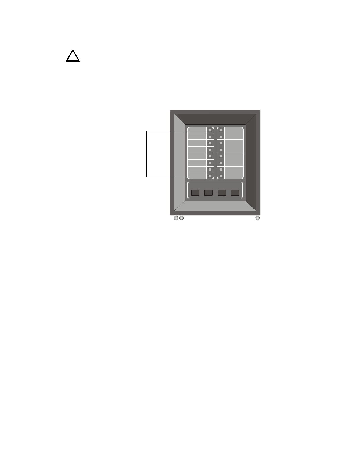
The FACP is supplied complete with backbox, hinged door, control switches, and indicator LEDs.
The entire unit is housed in a standard sheet-metal enclosure with 1/2 in. (12.7 mm) and 3/4 in. (19.05 mm)
conduit knockouts available.
The PDRP-1002 is a 110/120 VAC agent release control panel. The PDRP-1002E is a 220/240 VAC agent
release control panel.
• Microprocessor-controlled
• Power-limited on all circuits except Municipal Box
Output and Releasing Circuits
• Alarm and trouble resound
• Four Style B/D Initiating Device Circuits
• Two Style Y/Z Notification Appliance Circuits
• Two Style Y only Release Circuits
• General alarm and trouble relays
• Delay Timer (adjustable)
• Three abort function options
• Abort and manual release circuits
• Designed for supression standards
• Disable/enable controls per Initiating Device Circuit
• Last Event Recall
• Battery /Earth fault supervision
• Current protection on all notification circuits
• RMS regulated output power, 2.25 amps
• 7 amp-hour (AH) to 18 AH battery options, up to 90
hours standby
• Resettable and nonresettable regulated power
outputs
• Extensive transient protection
• Watchdog timer to supervise microprocessor
• Output circuits protected against false activations
• Slide-in zone identification labels
• Steel cabinet 14.5” (36.83cm) wide by 16.00”
(40.64cm) high by 4.75” (12.07cm) deep
Options
• 4XZM Module for 4 zone/function relays
• 4XTM Transmitter Module - Complies with NFPA
72 Auxiliary and Remote Station Protective
Signaling systems
• 4XMM Volt/Amp Meter Module
• RZA-4X Supervised remote annunciator (requires
4XLM Interface Module)
• 411UDAC or NOTI•FIRE 911AC Digital
Communicator - Complies with NFPA 72 Central
Station and Remote Station Protective Signaling
systems
Note: Applications which require the 411UDAC or the NOTI-FIRE 911AC are not FM approved.
PDRP-1002 Instruction Manual PN 51135:B0 04/06/01
• Cross-zone option
• Supervisory Input option
• Dead-front dress panel option (DP-4X) (Required
for Canadian applications)
• Trim ring for flush mount between 16 in. (40.64 cm)
center studs (TR-4XR)
7
Page 8

1. Product Description Circuits
Circuits
Input Circuits
Detector Zone 1 (Style B/D)
Detector Zone 2 (Style B/D)
Abort (Style B/D)
Manual Release (Style B/D)
Note: Optional auxiliary relay module 4XZM tracks these four circuits.
Output circuits
Notification Appliance Circuit 1 (Style Y/Z)
Notification Appliance Circuit 2 (Style Y/Z)
Releasing Circuit 1 (Style Y)
Releasing Circuit 2 (Style Y) / Supervisory Input (StyleB)
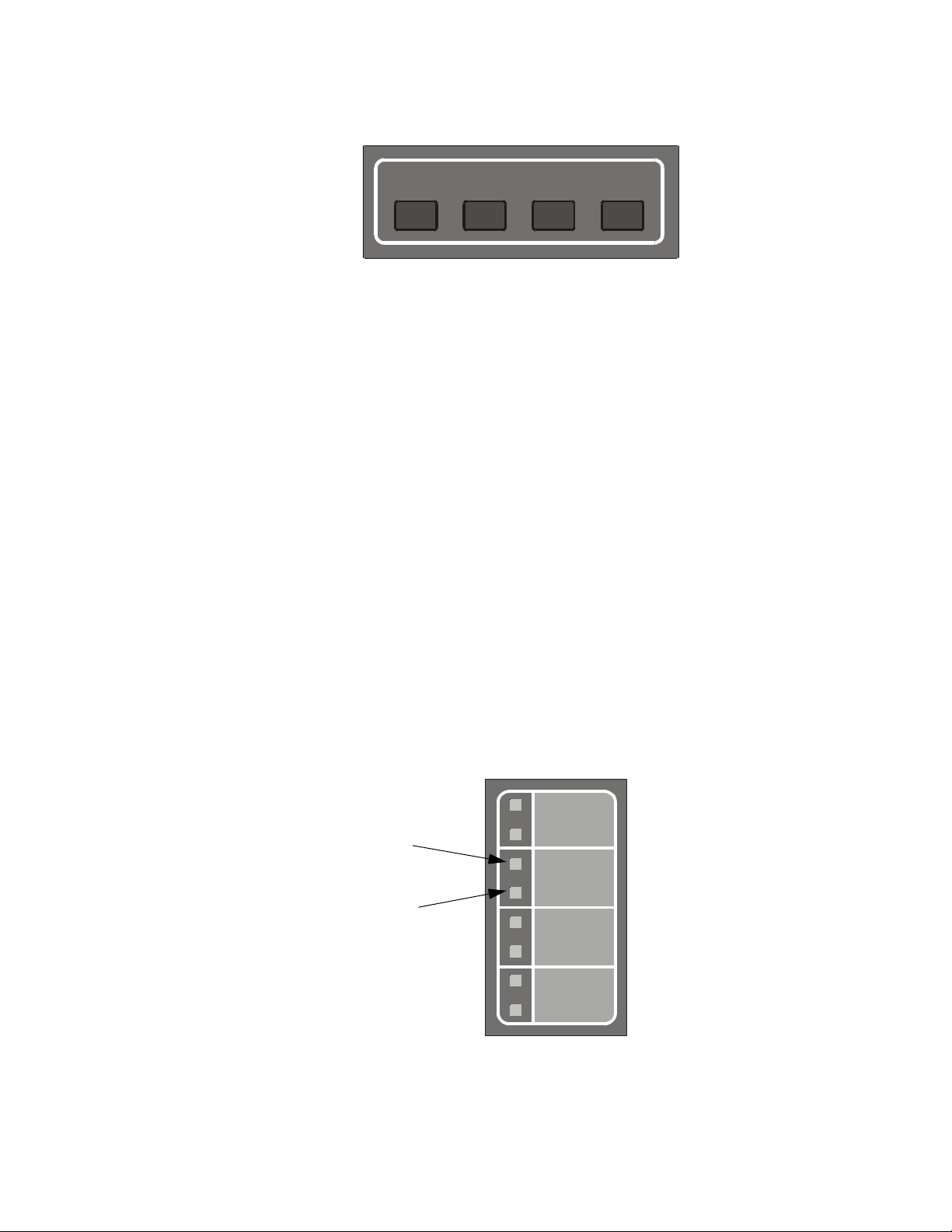
Front Panel Control Switches
Switch 1 - Tone Silence
Switch 2 - Alarm Silence
Switch 3 - Alarm Activate
Switch 4 - System Reset
Suplemental Documentation
The table below lists document sources containing additional information regarding the MS-4424:
For information on... Refer to... Part Number
Digital Alarm
Communicator/Transmitters
Remote Station Receiver Fire•Lite RS82-9 Instruction Manual 15400
Voltmeter/Ammeter 4X Series Power Meter PID 15396
NOTI-FIRE 911A & 911AC
Instruction Manual
411UDAC Instruction Manual
74-06200-005
51073
8
PDRP-1002 Instruction Manual PN 51135:B0 04/06/01
Page 9
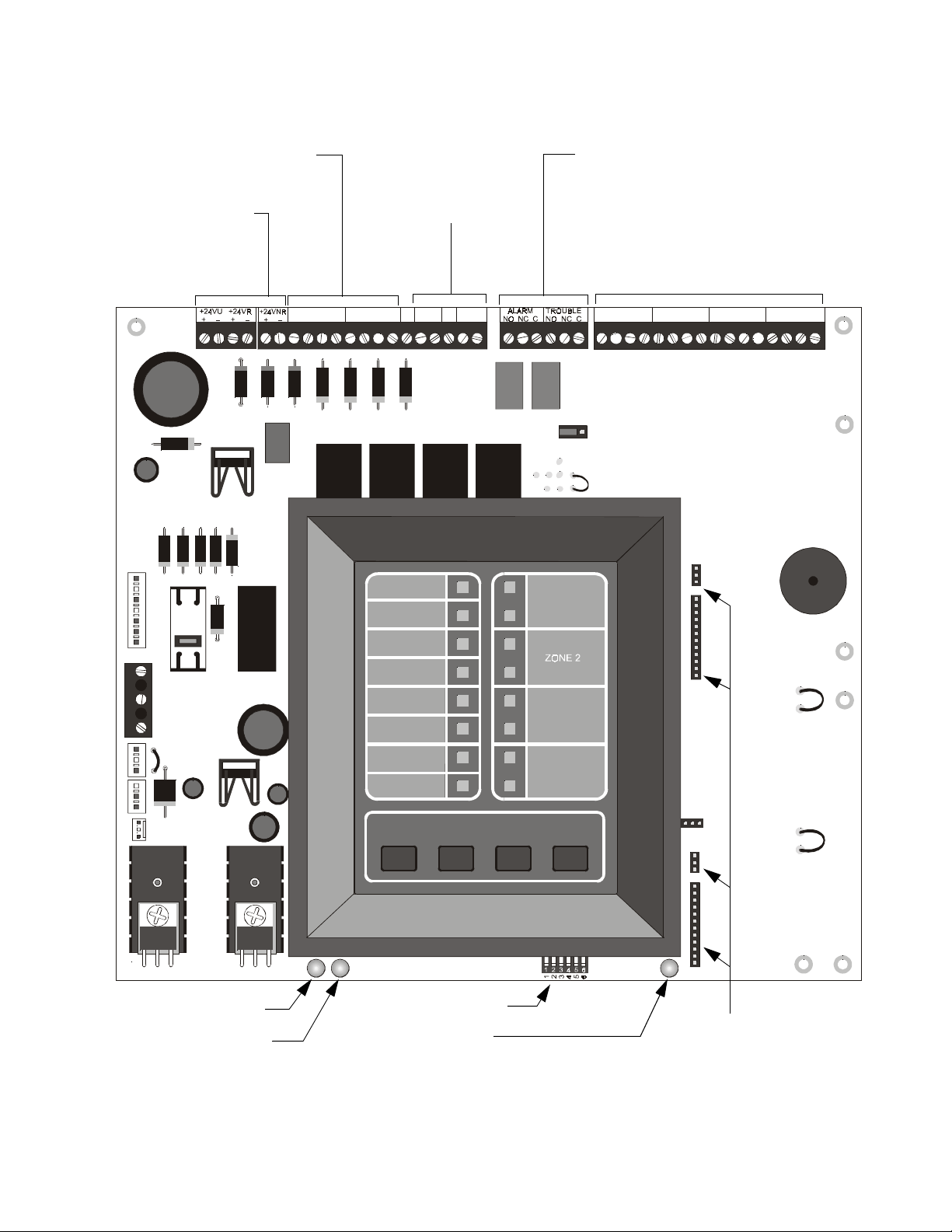
Control Panel 1. Product Description
Control Panel
Notification Appliance Circuits
Style Z (Class A) / Style Y (Class B)
24VDC
Regulated Nonresettable
Regulated Resettable
RMS-Regulated
B+ A+ A– B–
TB1
J1
OUT#1
OUT#2
B+ A+ A– B–
AC POW ER
SYSTEM
RELEASE
Releasing Circuits
Style Y (Class B)
OUT#4
OUT#3
B+ B–
B+ B–
TB2
ALARM
TB3
GEN
ALM1
GEN
ALM2
Relays
Alarm Contacts
Trouble Contacts
JP1
SUPV 1
SUPV 2
ZONE 1
#1 - Initiating Device Circuit
#2 - Initiating Device Circuit
#3 - Abort Switch
#4 - Manual Release
Style D (Class A) / Style B (Class B)
IN # 1
B+ A+ A– B–
IN # 2
B+ A+ A– B–
IN # 3
B+ A+ A– B–
J4
J5
IN # 4
B+ A+ A– B–
TB4
TB5
J2
AMP
J9
J3
Battery Fail LED
Ground Fault LED
SUPERVISORY
SYSTEM
TROUBLE
CIRCUIT
TROUBLE
ALARM
SILENCED
POWER
TROUBLE
TONE
SILENCE
SW1 - DIP Switch
Micro Fail LED
ABORT
MANUAL
RELEASE
ALARM
SILENCE
ALARM
ACTIVATE
SYSTEM
RESET
Figure 1 Control Panel
SW1
OPT1
J10
OPT2
J7
J8
MRP4424-board.cdr
J4 - J5 - J7 - J8
Optional Module
Connectors
PDRP-1002 Instruction Manual PN 51135:B0 04/06/01
9
Page 10
1. Product Description DIP Switch Functions
DIP Switch Functions
The table below describes the DIP switch functions. For a more detailed explaination see "Setting Mode
of Operation" on page 28.
#1 Cross Zone Determines how NACs and Releasing Circuits respond to an alarm.
#2 Supervisory Selects Releasing Circuit #2 to function as a Supervisory Circuit.
#3 & #4 Timer Selects Timer Delay setting.
#5 & #6 Abort Selects a variety of abort functions.
Note: See “Setting Mode of Operation” on page 28 for a more detailed explanation of DIP switch
functions.
Options
Three optional modules are available for use on the control panel. The control panel provides mounting
slots for two of these optional module boards.
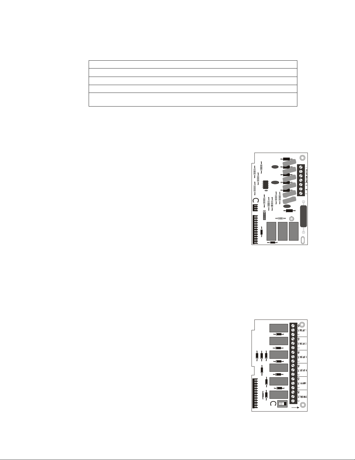
Transmitter Module - 4XTM
The Transmitter Module provides a supervised output for a Local Energy
Municipal Box transmitter and alarm and trouble reverse polarity circuits for
Remote Station Service. Also included is a DISABLE switch and disable
trouble LED.
Note: As a jumper option, the alarm reverse polarity circuit will open on trouble if no
alarm exists.
Specifications for Local Energy Municipal Box service (NFPA 72 Auxiliary
Fire Alarm System)
Supervisory current: 5.0 mA.
Trip current: 0.35 amps (subtracted from Notification Appliance
power).
Coil Voltage: 3.65 VDC.
Coil resistance: 14.6 ohms.
Maximum allowable wire resistance between panel and trip coil: 3 ohms.
Municipal Box wiring can leave the building.
TBL
J1
J2
TB1
4XTMF.cdr
10
Specifications for Remote Station Service (NFPA 72 Remote Station Fire Alarm System)
Maximum load for each circuit: 10 mA.
Reverse polarity output voltage: 24 VDC.
Remote Alarm and Remote Trouble wiring can leave the building.
Zone Relay Module - 4XZM
The Zone Relay module provides Form-C contacts for the following:
• Relay #1 - Alarm Detected / First Alarm
• Relay #2 - Alarm Detected / Second Alarm
• Relay #3 - Release 1 / Release 1
• Relay #4 - Release 2 / Not Used
• Relay #5 - General Alarm
• Relay #6 - System Trouble
Note: As a jumper option, the first four relays can be made silenceable.
Specifications
Dry Form-C contacts rated: 2.0 amps @ 30 VDC (resistive), 0.5 amps @ 30
VAC (resistive).
PDRP-1002 Instruction Manual PN 51135:B0 04/06/01
J2
LATCH
TB1
DISABLE
4XZMF.cdr
Page 11
Options 1. Product Description
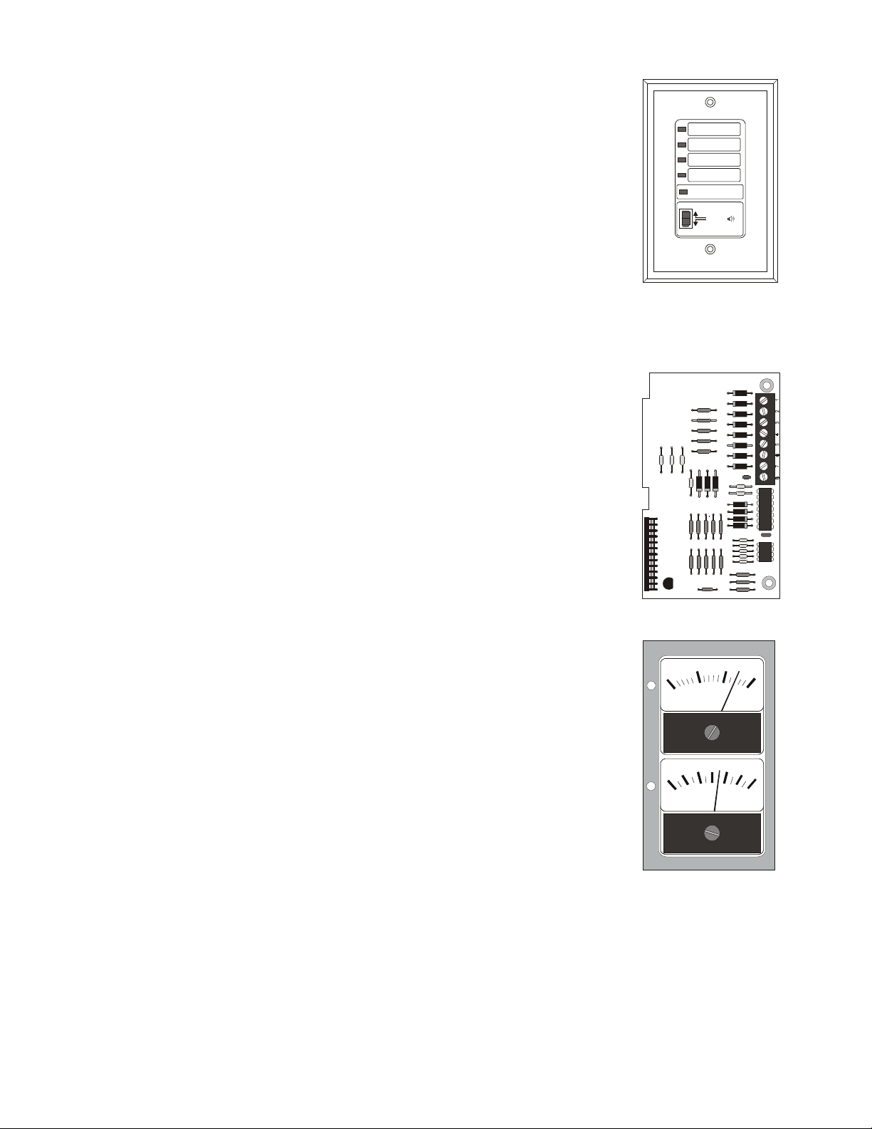
Remote Annunciator - RZA-4X
The Remote Annunciator mounts on a standard single-gang box, and provides
LED indication of the same functions as the zone relay module. For example,
with DIP switch #1 ‘ON’ and DIP switch #2 ‘OFF’:
• One zone in alarm (red)
• Two zones in alarm (red)
• Releasing Circuit 1 (red)
• Releasing Circuit 2 (red)
• System Trouble (yellow)
A local trouble sounder and silence switch are also provided. All LED wiring
is supervised for open conditions. Any open condition will cause the System
Trouble LED to illuminate. Slide-in paper labels permit an easy change of zone information.
Note: The Remote Annunciator requires the use of an LED Interface Module as described below.
SYSTEM TROUBLE
RE-SOUND
TONE
SILENCE
FIRE ALARM ANNUNCIATOR
RXA-4XF.cdr
LED Interface Module - 4XLM
The LED Interface Module supports the RZA-4X Remote Annunciator
Module. Annunciator wiring is supervised for open conditions by this module.
The module mounts to the main board on the J8 option connector.
Specifications
Maximum voltage/current, each output: 27.6 V / 8 mA.
Outputs are power-limited.
Meter Module (Volts-Amps) - 4XMM
The Meter Module provides a voltmeter to measure the voltage across the
batteries and an ammeter to measure the charging current to the batteries. The
meters are provided as an assembly that mounts to the lower left-hand corner
of the cabinet.
J2
0
3
10 20
DC VOLTS
0
TB1
4XLMF.cdr
30
3
PDRP-1002 Instruction Manual PN 51135:B0 04/06/01
DC AMPERES
4XMMF.cdr
11
Page 12

1. Product Description Specifications
Specifications
AC Power
PDRP-1002: 110/120 VAC, 50/60 Hz, 1.2 amps
PDRP-1002E: 220/240 VAC, 50/60 Hz, 0.6 amps
Wire size: minimum #14 AWG with 600V insulation
Battery (lead acid only)
Maximum Charging Circuit: 27.6V, 1.5 amps
Maximum Battery Capacity: 18 AH.
Note: Batteries larger than 12 AH require Fire•Lite BB-17 or other UL-listed external battery cabinet.
Initiating Device Circuits
Power-limited circuitry
Operation: Style B (Class B) or Style D (Class A)
Normal Operating Voltage: 24 VDC (ripple = 1.0V p-p)
Alarm current: 15 mA minimum
Short circuit current: 40 mA maximum
Maximum detector current in standby: 2 mA (max) per zone
Maximum loop resistance: 100 ohms
End-of-Line Resistor: 4.7K, 1/2-Watt (part # 71252 UL listed)
Detector loop current is sufficient to ensure operation of one alarmed detector per zone.
Supervisory current: 5 mA (including End-of-Line Resistor)
Notification Appliance and Releasing Circuits
Power-limited circuitry
Maximum allowable voltage drop due to wiring: 2 VDC
Normal Operating Voltage: 24 VDC
Total current available to all external devices: 2.25 amps
Maximum signaling current per circuit: 1.5 amps
End-of-Line Resistor: 4.7K, 1/2-Watt (part # 71252 UL listed)
Alarm and Trouble Relays
Dry Form-C contacts rated: 2.0 amps @ 30 VDC (resistive), 0.5 amps @ 30 VAC (resistive).
Note: Any power connected to these relay contacts must come from a power-limited supply. Fail-safe operation
ensures trouble relay functioning under loss of both primary power (AC) and secondary (battery power).
Resettable Power
Up to 200 mA is available for powering four-wire smoke detectors. Maximum ripple voltage: 1.0 V p-p.
Nonresettable Power
Total DC current available from this output is up to 200 mA (subtracted from four-wire smoke detector
power). Maximum ripple voltage: 1.0 V p-p.
RMS Regulated Power
12
Total DC current available for powering external devices is 0.5 amp (subtracted from 2.25 amps available
to Notification Appliance Circuits). Maximum ripple voltage: 100 mV p-p.
PDRP-1002 Instruction Manual PN 51135:B0 04/06/01
Page 13

Cabinet Mounting
Carefully unpack the system and check for shipping damage.
Select a suitable location in a clean, dry, vibration-free environment that is not subject to extreme
temperatures. Locate the top of the cabinet approximately five feet above the floor with the hinge on the
left. The panel must be easily accessible for maintenance; the hinged door requires a minimum clearance
of 14 in. (35.56cm) to open.
Removal of Circuit Board
To prevent damage to the printed circuit board it should be removed prior to mounting of cabinet.
Step Action
1
Disconnect the transformer wires from the circuit board at the J1
connector.
2
Remove the four (4) phillips head screws securing circuit board to
backbox rails.
3
Carefully set board aside in a secure place.
2. Installation
Mounting of Cabinet
Securely mount the cabinet using the mounting holes provided.
Step Action
1 Mark and predrill holes for the top two keyhole mounting screws using the
dimensions shown in Figure 2 on page 14.
2 Install two upper screws in the wall with the heads protruding.
3 Using the upper keyholes, mount the backbox over the two screws.
4 Mark and drill the lower two holes.
5 Secure backbox by installing the remaining fasteners and tightening all
screws.
6
If required, attach optional Trim Ring (TR-4XRF) using the provided
instructions.
Attaching Conduit
Select and remove knockouts according to the number of conduits required.
Attach conduits to backbox as required.
Determine the number of conductors required for the devices to be employed. Pull required conductors
into the box through the knockouts provided.
Note: All wiring should be in accordance with the National and/or Local codes for fire alarm systems, including
"Power-limited Wiring Requirements" on page 17.
PDRP-1002 Instruction Manual PN 51135:B0 04/06/01
13
Page 14
2. Installation Cabinet Mounting
(
)
(
)
(
)
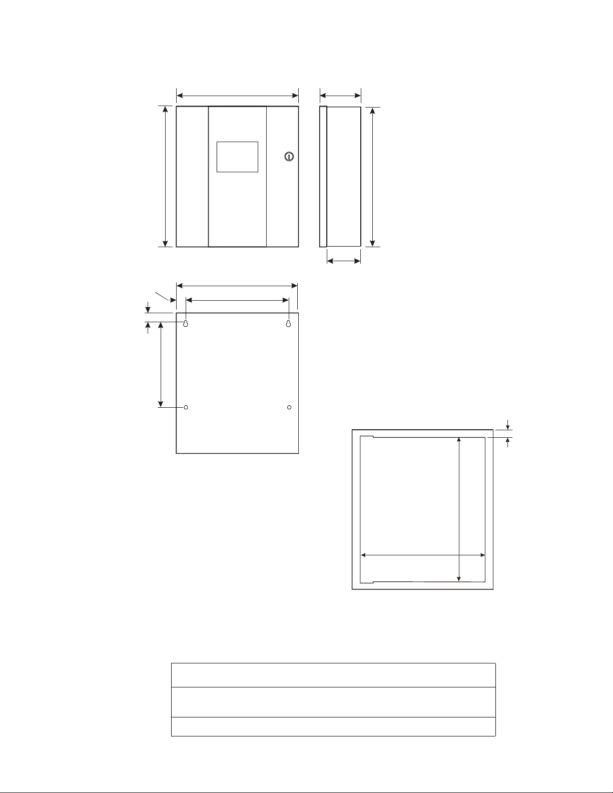
The figure below shows the exterior dimensions and mounting hole locations for the cabinet backbox and
dimensions of the optional trim ring:
16.125”
(40.96cm )
1.00”
(2.54cm )
1.00”
(2.54cm )
9.50”
(24.13cm )
14.50”
(36.83cm )
14.625”
(37.15cm )
12.50”
(31.75cm )
5.375”
(13.65cm )
4.75”
(12.07cm )
16.00”
(40.64cm )
MS44-cabdim.cdr
Figure 2 Cabinet Mounting Dimensions
Reinstallation of Circuit Board
Reinstall the printed circuit board as follows:
Step Action
1 Position circuit board over stand-offs on backbox rail and secure with four
(4) phillips screws. Tighten securely.
14.625”
37.15cm
16.125”
40.96cm
1.5”
3.81cm
MS44-trimring.cdr
2 Connect transformer wires to J1 connector on circuit board.
14
PDRP-1002 Instruction Manual PN 51135:B0 04/06/01
Page 15
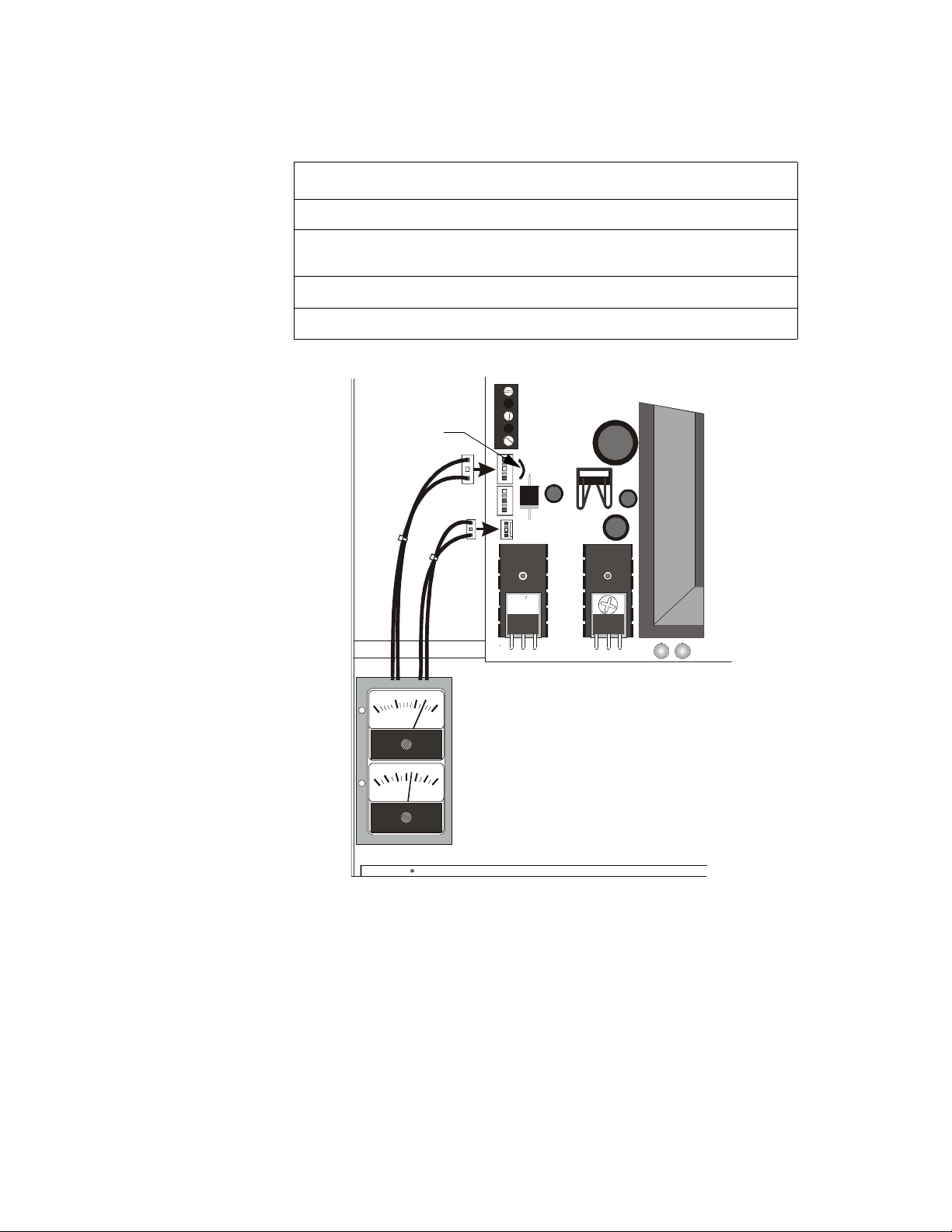
Installing Optional Voltmeter/Ammeter 2. Installation
Installing Optional Voltmeter/Ammeter
To monitor battery voltage and battery charging current, a 4XMM Meter Module is required. To install
the power meter module follow the steps below:
Step Action
1
Cut the jumper wire labeled “AMP”.
2 Secure the module to the backbox with the hardware provided. Refer to
Product Installation Drawing (PID) for detailed instructions.
3
Connect meter cable P2 to connector J2 on the main circuit board.
4
Connect meter cable P3 to connector J3 on the main circuit board.
The figure below shows the mounting location and connections for the Voltmeter/Ammeter.
TB5
‘AMP’ Jumper
J2
AMP
J9
J3
10 20
DC VOLTS
0
30
3
0
3
DC AMPERES
Figure 3 Mounting and Connecting the Meters
MS44-mminst.cdr
PDRP-1002 Instruction Manual PN 51135:B0 04/06/01
15
Page 16
2. Installation Power Connections
Power Connections
WARNING: Do not apply any type power to this control panel until all connections have been
!
made and verified.
AC Connections
Disconnect (open) the circuit breaker in the AC main breaker panel and tag it “Out of Service”.
Note: Refer to "Power-Up Procedure" on page 31 before closing AC breaker.
Primary power required for the PDRP-1002 control panel is 110/120 VAC, 50/60 Hz, 1.2 amps and for
the PDRP-1002E is 220/240 VAC, 50/60 Hz, 0.6 amps.
Overcurrent protection for this circuit must comply with Article 760 of the National Electrical Code (NEC)
and/or local codes. Use #14 AWG (2.00 mm
2
) or larger wire with 600V insulation rating.
A separately fused and protected power connection to the panel should be supplied to prevent voltage
fluctuation and interruption of power.
Ground
Neutral
Hot
TB5
J2
AMP
J9
J3
MS44-ACconn.cdr
16
Figure 4 AC Power Connections
Battery (DC) Connections
WARNING: Battery contains sulfuric acid which can cause severe burns to the skin and eyes and
!
can destroy fabrics. If contact is made with sulfuric acid, immediately flush the skin or eyes with
water for 15 minutes and seek immediate medical attention.
CAUTION: Do NOT connect the battery interconnect wire at this time. Make this connection AFTER
!
initial system primary power connection.
Place batteries into bottom of cabinet as shown below. See "Appendix A: Secondary Power Calculations"
on page 39 for calculation of correct battery rating.
Note: Batteries are shipped separately and should be mounted only after the cabinet has been installed, the conduit
connected, and all wiring pulled, tested, and made ready to be terminated.
Continued on the next page...
PDRP-1002 Instruction Manual PN 51135:B0 04/06/01
Page 17
Power-limited Wiring Requirements 2. Installation
Observe polarity when connecting the batteries. Connect the battery cable (p/n 75203 or 75202, depending
on terminal size of battery) to terminal J9 on the main circuit board using the plug-in connector provided.
Connect red wire to positive (+) terminal and black wire to negative (–) terminal on opposing batteries.
Do NOT connect battery interconnect wire at this time.
TB5
J2
AMP
J9
J3
Figure 5 Battery Installation and Connection
Power-limited Wiring Requirements
Power-limited and nonpower-limited circuit wiring must remain separated in the cabinet. All powerlimited circuit wiring must remain at least 0.25 in (6.35 mm) away from any nonpower-limited circuit
wiring. Furthermore, all power-limited circuit wiring and nonpower-limited circuit wiring must pass
through separate knockouts and/or conduits.
Power-limited
Circuits
Nonpower-limited
Circuits
B+ A+ A– B–
TB1
J1
TB5
J2
AMP
J9
J3
MS44-BATconn.cdr
Power-limited Circuits
OUT#4
ALARM
IN # 1
IN # 2
IN # 3
OUT#1
OUT#3
OUT#2
B+ B–
B+ B–
AC POWER
SYSTEM
ALARM
ALARM TEST
SUPERVISORY
SYSTEM
TROUBLE
CIRCUIT
TROUBLE
ALARM
SILENCED
POWER
TROUBLE
TONE
SILENCE
ALARM
SILENCE
NO NC C
B+ A+ A– B–
TB3
TB2
JP1
GEN
SUPV 1
ALM1
SUPR 2
GEN
ALM2
ZONE 1
ZONE 2
ZONE 3
ZONE 4
ALARM
SYSTEM
ACTIVATE
RESET
SW1
B+ A+ A– B–
B+ A+ A– B–
J4
TBL
J5
J7
J8
B+ A+ A– B–
J1
J2
J10
J2
IN # 4
B+ A+ A– B–
TB4
TB1
POWER LIMITED
7 6 5 1
OPT1
TB1
Power-limited
Circuits
OPT2
Nonpower-limited
Circuits
DISABLE
LATCH
AC Power
PDRP-1002 Instruction Manual PN 51135:B0 04/06/01
MRP44-plwiring.cdr
Figure 6 Power-limited Wiring Requirements
17
Page 18
2. Installation Initiating Device Circuits
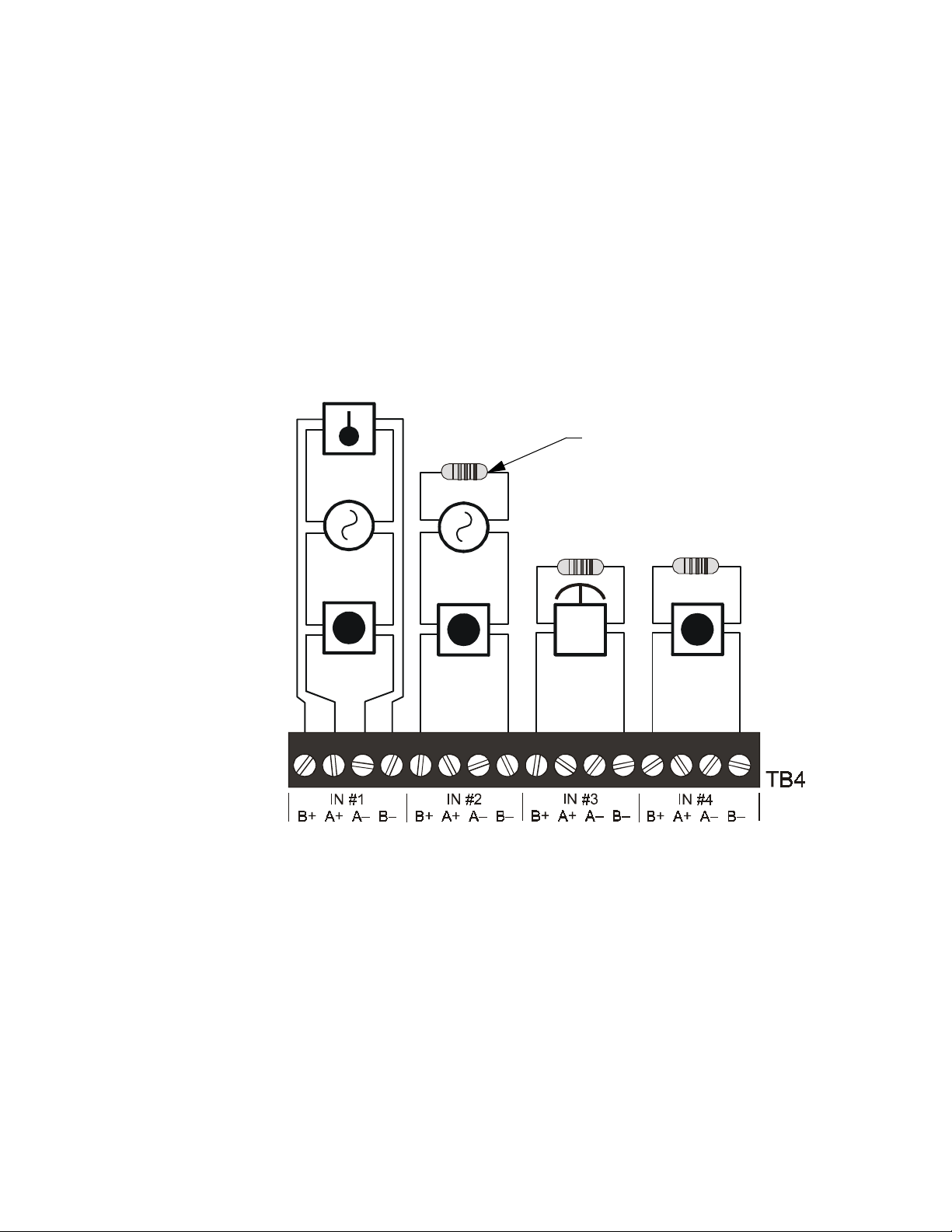
Initiating Device Circuits
The control panel provides two Initiating Device Circuits (#1 and #2) and they may be configured as either
Style D (Class A) or Style B (Class B). Circuit #3 is designated as an Abort Switch Circuit and Circuit #4
is a Manual Release Circuit.
Initiating devices include: Heat, Photoelectric and Ionization type detectors, Manual Pull Stations and
Waterflow alarm devices.
Note: Refer to "Appendix B: Compatible Devices" on page 41 for compatible devices.
• Wire all alarm initiating devices sequentially for proper supervision.
• Observe polarity when connecting polarized devices.
• All circuits are supervised and power-limited.
• Leave dummy load resistor (provided) on all unused circuits.
Style D (Class A)
Initiating Device
Circuit
Heat
Detector
Two-wire
Smoke
Detector
Manual
Pull Station
Style B (Class B)
Initiating Device
Circuit
Style B (Class B)
Note: Silk screen printing on circuit board moved to bottom for clarity
4.7K, 1/2-Watt resistor
PN 71252 (UL listed)
Abort Switch
Circuit
Style B (Class B)
Manual Release
Circuit
MRP44-idc.cdr
18
Figure 7 Initiating Device Circuits
PDRP-1002 Instruction Manual PN 51135:B0 04/06/01
Page 19
Initiating Device Circuits 2. Installation
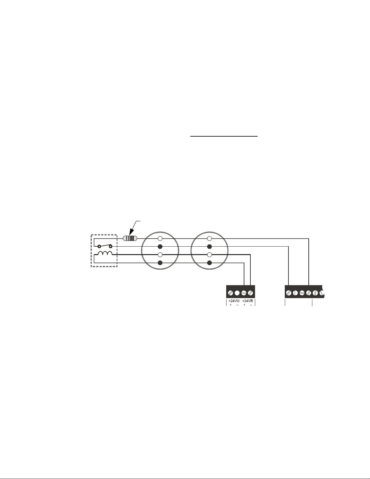
Four-Wire Smoke Detector Connections
A maximum of 200mA is available from the 24VDC Resettable Power circuit on TB1 (+24VR terminals).
Any power that is drawn from the 24VDC Nonresettable Power on TB2 (+24VNR terminal) must be
subtracted from available resettable power. See "Specifications" on page 12 and "Powering External
Devices" on page 22.
Note: Refer to "Appendix B: Compatible Devices" on page 41 for suitable 4-wire smoke detectors.
Notes on Style D (Class A) and Style B (Class B) field wiring:
1. The Power Supervision Relay coil leads must be connected to the last detector base 24V screw
terminals.
2. Calculation of the maximum allowable resistance in the 24VDC resettable power wiring:
Rmax =
(20.6 - Vom)
(N x Is) + (Na x Ia) + (Ir)
Where:
Rmax = maximum resistance of the 24 VDC wires
Vo m = minimum operating voltage of the detector or end-of-line relay, whichever is greater, in volts
N = total number of detectors on the 24 VDC supply circuit
Is = detector current in standby
Na = number of detectors on the 24 VDC power circuit which must function at the same time in alarm
Ia = detector current in alarm
Ir = end-of-line relay current
4.7K, 1/2-Watt ELR
–
+
–
+
TB1
Control Panel
Power Circuit
IN #1
B+ A+ A– B–
Initiating Device Circuit
Style B
IN
B+ A+
TB4
Power
Supervision
Relay
(A77-716B)
–
+
–
+
24 VDC Four-wire
Smoke Detectors
MS44-4wiresd.cdr
PDRP-1002 Instruction Manual PN 51135:B0 04/06/01
Figure 8 Typical Connection for Four-Wire Smoke Detectors
19
Page 20
2. Installation Output Circuits
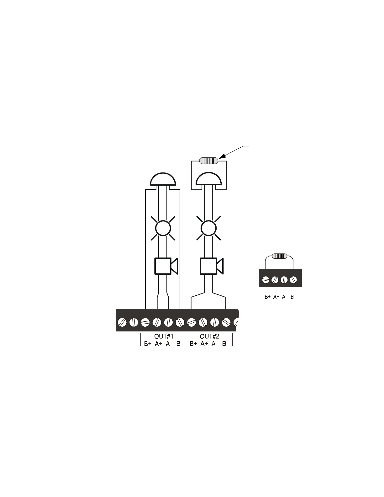
Output Circuits
Notification Appliance Circuits
The control panel provides two Style Z (Class A) or Style Y (Class B) Notification Appliance Circuits,
which are supervised and power-limited.
Each circuit is capable of 1.5 amps of current. Total current drawn from both NACs and both Releasing
Circuits (see "Releasing Circuits" on page 21) cannot exceed 2.25 amps.
Note: Refer to "Appendix B: Compatible Devices" on page 41 for suitable devices.
• For DIP switch configuration, see "Setting Mode of Operation" on page 28.
• For non-silenceable service on NAC#1, see "Non-Silenceable Service" on page 36.
• Unused circuits must be connected with a dummy load as shown.
Polarized
Bell
Polarized
Strobe
Polarized
Horn
Style Z
(Class A)
Style Y
(Class B)
4.7K, 1/2-Watt ELR
(PN 71252)
Unused Style Y Circuit
(4.7K, 1/4-Watt ELR)
TB2
20
MRP44-nac.cdr
Figure 9 Notification Appliance Circuits
PDRP-1002 Instruction Manual PN 51135:B0 04/06/01
Page 21
Output Circuits 2. Installation
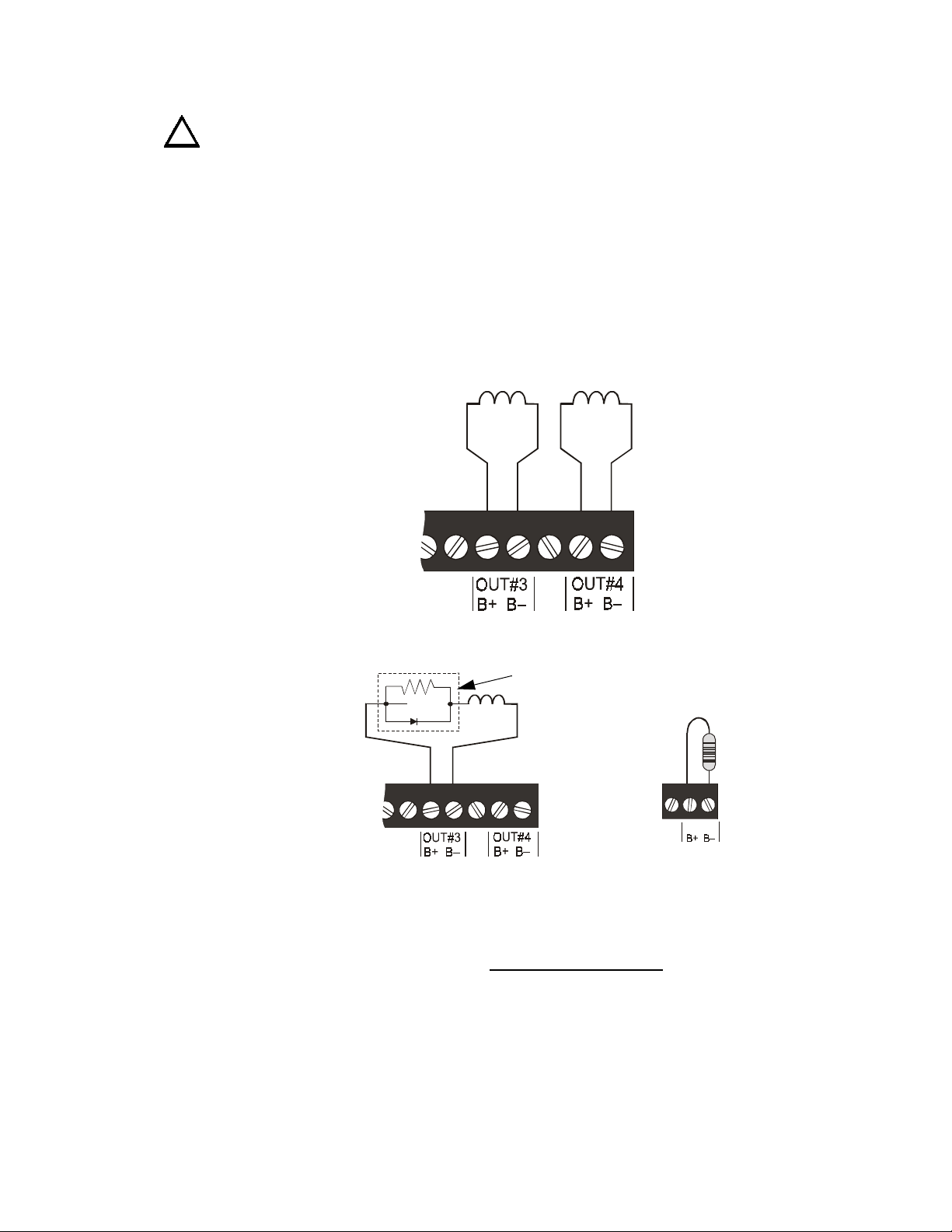
Releasing Circuits
CAUTION: To prevent accidential discharge, connect releasing devices after initial panel tests are
!
completed.
The control panel provides two Style Y (Class B) Releasing Circuits, which are nonpower-limited.
Circuit #2 can be configured for a Supervisory Circuit (see "Setting Mode of Operation" on page 28) and
will then be power-limited.
Note: All wiring must follow the requirements as specified under "Power-limited Wiring Requirements" on page 17.
Each circuit is capable of 1.5 amps of current. Total current drawn from both Releasing Circuits and both
NACs (see "Notification Appliance Circuits" on page 20) cannot exceed 2.25 amps.
• UL listed and FM approved releasing devices must be used.
• Unused circuits must be connected with a dummy load as shown.
Releasing
Circuit #1
Releasing
Circuit #2
TB2
Canadian Applications
REL-4.7K
Unused
Releasing
Circuits
TB2
MRP44-rel.cdr
Figure 10 Releasing Circuits
Wiring must be configured to maintain a minimum voltage of 20.4 VDC on releasing Circuits. Calculation
of maximum allowable resistance:
Rmax =
20.6 VDC – 20.4 VDC
Is
Where:
Rmax = maximum allowable resistance of wiring
Is = Solenoid current
PDRP-1002 Instruction Manual PN 51135:B0 04/06/01
21
Page 22
2. Installation Powering External Devices
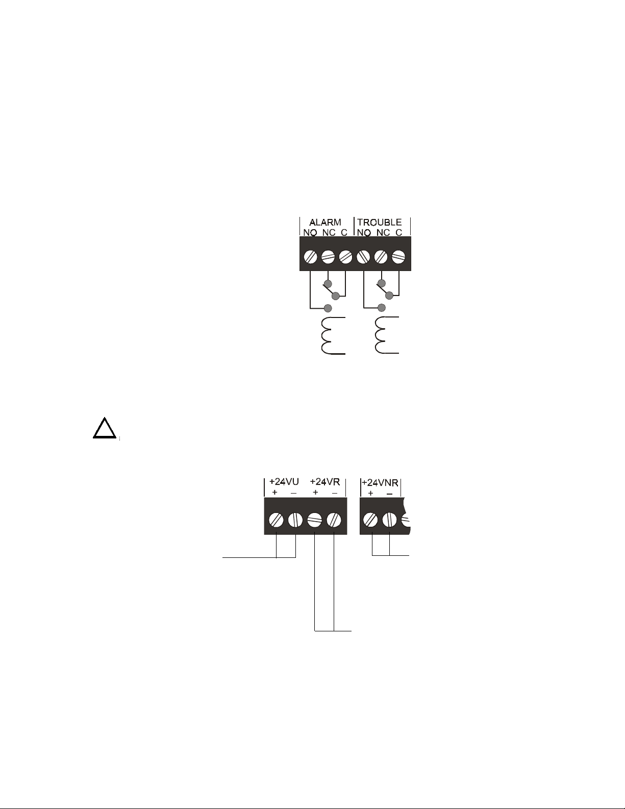
Alarm Relay Circuit
One Form-C dry contact alarm relay is provided in the basic panel for controlling supplementary devices.
Contacts are rated 2 amps at 30 VDC and 0.5 amps at 30 VAC (resistive) and are non-silenceable when
an alarm occurs.
Trouble Relay Circuit
One Form-C dry contact trouble relay is provided in the basic panel for controlling supplementary devices.
It is rated 2 amps at 30 VDC and 0.5 amps at 30 VAC (resistive) and will restore to normal when the trouble
condition is cleared.
Note: Power connected to these relay contacts must come from a power-limited supply. Power may be obtained from
TB1 Terminals 24VU or 24VR and TB2 Terminals 24VNR, or a UL-listed power-limited power supply.
TB3
Figure 11 Schematic Representation of Alarm/Trouble Coils & Contacts
Powering External Devices
CAUTION: Several different sources of power can be connected to this panel. Disconnect all sources
!
of power before servicing. The panel and associated equipment may be damaged by removing and/or
!
!
inserting cards, modules, or interconnecting cables while this unit is energized.
DC power connections are available from TB1 and TB2 on the control panel as shown below:
RMS-Regulated Power -
24 VDC power for inductive-type
devices such as door holders can
be connected to these terminals.
This output is not suitable for
powering devices requiring
filtered DC power.
TB1
MS44-relay.cdr
TB2
MS44-dcpower.cdr
Nonresettable Power -
24 VDC filtered, nonresettable power
can be drawn from these terminals.
The combined current draws from the
Resettable and Nonresettable outputs
cannot exceed 200 mA.
Resettable Power -
24 VDC filtered, resettable power for four-wire smoke
detectors can be obtained from these terminals.
The combined current draws from the Resettable and
Nonresettable outputs cannot exceed 200 mA.
22
Figure 12 Power Terminals
PDRP-1002 Instruction Manual PN 51135:B0 04/06/01
Page 23
Optional Modules 2. Installation
Optional Modules
Overview
The control panel has two module connectors - J5 (upper position) and J8 (lower position). Three modules
are available for the panel and they can be used in any combination, including duplicate modules. The
corresponding option jumper must be cut before installation of an optional module, to enable module
supervision.
• The 4XTM Transmitter and 4XZM Zone Relay Modules can be installed in either position.
• The 4XLM Interface Module must be installed in the lower position only.
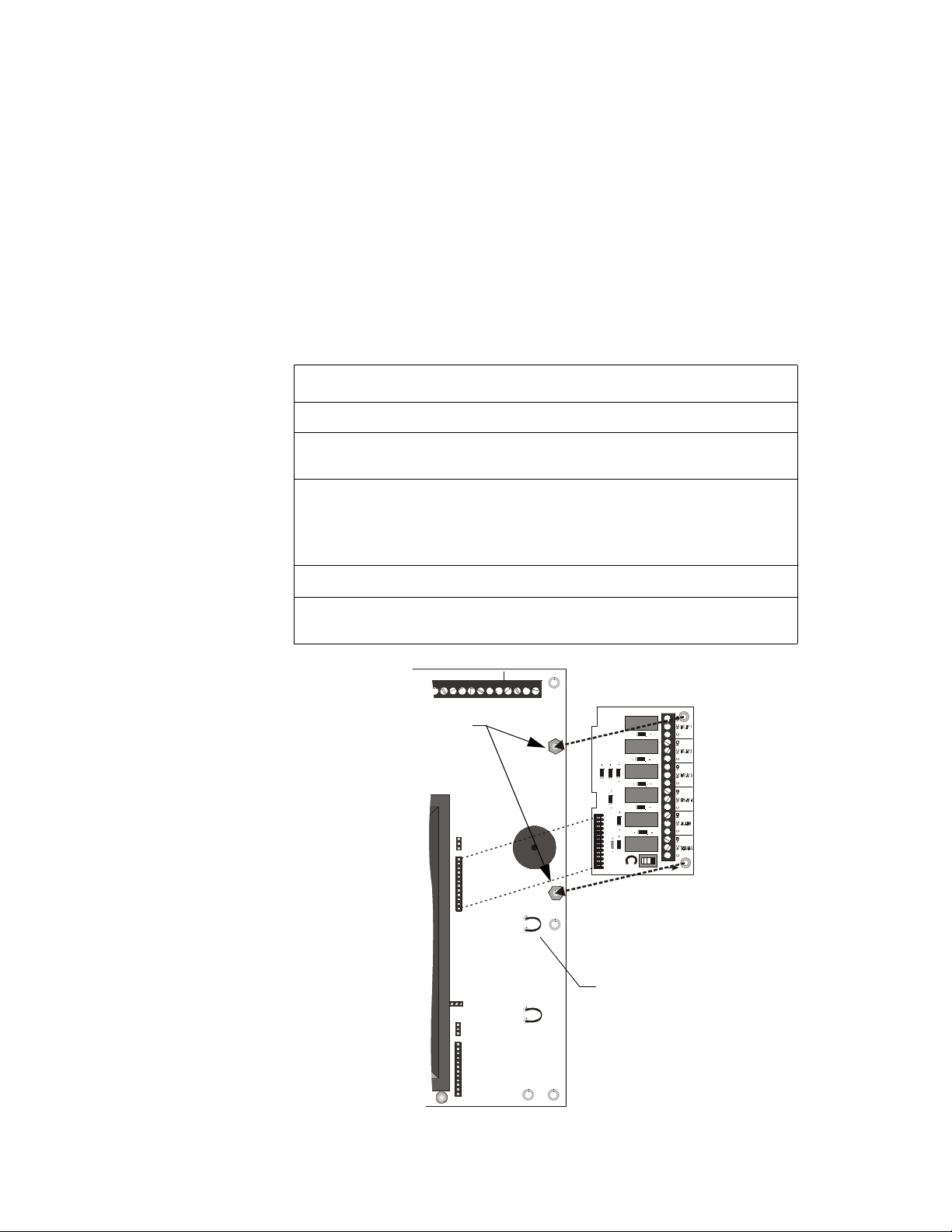
Installation - Upper Position
To install either the 4XTM or 4XZM module in the upper position follow these instructions:
Step Action
1 Cut jumper ‘OPT1’ on main circuit board.
2 Insert the two stand-offs into the holes located on the right-side edge of the
main board. Secure with nuts and tighten securely.
3
Align the pins of J5 (and J4) connectors on the main board with the
holes on the underside of the J2 (and J1) connector on the optional
board. Carefully press down on the optional board until the pins are
through the connectors and it rests on the stand-offs.
4
Secure optional board to stand-offs with screws. Tighten securely.
5 Affix the terminal identification label (provided with the module) on the
back surface of the backbox, aligning it with the terminals on the module.
Install Stand-offs here
B–
IN # 2
B+ A+ A– B–
B+ A+ A– B–
J4
J5
J10
J7
J8
IN # 3
IN # 4
B+ A+ A– B–
TB4
J2
OPT1
LATCH
TB1
DISABLE
OPT1 - Cut prior to
OPT2
installation of module
PDRP-1002 Instruction Manual PN 51135:B0 04/06/01
MS44-instmod1.cdr
Figure 13 Module Installation - Upper Position
23
Page 24
2. Installation Optional Modules
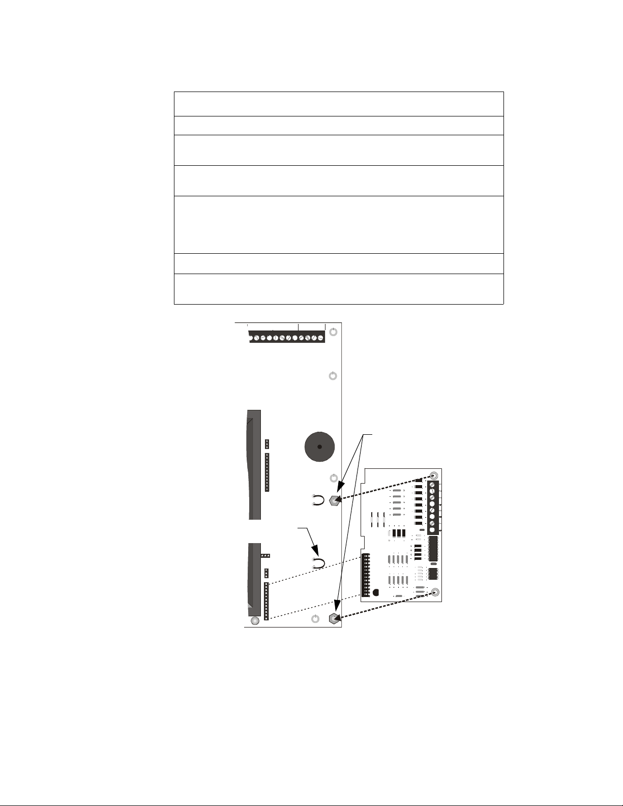
Installation - Lower Position
To install either the 4XTM, 4XZM or 4XLM module in the lower position follow these instructions:
Step Action
1 Cut jumper ‘OPT2’ on main circuit board.
2 Remove the lower-right screw securing the main board to the lower rail.
Replace with a stand-off and tighten securely.
3 Insert one stand-off into the other hole located on the right-side edge of the
main board. Secure with nut and tighten securely.
4
Align the pins of J8 (and J7) connectors on the main board with the
holes on the underside of the J2 (and J1) connector on the optional
board. Carefully press down on the optional board until the pins are
through the connectors and it rests on the stand-offs.
5
Secure optional board to stand-offs with screws. Tighten securely.
6 Affix the terminal identification label (provided with the module) on the
back surface of the backbox, aligning it with the terminals on the module.
IN # 2
IN # 3
B–
B+ A+ A– B–
B+ A+ A– B–
IN # 4
B+ A+ A– B–
TB4
J4
J5
TB1
OPT1
OPT2 - Cut prior to
installation of module
Install Stand-offs here
J10
J7
J8
OPT2
J2
Figure 14 Module Installation - Lower Position
MS44-instmod2.cdr
24
PDRP-1002 Instruction Manual PN 51135:B0 04/06/01
Page 25
Optional Modules 2. Installation
Setup and Configuration
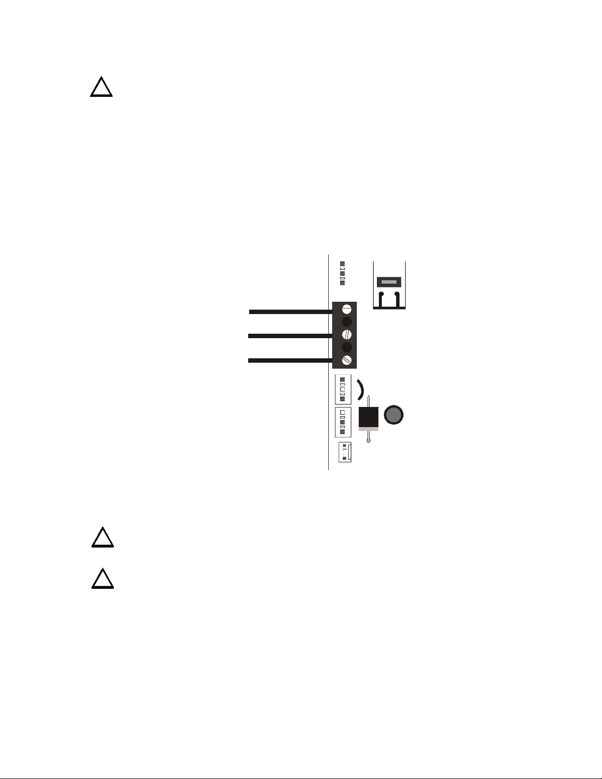
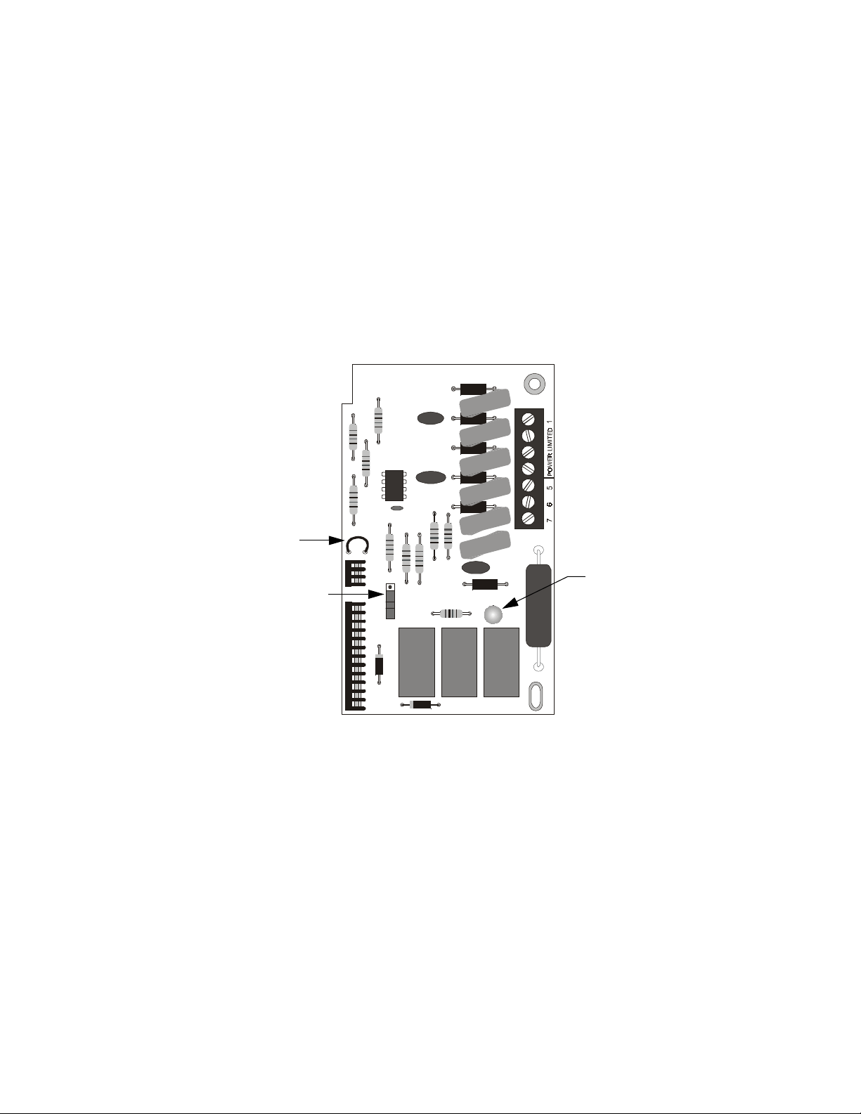
Transmitter Module - 4XTM
Connect a Remote Alarm circuit, Remote Trouble circuit or a Municipal Box to the Transmitter Module
as shown below. Polarities shown in activated positions.
Note: Dummy load terminals 6 and 7 (4.7K, 1/4 W resistor) if Municipal Box is not connected.
Note: Remote Alarm, Remote Trouble and Municipal Box wiring can leave the building.
Pushing the Disconnect Switch down will prevent unwanted activation of the Municipal Box during testing
of the control panel. The Disconnect LED will remain illuminated while the Municipal Box is
disconnected. The System Trouble LED will indicate disconnected and/or Open Circuit conditions on the
Municipal Box.
Cut the TBL Jumper to allow the alarm reverse polarity circuit to open on trouble, if no alarm exists.
The wiring of this module must follow the requirements as specified under "Power-limited Wiring
Requirements" on page 17.
TB1
+
Remote Alarm (Power-limited)
–
+
Remote Trouble (Power-limited)
–
No Connection
+
Municipal Box (Nonpower-limited)
–
TBL Jumper
TBL
Disconnect Switch
J1
J2
Figure 15 4XTM Configuration
Disconnect LED
4XTMF.cdr
PDRP-1002 Instruction Manual PN 51135:B0 04/06/01
25
Page 26

2. Installation Optional Modules
Zone Relay Module - 4XZM
Relay #1 through #4 on this module have specific functions based on the configuration of DIP switches
#1 and #2 on the control panel. See “Zone Relay Module Configuration” on page 30 for a more detailed
explaination of the conditions that will activate each relay under the different DIP switch setings.
For non-latching (silenceable) relay operation, cut the jumper “LATCH”. If this jumper is left intact, the
relays will latch upon activation. To disconnect relays entirely, slide the disable switch to the right.
Note: If any dry contacts are to be used as nonpower-limited circuits, write this on the Protected Premises Unit label,
located on the door of the control panel.
TB1
J2
LATCH
DISABLE
4XZMF.cdr
Disable Switch“Latch” Jumper
Figure 16 Wiring the Zone Relay Module
The wiring of this module must follow the requirements specified under "Power-limited Wiring
Requirements" on page 17.
• If this module is used to drive both nonpower-limited and power-limited circuits, skip one set of
dry contacts to maintain the required separation between circuit types.
• If this module is used to drive both nonpower-limited and power-limited relays that are next to each
other, refer to the figure below which shows the one allowable arrangement.
Power-Limited
Circuit
26
No Connection
Nonpower-Limited
Circuit
MS44--4xzmf1.cdr
Figure 17 Mixing Power-Limited and Nonpower-Limited Circuits
PDRP-1002 Instruction Manual PN 51135:B0 04/06/01
Page 27

Optional Modules 2. Installation
LED Interface Module - 4XLM
Connect the terminals on TB1 of the LED Interface Module to the corresponding terminals of the RZA4X Remote Annunciator.
Make wiring connections with system power off.
Maximum wire impedance is 50 ohm per wiring connection.
The wiring of this module must follow the requirements as specified under "Power-limited Wiring
Requirements" on page 17.
TB1
+24V
Out #1
Out #2
Out #3
Out #4
Sysyem Trouble
Sound
Resound
J2
Connect to corresponding
terminals of the RZA-4X
Remote Annunciator.
SYSTEM TROUBLE
RE-SOUND
TONE
SILENCE
FIRE ALARM ANNUNCIATOR
Front View
Side View
Figure 18 Connection of 4XLM to RZA-4X
Single-gang
Box
MS44--4xlmfconn.cdr
PDRP-1002 Instruction Manual PN 51135:B0 04/06/01
27
Page 28

2. Installation Setting Mode of Operation
Setting Mode of Operation
Select operating mode by setting the SW1 DIP switches as described below; basic programming options
are shown in this section.
After any changes are made to the configuration of the switches, the panel must be reset.
For Canadian use, refer to "Sprinkler Supervisory Tracking" on page 36.
SW1
MS44-dipsw.cdr
Basic Programming
Switch 1: Cross Zone
Switch 2: Supervisory
Abort Options
Switch 3: Delay Timer
Switch 4: Delay Timer
Delay Timer
Switch 5: Abort Option
Switch 6: Abort Option
Figure 19 DIP Switch Settings
DIP Switch Functions
Switch #1 - Cross Zone
Select the desired mode of operation and set switch per appropriate column:
OFF ON
NAC #1 Activated by an alarm in either
IDC # 1 or IDC #2.
NAC #2 Activated by an alarm in either
IDC #1 or IDC #2.
Note: The NAC will pulse at 60 ppm
while timer is running or frozen by
abort and will sound steady upon
release (time out).
NAC #1 Pre-discharge Alarm
the first alarmed zone in the system.
Initiation of an alarm on the other
zone will shut this output off
NAC #2 Activated when alarms occur on
both IDC #1 or IDC #2.
Note: The NAC will pulse at 60 ppm
while timer is running or frozen by
abort and will sound steady upon
release (time out).
- Activated by
28
REL #1
REL #2
Will be activated when the timer expires (provided that REL #2 is functioning as a
releasing circuit - set via DIP switch #2)
The Releasing Circuit Delay Timer will start
whenever an alarm occurs on either IDC #1 or
IDC #2.
The Releasing Circuit Delay Timer will start
whenever an alarm occurs on both IDC #1 or
IDC #2.
PDRP-1002 Instruction Manual PN 51135:B0 04/06/01
Page 29

Setting Mode of Operation 2. Installation
Switch #2 - Supervisory/Releasing Service
Set the function of Releasing Circuit #2 by setting this switch.
OFF ON
REL #2 Will function as a solenoid releasing
circuit.
Note: This circuit is nonpowerlimited.
REL #2 Will function as a supervisory input
circuit.
• A short condition on this circuit
• An open condition generates a
Note: This circuit will now be powerlimited.
Switch #3 and #4 - Timer Delay
Select the desired timer setting and set these switches accordingly.
No Delay* 10 Second 20 Second 30 Second
Switch #3
Switch #4
OFF OFF ON ON
OFF ON OFF ON
* Abort timer will not operate when timer is set for ‘No Delay’.
will light the Supervisory LED
and sound the supervisory tone on
the control panel piezo.
circuit trouble condition.
Switch # 5 and #6 - Abort Function
Select the desired Abort Functions for delaying the activation of releasing circuits, and set these switches
accordingly. If ‘Cross Zone’ is selected, both IDC #1 and IDC #2 must be activated to start timer.
Switch #5
Switch #6
OFF OFF ON ON
OFF ON OFF ON
Standard UL-type
delay timer
Continues to count
down upon ABORT, but
stops and holds at 10
seconds until release of
the ABORT switch.
Upon release of the
ABORT switch, the
timer resumes the
countdown at 10
seconds.
These modes are the only ones that
comply with UL Standard 864.
Note: Abort timer will not operate when timer is set for ‘No Delay’. Manual pull station does not use
abort mode.
IRI-type delay
timer
Functions the same as
the UL-type timer with
the exception that the
ABORT will function
only if pressed and held
before 2nd zone goes
into alarm.
NYC-type delay
timer
When an alarm exists,
pressing ABORT
changes timer value to
the Timer Delay plus 90
seconds. The timer will
not start while ABORT
is held. SYSTEM
RESET restores timer to
origional Timer Delay.
Each time ABORT is
pressed again adds 90
seconds to Timer Deley.
Local Jurisdiction
delay timer
Once the timer has
started, pressing
ABORT resets the timer
to full Timer Delay. The
timer will not start
while ABORT is held.
Releasing the ABORT
switch continues the
countdown; pressing
ABORT again restores
Timer Delay to its full
value.
PDRP-1002 Instruction Manual PN 51135:B0 04/06/01
29
Page 30

2. Installation Setting Mode of Operation
Zone Relay Module Configuration
Relay #1, #2, #3 and #4 of the the 4XZM Zone Relay Module have specific functions based on the
configuration of DIP Switches #1 and #2 on the control panel. The table below provides a description of
these functions.
DIP #1 is OFF
(Either Zone)
Relay #1
Relay #2
Relay #3
Relay #4
Note: Relay #5 is reserved for General Alarm and Relay #6 is reserved for System Trouble.
Activate when alarm
is detected in
Zone #1 or Zone #2
Activates when
Release 1 is activated
Activates when
Release 2 is activated
DIP #1 is ON
(Cross Zone)\
Activates when first
alarm is detected in
the system
Activates upon
second alarm
Activates when
Release 1 is activated
Activates when
Release 2 is activated
DIP #2 is ON (Supervisory)
Either Zone Cross Zone
Same
Same Same
Not Used Not Used
Same
Same
30
PDRP-1002 Instruction Manual PN 51135:B0 04/06/01
Page 31

Power-Up Procedure 2. Installation
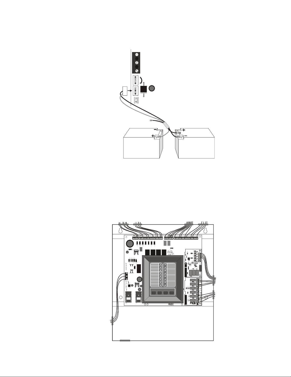
Power-Up Procedure
WARNING: Prior to energizing this panel, notify all personnel and authorities, including any
personnel who may be working on, around, or near this unit.
WARNING: Battery contains sulfuric acid which can cause severe burns to the skin and eyes and
!
can destroy fabrics. If contact is made with sulfuric acid, immediately flush the skin or eyes with
water for 15 minutes and seek immediate medical attention.
CAUTION: Observe polarity of batteries. Improper connection will cause damage and VOID
WARRANTY.
!
Follow these steps to power-up the FACP:
1. Conduct Visual Inspection. A careful visual inspection should be made before applying power to
the system. See “Inspection” on page 53.
2. Notification. Notify personnel who may be working with the AC power circuits before removing
the “Out of Service” tag.
3. Apply Primary Power. Switch the circuit breaker to the ‘closed’ position, providing power to the
circuit.
• The green AC power LED will illuminate.
• The Trouble LED will illuminate until battery power is applied.
4. Connect Secondary Power. Connect battery interconnect wire as shown below.
• The trouble LED will clear. If the trouble light does not clear, refer to "Troubleshooting Table" on
page 54.
Battery Interconnect Wire
MS44-batcable.cdr
Figure 20 Battery Connections
PDRP-1002 Instruction Manual PN 51135:B0 04/06/01
31
Page 32

2. Installation Power-Up Procedure
Notes
32
PDRP-1002 Instruction Manual PN 51135:B0 04/06/01
Page 33
WARNING: When used for CO2 releasing applications, observe proper precautions as stated in
!
NFPA 12. Do not enter the protected space unless physical lockout and other safety procedures
are fully completed. Do not use software disable functions in the panel as lockout.
System Status LEDs
Alarm, Trouble and Supervisory LEDs will flash on and off until the event(s) has been acknowledged
(TONE or ALARM SILENCE), at which point the LED will illuminate steadily.
3. System Operation
System
Status
LEDs
AC POWER
SUPERVISORY
SILENCE
BATT EARTH
SYSTEM
ALARM
RELEASE
SYSTEM
TROUBLE
CIRCUIT
TROUBLE
ALARM
SILENCED
POWER
TROUBLE
TONE
ALARM
SILENCE
ALARM
AC TIVATE
ZONE 1
ZONE 2
ABORT
MANUAUL
RELEASE
SYSTEM
RESET
MRP44-panel1.cdr
MICRO
FAIL
Figure 21 System Status LEDs
AC Power - Green LED that illuminates steadily to indicate presence of AC power.
System Alarm - Red LED that flashes when an alarm occurs.
Release - Red LED that illuminates steadily when release occurs.
Supervisory - Yellow LED that flashes upon activation of a supervisory device (such as tamper switch)
on Zone 4.
System Trouble - Yellow LED that flashes for any trouble condition, including those associated with
optional boards.
Circuit Trouble - Yellow LED that flashes for trouble conditions on output circuits (notification and
releasing).
Alarm Silenced - Yellow LED that illuminates steadily when the ALARM SILENCE switch has been
pushed after an alarm.
Power Trouble - Yellow LED that flashes for low or disconnected batteries and earth fault conditions.
The following LEDs are located below the main panel and are visible only when the panel door is open.
Battery Fail (
detected.
Ground Fault (
condition.
Micro Fail - Yellow LED that illuminates on motherboard when watchdog timer detects microprocessor
failure.
PDRP-1002 Instruction Manual PN 51135:B0 04/06/01
) - Yellow LED that illuminates steadily on motherboard when battery is low or not
BATT
) - Yellow LED that illuminates steadily on motherboard during a ground fault
EARTH
33
Page 34
3. System Operation Control Switches
Control Switches
TONE
SILENCE
ALARM
SILENCE
ALARM
ACTIVATE
SYSTEM
RESET
MS44-panel2.cdr
Figure 22 Control Panel Switches
Tone Silence - Pressing this switch acknowledges alarms, troubles and supervisories. The panel has
alarm and trouble resound with LED flash of new conditions. The flashing trouble LED(s) illuminate
steadily and the piezo turns off. A second trouble will resound the piezo. Trouble conditions are selfrestoring. Alarms latch and require pressing SYSTEM RESET to clear. Unless the unit is set for nonlatching supervisory service, supervisories latch and req uire pressing SYSTEM RESET to clear. The piezo
has three tones for different conditions (see "Piezo" on page 35).
Alarm Silence - Pressing this switch acknowledges for alarms and supervisories. This switch will
silence the local piezo, change any flashing alarm LEDs to steady, and turn off the notification circuits.
The “Alarm Silenced” LED will illuminate. Alarm silence is a latching function and requires pressing
SYSTEM RESET to clear.
Alarm Activate - This switch may be used to activate Notification Appliance Circuits (NACs). It also
activates the System Alarm Relay. This is a latching function. Pressing ALARM SILENCE silences the
NACs and System Alarm Relay, and lights the Alarm Silenced LED. Pressing SYSTEM RESET returns
the system to normal.
System Reset - This switch breaks power to all initiating circuits, four-wire smoke detector power and
optional boards and will clear any activated output circuits. If any alarm or trouble still exists after reset,
they will reactivate the panel. Holding SYSTEM RESET down will perform a LAMP TEST function and
will activate the piezo sounder.
Zone Status LEDs
The alarm and/or trouble LED(s) will flash until the event(s) has been acknowledged (TONE or ALARM
SILENCE), at which point the LED(s) will illuminate steadily.
Alarm LED
Trouble LED
ZONE 1
ZONE 2
ABORT
MANUAL
RELEASE
Figure 23 Zone Status LEDs
MRP44-panel2.cdr
34
PDRP-1002 Instruction Manual PN 51135:B0 04/06/01
Page 35

Piezo 3. System Operation
Piezo
The piezo (local buzzer) generates different tone patterns for different event conditions:
• Alarm - Generates a steady tone, no pulse.
• Tro u ble - Pulses one second on, one second off. Repeats 30 pulses per minute.
• Supervisory - Pulses one-half second on, one-half second off. Repeats 60 pulses per minute.
Supervisory Service
Releasing circuit #2 can be used as an input for monitoring supervisory devices (such as valve tamper
switches) by setting SW1 DIP switch 2 to “ON” (see "Setting Mode of Operation" on page 28). After the
panel is programmed for supervisory service, a short circuit on this input (activation of a N.O. contact)
will cause the supervisory LED to flash. The piezo sounder will generate a unique sound. Pressing TONE
SILENCE will silence the piezo and cause the supervisory LED to illuminate steadily. Supervisory signals
latch and require SYSTEM RESET to clear. An open circuit will be reported as a circuit trouble.
Note: The Initiating Device Circuit for sprinkler supervisory zone can be programmed for tracking operation; latching
operation is the default setting. Canadian regulations require latching operation; for programming instructions, see
"Sprinkler Supervisory Tracking" on page 36.
Zone Disable
If a zone has been disabled, an alarm that occurs on that zone will flash the red zone LED, but not the piezo
or any output circuit. If both power sources are removed from the system, all zones will be re-enabled upon
restoration of power. Disable status will be lost.
The Zone Disable routine makes use of the four panel
switches as follows: I
1. Press and hold in the TONE SILENCE switch.
TONE
SILENCE
ALARM
SILENCE
ALARM
ACTIVATE
SYSTEM
RESET
2. With the TONE SILENCE switch held in, press
(in sequence) the ALARM SILENCE switch, the
ALARM ACTIVATE switch, and then the
SYSTEM RESET switch.
Press
&
Hold
Press ---> Press ---> Press
3. The Zone 1 Alarm LED will flash.
4. To disable Zone 1, press the SYSTEM RESET switch. The Zone 1 yellow LED will light to show
that the zone is disabled.
Note: The SYSTEM RESET switch toggles disable status for the selected zone.
5. To select the next zone, press the ALARM SILENCE switch.
6. To select the previous zone, press the ALARM ACTIVATE switch.
7. When disable selections are complete, release the TONE SILENCE switch.
If any zone has been disabled, the trouble relay will activate and System Trouble LED will flash.
PDRP-1002 Instruction Manual PN 51135:B0 04/06/01
35
Page 36

3. System Operation Last Event Recall
Last Event Recall
Last Event Recall allows the user to display the previous panel status. The Last Event Recall makes use
of the four panel switches as follows:
1. Press and hold in the TONE SILENCE switch.
2. With the TONE SILENCE switch held in, press (in sequence) the SYSTEM RESET switch, the
ALARM ACTIVATE switch, and then the ALARM SILENCE switch.
3. LEDs will light to indicate the last event recorded in the panel’s buffer.
4. Release the TONE SILENCE switch to return to normal operation.
To clear the Last Event buffer, press SYSTEM RESET twice.
Non-Silenceable Service
Notification Appliance Circuit #1 can be programmed as non-silenceable by following these steps:
1. Press and hold in the TONE SILENCE switch.
2. With the TONE SILENCE switch held in, press in sequence the ALARM SILENCE switch, then
the ALARM ACTIVATE switch, and finally the ALARM SILENCE switch again.
3. Release the TONE SILENCE switch.
Note: If both primary and secondary power sources are removed from the system, these settings will be lost. When
power is restored, Notification Appliance Circuit #1 will default to silenceable operation.
Sprinkler Supervisory Tracking
The Initiating Device Circuit for sprinkler supervisory zone can be programmed for tracking operation;
latching operation is the default setting. Canadian regulations require latching operation.
1. Press and hold in the TONE SILENCE switch.
2. With the TONE SILENCE switch held in, press in sequence the ALARM SILENCE switch, then
the ALARM ACTIVATE switch, and finally the ALARM ACTIVATE switch again.
3. Release the TONE SILENCE switch.
Note: If both primary and secondary power sources are removed from the system, this setting will be lost. When
power is restored, supervisory will default to latching operation.
System Events
Standby Condition
Green LED (AC power on) will be illuminated. All other LEDs (trouble and alarm) are off.
System Trouble Condition
Interruption of any of the electrically supervised circuits will illuminate the System Trouble LED. The
Trouble Relay Contacts will transfer. The piezo (local buzzer) will sound one second on, one second off,
and repeating until silenced. Silence the piezo by pressing the TONE SILENCE switch. The panel will
remain in the trouble state until the trouble condition has been cleared and the panel reset.
36
PDRP-1002 Instruction Manual PN 51135:B0 04/06/01
Page 37

System Events 3. System Operation
Single Zone in Alarm (Cross Zone) Condition
Upon actuation of a single-zone initiating device, a red alarm LED will illuminate to indicate whether
Zone 1 or Zone 2 is in alarm.
In addition to the LED, a single-zone alarm will activate the Alarm Relay; the piezo and NAC #1 will start
sounding. In alarm condition, the piezo will generate a steady tone. The piezo can be silenced by pressing
the trouble silence switch. If the fire is extinguished before a second zone alarm is activated, return the
system to normal standby condition by pressing the reset switch inside the panel and holding it for three
(3) seconds.
Both Zones in Alarm (Cross Zone) Condition
When the first alarm occurs, the panel will function as described above.
Upon the occurrence of a second alarm, NAC #1 will de-energize. The second alarm LED will illuminate,
and NAC #2 will energize. At the same time, the predischarge timer will be activated. At the end of the
timer cycle the solenoid valve(s) will be energized to release the suppressant agent.
Manual Discharge Station Alarm Condition
Manual discharge does not use the predischarge timer. If a manual station is used to initiate the alarm
condition, the following will take place:
• NAC #2 and the piezzo will be activated. (In alarm condition, the piezo will generate a steady tone.)
• Alarm Relay will be activated.
• The solenoid valve(s) will activate.
Brownout Condition
The total power being provided to the system’s power supply should not exceed the current draw during
fully loaded panel operation. Brownout circuitry annunciates degradation of the incoming AC voltage
supply. A brownout condition is annunciated when the AC power decreases. When the brownout threshold
is reached, the system reacts as if AC power is totally lost:
• Battery backup begins supplying power to operate the control panel
• General Trouble Relay contact transfers
• Green AC Power LED turns off
• Yellow System Trouble LED illuminates
• The piezo will sound one second on, one second off, and repeat until the Trouble is cleared.
When the AC voltage returns or increases above the brownout threshold, the green AC Power LED will
illuminate. The power supply circuitry will return to primary power functions and begin to recharge the
backup battery supply.
PDRP-1002 Instruction Manual PN 51135:B0 04/06/01
37
Page 38

3. System Operation System Events
Notes
38
PDRP-1002 Instruction Manual PN 51135:B0 04/06/01
Page 39

Appendix A: Secondary Power Calculations
Standby Battery Requirements
The Standby Battery Current obtained in the table below represents the amount of current that must be
supplied by the secondary power source (batteries) to sustain control panel operation for one hour.
Note: The control panel will support the installation of one or two optional modules, including two of the same type of
module. Only one 4XLMF can be included in this count.
Device Type
Main Circuit Board 1 X 0.088 =
4XZM
ZoneRelay Module
4XTM
Transmitter
•Reverse Polarity
Alarm output
•Reverse Polarity
Trouble output
RZA-4X/4XLM
Remote Annunciator
4XMM
Meter Module
2-wire
Detector Heads
4-wire
Detector Heads
End-of-line Relays
Current Draw from
TB2 (nonalarm)
Module
2
3
# of
Devices
[ ] X 0.008 =
[ ] X 0.011 =
[ ] X 0.005 =
[ ] X 0.005 =
[ ]
(1 max)
[ ] X 0.001 =
[ ] X
[ ] X
[ ] X [ ] =
[ ] X [ ] =
Current
(amps)
X0.019=
1
[ ]
1
[ ]
Total Current
(amps)
0.088
=
=
1. Refer to "Appendix B: Compatible Devices" on page 41 for smoke detector standby current.
2. Must use compatible listed Power Supervision Relay.
3. The total standby current must include both the resettable (TB1 - +24VR terminals) and
PDRP-1002 Instruction Manual PN 51135:B0 04/06/01
Standby Battery Current = amps
nonresettable (TB2 - +24VNR terminals) power. Caution must be taken to ensure that current
drawn from these outputs during alarm does not exceed maximum ratings specified.
Table 1 Standby Battery Current
39
Page 40

Appendix A: Secondary Power Calculations Calculating the Battery Capacity
Calculating the Battery Capacity
Use this table to determine the battery capacity required by the system.
Standby Battery Current
(from Table 1)
[ ] amps X
Required Standby Time in Hours
(typically 241, 602 or 903 hours)
[ ] hrs
Enter:
0.25 for 5 minutes in alarm, or
0.50 for 10 minutes in alarm
Standby
=
Amp Hours
4
Alarm
Amp Hours
Total Standby and Alarm Load +
Multiply by derating factor X 1.2
Battery size required in AH =
1. NFPA 72 Central Station and Local and Proprietary Fire Alarm Systems require 24 hours of standby time.
2. NFPA 72 Auxiliary and Remote Station Fire Alarm Systems require 60 hours of standby time.
3. Factory Mutual Systems require 90 hours of standby for releasing service.
4. Alarm AH assumes a maximum system draw of 3 amps in alarm for 5 minutes (0.25 AH) or for 10 minutes (0.5AH).
Table 2 Amp Hour Calculations
The battery charger in this panel will charge a maximum of 18 AH of batteries within 48 hours (7 AH
minimum). Batteries larger than 12 AH will require a UL-listed battery cabinet (e.g. BB-17).
Select a battery with an equal or greater AH rating than the value obtained in the table above.
Note: Batteries must be lead-acid type.
40
PDRP-1002 Instruction Manual PN 51135:B0 04/06/01
Page 41

Appendix B: Compatible Devices
Two-wire Smoke Detectors, UL Listed
Use the two-wire detectors listed below.
Detector
Model
System Sensor 1400 A Ionization n/a n/a 0.10 20
System Sensor 1451 A Ionization B401/B401B/
System Sensor 1851DH A Ionization DH1851DC A 0.12 15
System Sensor 2400 A Photoelectric n/a n/a 0.12 15
System Sensor 2400AIT A Photo/
System Sensor 2400AT A Photo/
System Sensor 2400TH A Photo/
System Sensor 2451 A Photoelectric B401/B401B/
System Sensor 2451TH A Photo/
System Sensor 2851DH A Photoelectric DH2851DC A 0.12 15
System Sensor 1451DH A Ionization DH400 A 0.12 15
System Sensor 2451 A Photoelectric DH400 A 0.12 15
System Sensor 2300T A Photo/
System Sensor 1800 A Ionization n/a n/a 0.12 n/a
System Sensor 1851B A Ionization B101B A 0.12 n/a
System Sensor 1851B A Ionization B107B A 0.12 n/a
System Sensor 2800 A Photoelectric n/a n/a 0.12 n/a
System Sensor 2800TH A Photo/
System Sensor 2851B A Photoelectric B101B A 0.12 n/a
System Sensor 2851B A Photoelectric B107B A 0.12 n/a
System Sensor 2851BTH A Photo/
System Sensor 2851BTH A Photo/
System Sensor 1151 A Ionization B401/
System Sensor 2151 A Photoelectric B401/
Identifier Type
Isolated
Thermal/Horn
Thermal/Horn
Thermal
Thermal
Thermal
Thermal
Thermal
Thermal
Base
Model
B406B
n/a n/a 0.12 15
n/a n/a 0.12 15
n/a n/a 0.12 15
B406B
B401/B401B/
B406B
n/a n/a 0.12 15
n/a n/a 0.12 n/a
B101B A 0.12 n/a
B107B A 0.12 n/a
B110LP/
B116LP
B110LP/
B116LP
Identifier
A 0.12 15/15/1
A 0.12 15/15/1
A 0.12 15/15/1
A 0.12 15/15/1
A 0.12 15/15/1
Standby
Current
(mA)
Detectors
per Zone
PDRP-1002 Instruction Manual PN 51135:B0 04/06/01
Table 3 Two-wire Smoke Detectors
41
Page 42

Appendix B: Compatible Devices Four-wire Smoke Detectors, UL Listed
Four-wire Smoke Detectors, UL Listed
Use the four-wire detectors listed below.
Detector/Base Type
System Sensor 2424 Photoelectric 0.10 41
System Sensor 2424TH Photoelectric 0.10 41
System Sensor 2451 Photoelectric 0.10 39
System Sensor 2451TH w/B402 Base Photoelectric 0.10 39
System Sensor 1424 Ionization 0.10 41
System Sensor 1451 w/B402 Base Ionization 0.10 39
System Sensor 2412 Photoelectric 0.12 77
System Sensor 2412AT Photoelectric 0.12 58
System Sensor 2412TH Photoelectric 0.12 77
System Sensor 2312/24TB Photoelectric 0.12 50
System Sensor B112LP Base See Note 39
System Sensor B114LP Base See Note 75
System Sensor B404B Base See Note See Note
System Sensor 6424 Projected Beam 10 28.4
System Sensor DH400ACDCI Ionization Duct 25 95
System Sensor DH400ACDCP Photoelectric Duct 25 95
System Sensor 1112/24 Ionization 0.05 50
System Sensor 2112/24 Photoelectric 0.05 50
System Sensor 2112/24B Photoelectric 0.05 65
System Sensor 2112/24T Photoelectric w/135°
Thermal
System Sensor 2112/24TSRB Photoelectric w/135°
Thermal Supervisory Relay
Note: Contact manufacturer for currents.
Max Standby
Current (mA)
0.05 50
15 45
Max Alarm
Current (mA)
Table 4 Four-wire Smoke Detectors
FM Approved Releasing Devices
(System Sensor’s PDRP-1002/PDRP-1002E)
Note: Refer to the FM approval guide for automatic water control valves which are compatible with solenoids listed.
Manufacturer Model Voltage Watts Amps NPS Orfice
Solenoid Group A
Skinner LV2LBX25 24 VDC 11 458 mA 1/2” 5/8”
Solenoid Group B
ASCO T8210A107 24 VDC 16.8 700 mA 1/2” 5/8”
ASCO R8210A107 24 VDC 16.8 700 mA 1/2” 5/8”
ASCO 8210A107 24 VDC 16.8 700 mA 1/2” 5/8”
Solenoid Group C
Star Sprinkler Corp. p/n 5550 24 VDC part of Model D Deluge Valve
Kidde-Fenwal p/n 890181 24 VDC 2.0
Kidde-Fenwal p/n 899175 24 VDC 2.0
Kidde-Fenwal p/n 48650001 24 VDC 0.2
Kidde-Fenwal p/n 897494 24 VDC 33.0 1.5
These valves are interchangeable
Table 5 Solenoid Release Valves
42
PDRP-1002 Instruction Manual PN 51135:B0 04/06/01
Page 43

Notification Appliances, UL Listed Appendix B: Compatible Devices
Notification Appliances, UL Listed
Control panels suppling Special Application (FWR, Filtered) power must use the Notification Appliances
listed below.
• Rated Voltage is nominal operating voltage
• All currents are in millamperes and worst case average.
Product
System Sensor MA-12/24D Electronic Sounder 24VDC 73 46
System Sensor SS24 Strobe 24VDC * 30
System Sensor SS24LO Strobe 24VDC 45 25
System Sensor SS24LOC Ceiling Strobe (SS24LOBC - beige) 24VDC 45 25
System Sensor SS24M Strobe 24VDC 125 75
System Sensor SS24MC Ceiling Strobe 24VDC 125 75
System Sensor MASS24D Electronic Sounder/Strobe 24VDC 118 71
System Sensor MASS24LO Electronic Sounder/Strobe 24VDC 118 71
System Sensor MASS24LOC Electronic Ceiling Sounder/Strobe 24VDC 118 71
System Sensor MASS24LOLA Electronic Sounder/Strobe w/Fuego lens 24VDC 118 71
System Sensor MASS24M Electronic Sounder/Strobe 24VDC 198 121
System Sensor MASS24MC Electronic Ceiling Sounder/Strobe 24VDC 198 121
System Sensor PA400R Sounder 24VDC * 15
System Sensor PS24LO Add-on Strobe 24VDC 45 25
System Sensor SS2415ADA Signaling Strobe 24VDC 90 75
System Sensor SS2475ADA Signaling Strobe 24VDC 200 170
System Sensor SS24110ADA Signaling Strobe 24VDC 245 210
System Sensor SS241575ADA Signaling Strobe 24VDC 120 93
System Sensor SS2415ADAS Signaling Strobe with Synch. Circuit 24VDC 125 106
System Sensor SS241575ADAS Signaling Strobe with Synch. Circuit 24VDC 180 115
System Sensor MASS24110ADA Sounder/Signaling Strobe 24VDC 163 121
System Sensor MASS2475ADA Sounder/Signaling Strobe 24VDC 273 216
System Sensor MASS24110ADA Sounder/Signaling Strobe 24VDC 318 256
System Sensor MASS241575ADA Sounder/Signaling Strobe 24VDC 193 139
System Sensor MASS24110ADAS Sounder/Signaling Strobe w/Sync. Ckt. 24VDC 163 121
System Sensor MASS241575ADAS Sounder/Signaling Strobe w/Sync. Ckt. 24VDC 193 139
System Sensor PS2415ADA Mini-Sounder/Strobe 24VDC 110 90
System Sensor PS2475ADA Mini-Sounder/Strobe 24VDC 135 108
System Sensor PS24110ADA Mini-Sounder/Strobe 24VDC 240 225
System Sensor PS241575ADA Mini-Sounder/Strobe 24VDC 135 108
System Sensor SP1R2415ADA Speaker/Signaling Strobe 24VDC 90 75
System Sensor SP1R2475ADA Speaker/Signaling Strobe 24VDC 200 170
System Sensor SP1R24110ADA Speaker/Signaling Strobe 24VDC 245 210
System Sensor SP1R241575ADA Speaker/Signaling Strobe 24VDC 120 93
System Sensor V4R2415ADA Speaker/Signaling Strobe 24VDC 90 75
System Sensor V4R2475ADA Speaker/Signaling Strobe 24VDC 200 170
System Sensor V4R24110ADA Speaker/Signaling Strobe 24VDC 245 210
System Sensor V4R241575ADA Speaker/Signaling Strobe 24VDC 120 93
System Sensor SP100W24LOC Ceiling Speaker/Strobe, 8” round grill 24VDC 45 25
System Sensor SP101R24LO Speaker/Strobe, 5” square grill 24VDC 45 25
Rated
Voltage
FWRDCFiltered
DC
PDRP-1002 Instruction Manual PN 51135:B0 04/06/01
43
Page 44

Appendix B: Compatible Devices Notification Appliances, UL Listed
Product
Rated
Voltage
FWRDCFiltered
DC
System Sensor SP101R24M Speaker/Strobe, 5” square grill 24VDC 125 75
System Sensor SP100W24MC Ceiling Speaker/Strobe, 8” round grill 24VDC 125 75
System Sensor MA12/24EH Multi Alert Horn with Mechanical Tone 12VDC/
20/64 38/43
24VDC
System Sensor MAEH24LO Multi Alert Horn with Mechanical Tone/Strobe 24VDC 109 68
System Sensor MAEH24LOC Multi Alert Horn with Mechanical Tone/Strobe 24VDC 109 68
System Sensor MAEH24LOLA Multi Alert Horn with Mechanical Tone/Strobe 24VDC 153 96
System Sensor MAEH24M Multi Alert Horn with Mechanical Tone/Strobe 24VDC 189 118
System Sensor MAEH24MC Multi Alert Horn with Mechanical Tone/Strobe 24VDC 189 118
System Sensor MAEH1215ADA Multi Alert Horn with Mechanical Tone/Strobe 12VDC 240 191
System Sensor MAEH121575ADA Multi Alert Horn with Mechanical Tone/Strobe 12VDC 310 246
System Sensor MAEH2415ADA Multi Alert Horn with Mechanical Tone/Strobe 24VDC 278 216
System Sensor MAEH2475ADA Multi Alert Horn with Mechanical Tone/Strobe 24VDC 273 216
System Sensor MAEH241575ADA Multi Alert Horn with Mechanical Tone/Strobe 24VDC 343 271
System Sensor MAEH24110ADA Multi Alert Horn with Mechanical Tone/Strobe 24VDC 318 256
System Sensor MAEH2415ADAS Multi Alert Horn with Mechanical Tone/Strobe 24VDC 198 152
System Sensor MAEH241575ADAS Multi Alert Horn with Mechanical Tone/Strobe 24VDC 253 241
System Sensor H12 SpectrAlert Horn 12VDC 25 14
System Sensor H24 SpectrAlert Horn
1
24VDC 42 37
System Sensor S1215 SpectrAlert Strobe 12VDC 159 133
System Sensor S121575 SpectrAlert Strobe 12VDC 182 168
System Sensor S2415 SpectrAlert Strobe
1
System Sensor S241575 SpectrAlert Strobe
System Sensor S2475 SpectrAlert Strobe
1
System Sensor S24110 SpectrAlert Strobe
1
1
24VDC 142 83
24VDC 132 76
24VDC 170 145
24VDC 220 169
System Sensor P1215 SpectrAlert Horn/Strobe 12VDC 173 144
System Sensor P121575 SpectrAlert Horn/Strobe 12VDC 196 179
System Sensor P2415 SpectrAlert Horn/Strobe
1
System Sensor P241575 SpectrAlert Horn/Strobe
1
24VDC 165 94
24VDC 177 111
System Sensor P2475 SpectrAlert Horn/Strobe 24VDC 215 180
System Sensor P24110 SpectrAlert Strobe
1
24VDC 265 214
System Sensor RP1215ADAA Retrofit Strobe Plate 12VDC 200 170
System Sensor RP121575ADAA Retrofit Strobe Plate 12VDC 240 255
System Sensor RP2415ADAA Retrofit Strobe Plate 24VDC 90 75
System Sensor RP241575ADAA Retrofit Strobe Plate 24VDC 120 93
System Sensor RP2475ADAA Retrofit Strobe Plate 24VDC 200 170
System Sensor RP24110ADAA Retrofit Strobe Plate 24VDC 245 210
Note 1: Refer to manufacturer’s installation instructions for more information
* Contact manufacturer for currents.
44
Table 6 Notification Appliances
PDRP-1002 Instruction Manual PN 51135:B0 04/06/01
Page 45

Door Holders, UL Listed Appendix B: Compatible Devices
Door Holders, UL Listed
Use the Door Holders listed below.
24 VDC Relays, UL Listed
Use the Relays listed below.
Model Type
FM-980-24 Floor Mount, Single 68
FM-986-24 Wall Mount, Surface Wiring 68
FM-998-24 Wall Mount, Concealed Wiring 68
Current
(mA)
Table 7 Door Holders
Ve nd o r M od e l
System Sensor A77-716B 20
Air Products & Controls, LTD MR-101/C
MR-201/C
Current
(mA)
15
35
Table 8 24 VDC Relays
PDRP-1002 Instruction Manual PN 51135:B0 04/06/01
45
Page 46

Appendix B: Compatible Devices 24 VDC Relays, UL Listed
Notes
46
PDRP-1002 Instruction Manual PN 51135:B0 04/06/01
Page 47

Appendix C: NFPA Standard-Specific Requirements
Minimum System Requirements
The control panel has been designed for use in commercial, industrial, and institutional applications and
meets the requirements for service under the National Fire Protection Association (NFPA) Standards
outlined in this appendix. The minimum system components required for compliance with the appropriate
NFPA standard are listed below.
• Fire Alarm Control Panel. Contains the main control board, cabinet (backbox and door), main
supply transformer and power supply.
• Batteries. Refer to "Appendix A: Secondary Power Calculations" on page 39
• Initiating Devices. Connected to one of the control panel's Initiating Device Circuits.
• Notification Appliances. Connected to one of the control panel's Notification Appliance Circuits.
• Releasing Devices. Connected to one of the control panel’s Releasing Circuits.
Additional Requirements
The following additional equipment is needed for compliance with the NFPA standards listed below. The
relay contacts of this control panel may be used to trip any dialer that is UL listed for Central Statio n/Remote
Station services. The illustrations in this appendix provide examples of possible system configurations.
Note: Applications which require the the NOTI-FIRE 911AC are not FM approved.
NFPA 72 - Signaling Systems for Central Station Service (Protected Premises Unit)
• NOTI-FIRE 911AC Digital Alarm Communicator/Transmitter (DACT) connected to a
compatible listed Central Station DACR or Protected Premises Receiving Unit. See "Digital Alarm
Communicator/Transmitter - Noti-Fire 911AC" on page 48 for installation instructions for this unit.
• 411UDAC Universal Digital Alarm Communicator connected to a compatible listed Central
Station DACR or Protected Premises Receiving Unit. See "Universal Digital Alarm Communicator
- 411UDAC" on page 49 for installation instructions for this unit.
NFPA 72 - Auxiliary Fire Alarm System
• 4XTM Transmitter Module for connection to a compatible listed Local Energy Municipal Box.
See "Local Energy Municipal Box" on page 50 for installation instructions for this unit.
NFPA 72 - Remote Station Fire Alarm System
• Fire•Lite RS82-9 Remote Station Receiver connected to a 4XTM Transmitter Module. See
"Remote Station Receiver - RS82-9" on page 51 for installation instructions for this unit.
• NOTI-FIRE 911AC DACT connected to a compatible listed Central Station DACR. See "Digital
Alarm Communicator/Transmitter - Noti-Fire 911AC" on page 48 for installation instructions for
this unit
• 411UDAC Universal Digital Alarm Communicator connected to a compatible listed Central
Station DACR. See "Universal Digital Alarm Communicator - 411UDAC" on page 49 for
installation instructions for this unit.
PDRP-1002 Instruction Manual PN 51135:B0 04/06/01
47
Page 48

Appendix C: NFPA Standard-Specific Requirements Digital Alarm Communicator/Transmitter - Noti-Fire 911AC
Digital Alarm Communicator/Transmitter - Noti-Fire 911AC
Note: This application is not FM approved
Using the Noti-Fire 911AC DACT for connection to a Central Station Receiver or Protected Premises
Receiving Unit.
• AC Wiring for DACT/FACP must be connected to the same circuit.
• If the unit is not mounted in the control panel’s backbox all connections must be in conduit, less
than 20 ft. (609.6 cm) in length in the same room.
• For additional information refer to the Noti-Fire 911AC Instruction manual.
See Below for Terminal
Connections
To Central
Station
To AC Power
Control Panel
IN # 1
IN # 2
IN # 3
IN # 4
B+ A+ A– B–
TB4
TB3
B+ A+ A– B–
B+ A+ A– B–
B+ A+ A– B–
4XZM Zone
JP1
GEN
SUPV 1
ALM1
GEN
ALM2
STD DACT
Relay Module
SUPR 2
J2
LATCH
TB1
DISABLE
OPT1
Jumper
Place jumper over pins as shown when employing
a DACT. This directs the control panel to transmit
all trouble conditions except AC LOSS.
Figure 24 DACT Connections
+
–
PS 1270
12Volt
7AH Battery
TB3
To Common
Terminal of Relay
MS44-911ac.cdr
48
PDRP-1002 Instruction Manual PN 51135:B0 04/06/01
Page 49
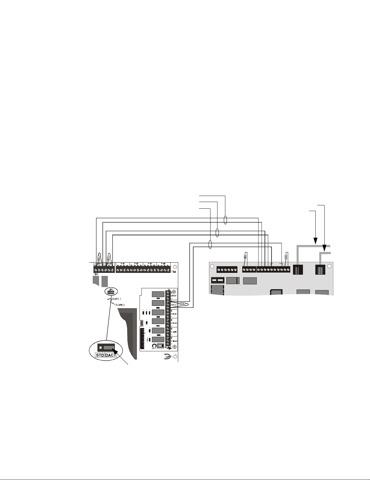
Universal Digital Alarm Communicator - 411UDAC Appendix C: NFPA Standard-Specific Requirements
Universal Digital Alarm Communicator - 411UDAC
The following figure illustrates an example of Central Station/Remote Station Receiver or Protected
Premises Receiving Unit reporting using a 411UDAC. The relay contacts of the PDRP-1002 may be used
to trip any dialer listed for Central Station/Remote Station services. For additional information refer to the
Instruction Manual for the 411UDAC.
• All connections between the control panel and the 411UDAC must be in conduit, less than 20 feet
(6.1 meters) in length in the same room.
• The PDRP-1002 is non suitable for transmission of a supervisory signal to the DACT.
• Any zone of the 411UDAC can be wired to function as alarm or trouble; the unit must be
programmed accordingly. In this example, Zone 1 is wired to the control panel’s alarm relay, Zone2
is wired to the control panel’s trouble relay, and Zone 3 is wired to the optional module’s supervisory
relay.
• AC power is supplied directly to the 411UDAC, not through the control panel. AC wiring for both
the 411UDAC and the control panel must be connected to the same AC branch circuit.
• End-of-Line Resistors must terminate all circuits. In this example, Zone 4 is unused and is
terminated at the board.
• When employing a DACT, place the JP1 jumper, on the control panel, as shown below. This directs
the panel to transmit all trouble conditions except AC LOSS. The DACT must be configured to
transmit AC power loss to the central station.
Alarm
Trouble
Jumper
Control Panel
Figure 25 411UDAC Connections
Zone 1
Zone 2
Zone 3
Supervisory
4XZM Zone
Relay Module
RELAY 1
NO NC C
RELAY 2
NO NC C
TB1
NAC
B+ B-
Secondary Phone Line
Primary Phone Line
ZONE 1
ZONE 2
B+ B-
B+ B-
ZO NE 3
B+ A+ A- B-
+12V PWR
+ -
TB4
411 UDAC
ZONE 4
B+ B-
TB2
PH1
PH2
Modular Cable
P/N MCBL-6
MS44-411.cdr
PDRP-1002 Instruction Manual PN 51135:B0 04/06/01
49
Page 50
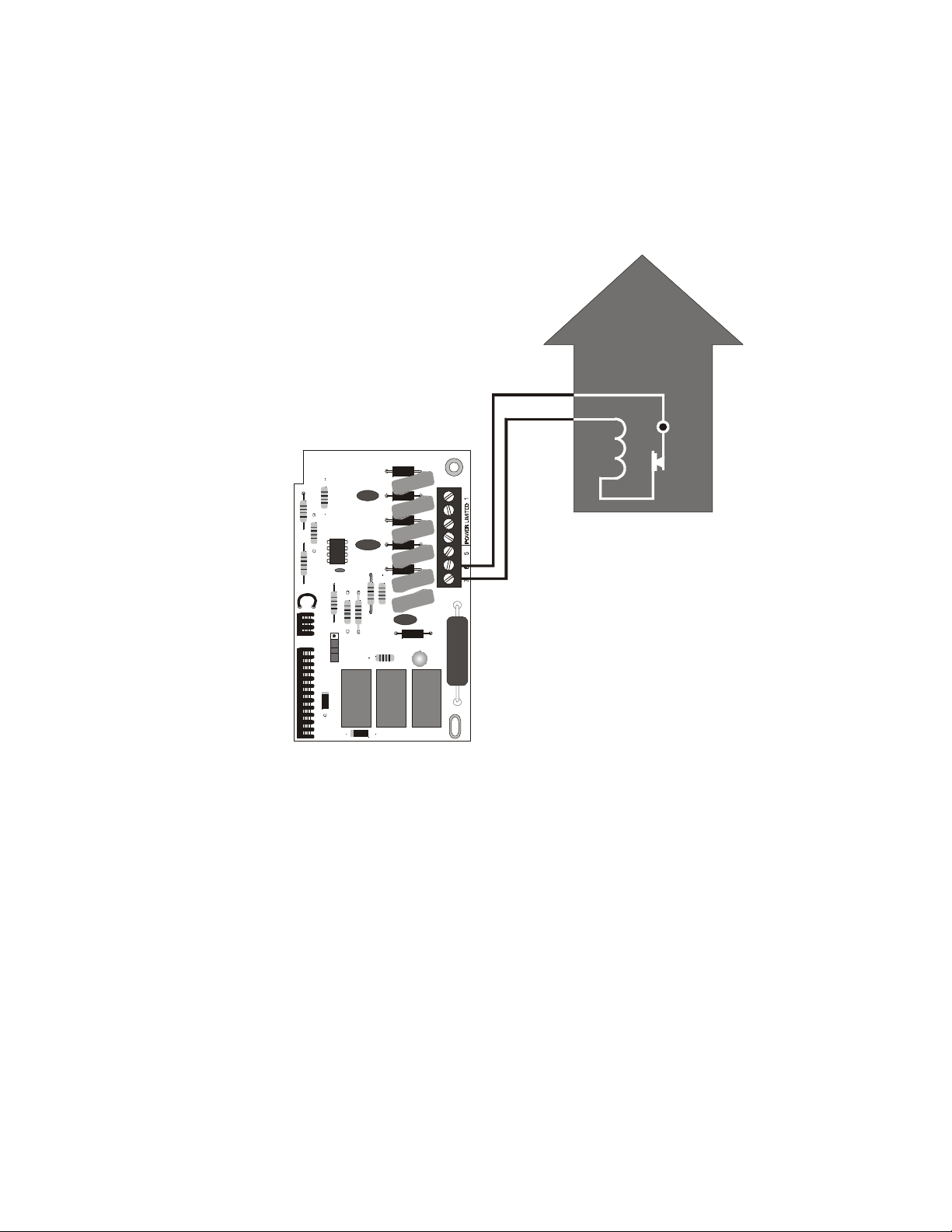
Appendix C: NFPA Standard-Specific Requirements Local Energy Municipal Box
Local Energy Municipal Box
Using the 4XTM Transmitter Module for connection to a Local Energy Municipal Box.
• The Municipal Box circuit supervises for ground faults and opens (i.e. missing wire) but not for
direct short between two wires. It is not a power-limited circuit.
• This application is not suitable for separate transmission of sprinkler supervisory or trouble
conditions.
• Maximum loop resistance allowed for wiring from control panel to Municipal Box is 3 ohms.
FIRE
TBL
Municipal Box Circuit
+
–
TB1
Local Energy
Municipal Box
J1
J2
4XTM Transmitter Module
(activated polarities shown)
Figure 26 Municipal Box Connection
MS44-4xtmfmb.cdr
50
PDRP-1002 Instruction Manual PN 51135:B0 04/06/01
Page 51
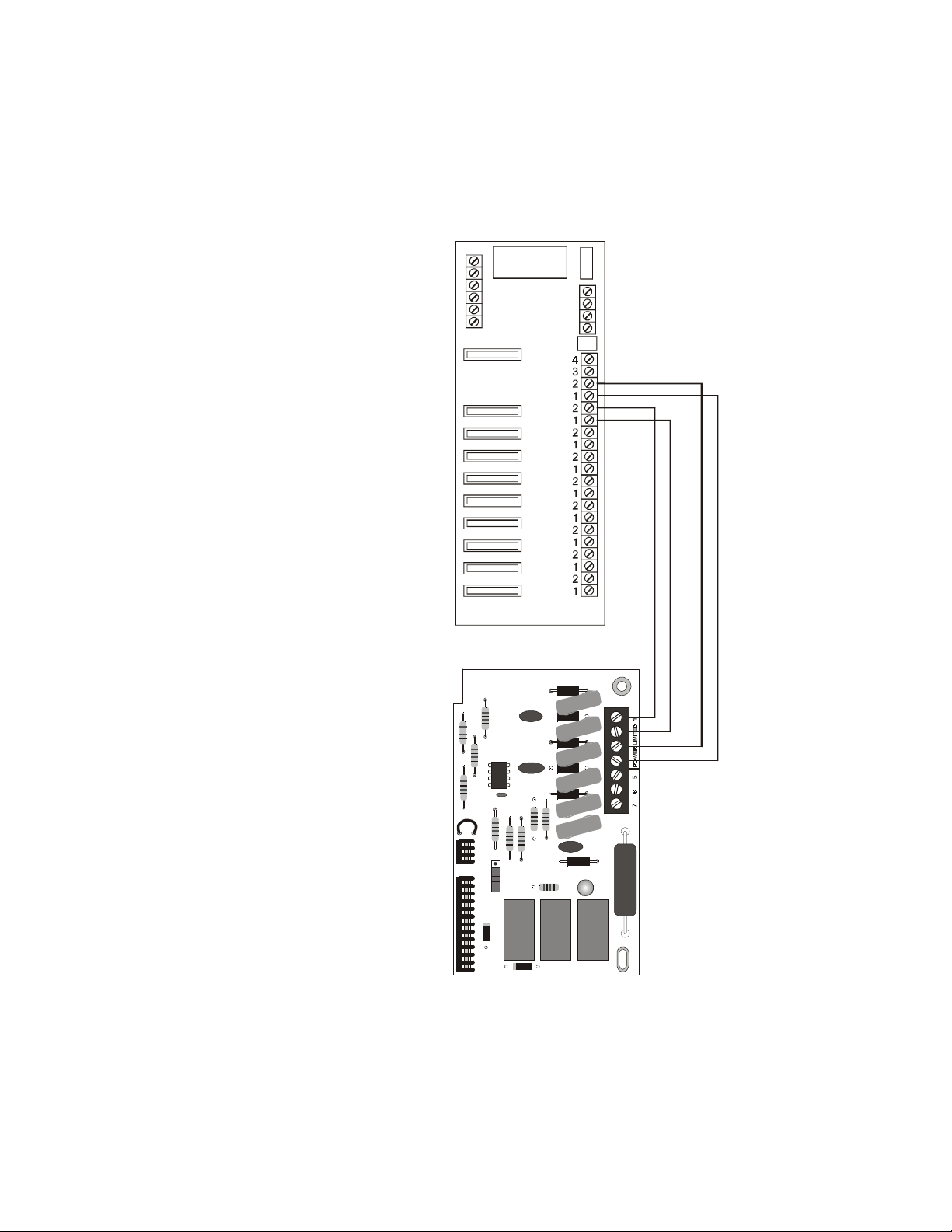
Remote Station Receiver - RS82-9 Appendix C: NFPA Standard-Specific Requirements
Remote Station Receiver - RS82-9
Using the 4XTM Transmitter Module for connection to a Fire•Lite RS82-9 Remote Station Receiver.
• Intended for connection to a polarity reversal circuit of a remote station receiving unit having
compatible ratings.
• All connections are power-limited and supervised with the exception of the reverse polarity loop.
• Supervision of the loop is the responsibility of the receiver.
Fire•Lite RS82-9
Remote Station
Receiver
4XTM Transmitter
Module
Figure 27 RS82-9 Connections
+ –
+ –
Remote
Alarm
TB1
Remote
Trouble
TBL
J1
J2
MS44-rs82.cdr
PDRP-1002 Instruction Manual PN 51135:B0 04/06/01
51
Page 52

Appendix C: NFPA Standard-Specific Requirements Remote Station Receiver - RS82-9
Notes
52
PDRP-1002 Instruction Manual PN 51135:B0 04/06/01
Page 53

Testing
Appendix D: Testing & Maintenance
Inspection
Perform the following prior to applying power to the system.
• Check the actual wiring hookup with the wiring diagrams.
• Insure that no pieces of wire have fallen into the circuitry.
• Check for missing or damaged parts.
Alarm Test
An initial alarm test should be conducted following installation to determine that all parts of the system
are functioning properly. The panels should remain powered for 24 to 36 hours proir to connecting the
releasing solenoids. This precaution will avoid false discharges of gas in case of faulty or improperly placed
detectors.
To perform an alarm test on the panel follow this procedure
1. Disconnect AC power and battery power.
2. Disconnect the installed solenoid valve circuit leads an connect spare solenoid valves, or connect
an end-of-line device to serve as a dummy load.
3. Reconnect AC power and battery power.
4. Initiate a first zone alarm condition by blowing smoke into one of the Zone 1 smoke detectors. This
should cause the first zone alarm condition.
• The alarm relay will energize.
• The red zone alarm LED will be illuminated.
• The remote Indicating Circuit #1 audible alarm and the local piezo will start sounding.
Maintenance
A regular schedule of inspection, testing, and maintenance is vital to insure proper and reliable operation
of the control panel. The procedures should be performed as required by the local authority having
jurisdiction. Refer to NFPA for further details.
Troubleshooting
A troubleshooting table is included on the following page which provides for symptoms, problems and
their solutions.
PDRP-1002 Instruction Manual PN 51135:B0 04/06/01
53
Page 54

Appendix D: Testing & Maintenance Troubleshooting
Table 9 Troubleshooting Table
Symptom Problem Solution
1. Check TB2 for proper connections.
2. Remove all field wiring and install dummy ELR at
output circuit. Check for supervisory voltage across it,
(Normal -2.3 V), if problem persists, replace circuit
board.
3. Removed dummy ELR, reconnect field wiring and
measure voltage across output; (trouble-5V, short 0V).
4. Check for ELR at last device.
5. Check field wiring.
1. Check TB4 for proper connections.
2. Remove field wiring for zone in trouble and install
dummy ELR (4.7K). If problem persists, replace
circuit board.
3. Check for ELR at last device.
4. Check field wiring.
1. Check installation manual.
1. Check battery connections.
1. Remove batteries, check voltage across charger
output (17 to 19V), otherwise replace circuit board.
2. Reconnect batteries, measure battery voltage at
battery terminals. If voltage is less than 85% of rated
voltage, allow them to charge for 48 hours.
3. If problem persists, replace batteries.
1. Remove field wiring from main panel and optional
module(s) (if installed). Install dummy ELR (4.7K).
2. Remove both battery leads.
3. If trouble clears, connect one circuit at the time to
pin point the problem.
4. If trouble doesn’t clear, replace circuit board.
1. Move Municipal Box disconnect switch SW1 up.
1. Install optional module(s) or replace jumper if
module(s) is not used.
1. Install dummy load if Municipal Box option isn’t
used.
2. Check Municipal Box wiring.
1. Remove field wiring and install ELR. If trouble
clears, look for faulty or incorrectly wired devices.
1. Cut associated jumper OPT1 or OPT2.
1. Make sure module is properly installed.
2. Move disable switch SW1 on 4XZM to the left.
1. Make sure that 4XLM module is installed on J8.
2. Check field wiring.
1. Replace circuit board.
1. Press system reset.
1. Check incoming power (TB5).
1. Replace circuit board.
1. Replace circuit board.
AC
Power
LED ON
AC
Power
LED OFF
Circuit trouble
LED ON
Any of the right
column yellow
LEDs flashing
Notification appliance circuit
trouble
Initiating zone open circuit
trouble
Any of the right
System trouble
LED ON
column yellow
LEDs steady
ON
Zone disable
Missing or
Disconnected
Battery trouble
Batt yellow
LED ON
Power trouble
Low or
damaged
battery
LED ON
Ground fault trouble
Earth yellow LED ON
Yellow LED on
4XTM ON
4XTM
OPT1, OPT2 jumper cut
Municipal Box open circuit
Any of the right column red LEDs
ON
Disconnecting Municipal Box
switch ON 4XTM does not create
a trouble
Short on initiating circuit wiring
Jumper for optional modules
isn’t cut
4XZM: associated LED doesn’t
activate for alarm, trouble or
Optional module trouble
supervisory conditions
RZA-4X piezo doesn’t sound for
alarm, trouble or supervisory
4XLM
conditions
Micro Fail yellow LED ON Microprocessor damaged
All RZA-4X LEDs stay ON
System trouble LED ON
Power wasn’t removed prior to
installation
Loss of main power
Damaged circuit breaker
Micro Fail yellow LED ON Microprocessor damaged
54
PDRP-1002 Instruction Manual PN 51135:B0 04/06/01
Page 55

Index
Index
Numerics
110/120 VAC 12
220/240 VAC 12
411UDAC 47, 49
4XLM LED Interface Module 11, 23
4XMM Meter Module 11, 15
4XTM Transmitter Module 10, 23, 47
4XTMF Transmitter Module 50, 51
4XZM Zone Relay Module 10, 23
4XZMF Zone Relay Module 30
911AC DACT 47, 48
A
Abort Function 29
Abort Switch Circuit 18
Abort timer 29
AC branch circuit 49
AC power 33, 49, 53
accidential discharge 21
acknowledge 34
activation 29
additional equipment 47
alarm 33, 49
Alarm Relay 37
alarm relay 22, 53
allowable resistance 19
ammeter 11
annunciator wiring 11
audible alarm 53
authority having jurisdiction 53
B
backbox 13
backbox rail 13, 14
Batteries 16, 47
battery
cable 17
capacity 40
charger 40
interconnect wire 16, 17
power 53
BB-17 12, 40
black wire 17
Brownout circuitry 37
buffer 36
C
Canadian 28, 35, 36
Central Station 47, 48, 49
charging current 15
circuit
Remote Alarm 25
Remote Trouble 25
reverse polarity 10
circuit board 13
circuit breaker 16
CO2 releasing applications 33
conductors 13
conduit 13, 49
configuration, Zone Relay Module 30
Cross Zone 28, 37
current 12, 21
current draw 37
D
DC power connections 22
de-energize 37
delay timers 29
detector, four-wire smoke 34
detectors, type of 18
devices 21
devices, supplementary 22
dialer 47, 49
DIP switch 20, 26, 28, 35
DIP Switch #1 28, 30
DIP Switch #2 29, 30
DIP Switch #3 & #4 29
DIP Switch #5 & #6 29
DIP switch functions 10
direct short 50
disable switch 26
disabled zone 35
discharge, accidential 21
Disconnect LED 25
Disconnect Switch 25
dry contacts 26
dummy load 20, 21
dummy load resistor 18
duplicate modules 23
E
earth fault 33
ELR 19, 20
End-of-Line Resistor 12, 49
energize 37
event 33
exterior dimensions 14
external battery cabinet 12
external devices 12
F
Fire Alarm Control Panel 47
first alarm 37
first zone 53
FM approved 47, 48
Form-C contacts 10, 12
four-wire smoke detector 12, 34
PDRP-1002 Instruction Manual PN 51135:B0 04/06/01
55
Page 56

Index
G
General Alarm 30
ground fault 33, 50
I
Indicating Circuit #1 53
initial alarm test 53
initiating circuits 34
initiating device 37, 47
Initiating Device Circuit 36
inspection 53
interconnect wire, battery 31
Interface Module 11
interruption of circuits 36
IRI-type delay timer 29
J
J1 connector 13, 14
J2 Connector 15
J3 Connector 15
J9 Connector 17
JP1 jumper 49
jumper 23, 24
LATCH 26
Meter Module 11, 15
microprocessor 33
minimum clearance 13
minimum voltage 21
module connectors 23
motherboard 33
mounting hole locations 14
mounting holes 13
Municipal Box 25, 50
N
NACs 20
National Electrical Code, Article 760 16
National Fire Protection Association 47
negative 17
NFPA 53
NFPA standards 47
non-latching 26, 34
nonpower-limited 17, 21, 26
nonresettable power 19, 22
non-silenceable service 20
Notification Appliance Circuit 34
Notification Appliances 47
NYC-type delay timer 29
K
keyhole 13
knockouts 13, 17
L
label
Protected Premises Unit 26
terminal identification 23, 24
LAMP TEST function 34
latch 34, 35
LATCH jumper 26
latching operation 35, 36
LED
Disconnect 25
System Trouble 25
LED Interface Module 11, 23
LEDs
Alarm, Trouble and Supervisory 33
Local Energy Municipal Box 10
Local Jurisdiction delay timer 29
loop resistance 50
lower position 23, 24
M
main breaker panel 16
maintenance 53
Manual Pull Stations 18
Manual Release Circuit 18
manual station 37
maximum allowable resistance 21
Maximum Battery Capacity 12
Maximum Charging Circuit 12
maximum resistance 19
O
opens 50
operating mode 28
operating voltage 19
optional boards 34
optional modules 10
Out of Service 31
output circuits 34
overcurrent protection 16
P
paper labels 11
physical lockout 33
piezo 34, 35, 36, 37, 53
piezo tones 34
polarity 17, 18, 31
polarity reversal circuit 51
polarized devices 18, 20
positive 17
power connection 16
Power Supervision Relay 19
power-limited 17, 20, 21, 26, 51
power-limited power supply 22
predischarge timer 37
previous panel status 36
primary power 16, 31
programmed 49
Protected Premises Receiving Unit 47, 48, 49
protected space 33
56
PDRP-1002 Instruction Manual PN 51135:B0 04/06/01
Page 57

Index
R
rail 24
rail, backbox 13, 14
red wire 17
regulated power 22
relay contacts 49
Relay, System Alarm 34
release 33
releasing 21
Releasing Circuit 20, 21
Releasing Circuit #2 29
Releasing Devices 47
Remote Alarm circuit 25
Remote Annunciator 11
Remote Station 47, 49
Remote Station Service 10
Remote Trouble circuit 25
reset switch 37
resettable power 19, 22
resistance, allowable 19
resistor 49
resound 34
reverse polarity 25
reverse polarity circuit 10
reverse polarity loop 51
RS82-9 Remote Station Receiver 47, 51
RZA-4X Remote Annunciator 11
S
second alarm 37
Secondary Power 31
secondary power source 39
self-restoring 34
separate transmission 50
short circuit 35
silence switch 11
Slide-in paper labels 11
solenoid valve 37, 53
sprinkler 35, 36
sprinkler supervisory 50
Standard UL-type delay timer 29
Standby Battery Current 39
stand-off 14, 23, 24
Style B (Class B) 18
Style D (Class A) 18
Style Y (Class B) 20, 21
Style Z (Class A) 20
sulfuric acid 31
supervised 20
Supervisory Circuit 21
supervisory device 33, 35
supervisory signal 49
Supervisory/Releasing Service 29
supplementary devices 22
suppresant agent 37
switch, disable 26
System Alarm Relay 34
System Trouble 30
System Trouble LED 25
T
tag, “Out of Service” 31
terminal identification label 23, 24
testing 53
Timer Delay 29
timer, pre-discharge 37
timer, watchdog 33
tone patterns 35
tones, piezo 34
tracking operation 35, 36
transformer wires 13, 14
Transmitter Module 10, 23, 50, 51
trim ring 14
trouble 49
condition 33, 36, 50
relay 22
trouble sounder 11
troubleshooting 53
U
UL listed 47
UL Standard 864 29
unused circuits 20, 21
upper position 23
V
visual inspection 31
voltage 15
voltage drop 12
voltmeter 11
W
watchdog timer 33
Waterflow 18
wire, primary power 16
wires, transformer 13
Z
zone 49
Zone Relay Module 10, 23
PDRP-1002 Instruction Manual PN 51135:B0 04/06/01
57
Page 58

58
PDRP-1002 Instruction Manual PN 51135:B0 04/06/01
Page 59

PDRP-1002 Instruction Manual PN 51135:B0 04/06/01
59
Page 60

Limited Warranty
System Sensor
®
warrants its products to be free from defects in materials and workmanship for eighteen (18) months from the date of manufacture, under normal use and service. Products are date stamped at time of manufacture. The sole and exclusive
obligation of System Sensor
®
is to repair or replace, at is option, free of charge for parts
and labor, any part which is defective in materials or workmanship under normal use and
®
service. For products not under System Sensor
warranty is eighteen (18) months from date of original purchase by System Sensor
manufacturing date-stamp control, the
®
distributor unless the installation instructions or catalog sets forth a shorter period, in which
case the shorter period shall apply. This warranty is void if the product is altered, repaired
®
or serviced by anyone other than System Sensor
or its authorized distributors or if there
is a failure to maintain the products and systems in which they operate in proper and workable manner. In case of defect, secure a Return Authorization Number from our Customer
Service Department. Return product, transportation prepaid, to System Sensor Repair
Department, RA #_____, 3825 Ohio Avenue, St. Charles, IL 60174. Please include a note
describing the malfunction and suspected cause of failure.
This writing constitutes the only warranty made by System Sensor
®
products. System Sensor
does not represent that its products will prevent any loss by
®
with respect to its
fire or otherwise, or that its products will in all cases provide the protection for which they
are installed or intended. Buyer acknowledges that System Sensor
®
is not an insurer and
assumes no risk for loss or damages or the cost of any inconvenience, transportation,
damage, misuse, abuse, accident or similar incident.
SYSTEM SENSOR
®
GIVES NO WARRANTY, EXPRESSED OR IMPLIED, OF MERCHANTABILITY, FITNESS FOR ANY PARTICULAR PURPOSE, OR OTHERWISE
WHICH EXTEND BEYOND THE DESCRIPTION ON THE FACE HEREOF. UNDER NO
®
CIRCUMSTANCES SHALL SYSTEM SENSOR
BE LIABLE FOR ANY LOSS OF OR
DAMAGE TO PROPERTY, DIRECT, INCIDENTAL OR CONSEQUENTIAL, ARISING
OUT OF THE USE OF, OR INABILITY TO USE SYSTEM SENSOR
®
THERMORE, SYSTEM SENSOR
SHALL NOT BE LIABLE FOR ANY PERSONAL
®
PRODUCTS. FUR-
INJURY OR DEATH WHICH MAY ARISE IN THE COURSE OF, OR AS A RESULT OF,
PERSONAL, COMMERCIAL OR INDUSTRIAL USE OF ITS PRODUCTS.
This warranty replaces all previous warranties and is the only warranty made by System
Sensor
®
. No increase or alteration, written or verbal, of the obligation of this warranty is
authorized.
3825 Ohio Avenue
St. Charles, IL 60174
1-800-SENSOR2
Fax: (630) 377-6495
 Loading...