

Page 1
System Sensor
3825 Ohio Avenue
St. Charles, IL 60174
1-800-SENSOR2
Fax: 630-377-6495
PDRP1002.CD
The PDRP-1002/PDRP-1002E
Agent Release Control System
Manual
Document 51135
I56-1358-00
03/11/99 Revision:
PN 51135:A ECN 99-017
A
Page 2

Installation Precautions
g
d
u
n
s
e
t
d
s
o
I
o
n
o
b
o
s
– Adherence to the following will aid in problem-free installation with long-term reliability:
WARNING
fire alarm control panel. Disconnect all sources of power before
servicing. Control unit and associated equipment may be damaged by
removing and/or inserting cards, modules, or interconnecting cables
while the unit is energized. Do not attempt to install, service, or operate
this unit until this manual is read and understood.
CAUTION
ensure proper system operation, this product must be tested in
accordance with NFPA 72-1993 Chapter 7 after any programming
operation or change in site-specific software. Reacceptance testing is
required after any change, addition or deletion of system components, or
after any modification, repair or adjustment to system hardware or
wiring.
All components, circuits, system operations or software functions known
to be affected by a change must be 100% tested. In addition, to ensure
that other operations are not inadvertently affected, at least 10% of
initiating devices that are not directly affected by the change, up to a
maximum of 50 devices must also be tested and proper system
operation verified.
This system
32-120
30
and the electronic components may be adversely affected by extreme
temperature ranges and humidity. Therefore, it is recommended that this
system and its peripherals be installed in an environment with a nominal
room temperature of 15-27
Verify that wire sizes are adequate
devices cannot tolerate more than a 10% I.R. drop from the specified
device voltage.
- Sever al different sources of power can be connected to the
- System Reacceptance Test after Software Changes: To
O
meets NFPA requirements for operation at 0-49
O
F and at a relative humidity of 85% RH (non-condensing) at
O
C/86O F. However, the useful life of the system's standby batteries
O
C/60-80O F.
for all initiating device loops. Most
C/
Fire Alarm System Limitati on s
An automatic fire alarm system
detectors, heat detectors, manual pull stations, audible warning devices
and a fire alarm control with remote notification capability can provide
early warning of a developing fire. Such a system, howev er, does not
assure protection against property damage or loss of life resulting from a
fire.
Any fire alarm system may fail for a variety of reasons:
Smoke detectors
detectors such as in chimneys, in walls, or roofs, or on the other side of
closed doors. Smoke detectors also may not sense a fire on another
level or floor of a building. A second floor detector , for example, may not
sense a first floor or basement fire. Furthermore, all types of smoke
detectors - both ionization and photoelectric types, have sensing
limitations. No type of smoke detector can sense every kind of fire
caused by carelessness and safety hazards like smoking in bed, violent
explosions, escaping gas, improper storage of flammable materials,
overloaded electrical circuits, children playing with matches, or arson.
IMPORTANT!
the control panel and in rooms used by the system for the connection of
alarm transmission wiring, communications, signaling and /or power. If
detectors are not so located, a developing fire may damage the alarm
system, crippling its ability to report a fire.
may not sense fire where smoke cannot reach the
Smoke detectors must be installed in the same room as
- typically made up of smoke
FCC Warning
Like all solid state electronic devices
erratically or can be damaged when subjected to lightning induced
transients. Although no system is completely immune from lightnin
transients and interferences, proper grounding will reduce
susceptibility. Overhead or outside aerial wiring is not recommende
due to an increased susceptibility to nearby lightning strikes. Cons
with the Technical Services Department if any problems are
anticipated or encountered.
Disconnect AC power and batteries
circuit boards. Failure to do so can damage circuits.
Remove all electronic assemblies
or punching of the enclosure. When possible, make all cable entrie
from the sides or rear. Before making modifications, verify that they
will not interfere with battery, transformer and printed circuit board
location.
Do not tighten screw terminals
may damage threads, resulting in reduced terminal contact pressur
and difficulty with screw terminal removal.
This system
yourself with a proper wrist strap before handling any circuits so tha
static charges are removed from the body. Use static suppressive
packaging to protect electronic assemblies removed from the unit.
Follow the instructions
programming manuals. These instructions must be followed to avoi
damage to the control panel and associated equipment. FACP
operation and reliability depend upon proper installation.
While installing a fire alarm system may make lower insurance
rates possible, it is not a substitute for fire insurance!
Audible warning devices
devices are located on the other side of closed or partly open doors
are located on another floor of a building.
A fire alarm system will
AC power f ails, the system will operate from standby batteries only f
a specified time.
Rate-of-Rise heat detectors
over time. For this reason, the rate-of-rise feature of each detector
should be tested at least once per year by a qualified fire protection
specialist.
Equipment used in the system
with the control panel. It is essential to use only equipment listed fo
service with your control panel.
T
elephone lines
central monitoring station may be out of service or temporarily
disabled.
The most common cause
inadequate maintenance. All devices and system wiring should be
tested and maintained by professional fire alarm installers following
written procedures supplied with each device. System inspection a
testing should be scheduled monthly or as required by National and/
local fire codes. Adequate written records of all inspections should
kept.
contains static-sensitive components Always ground
in the installation, operating and
such as bells may not alert people if the
not operate without any electrical power.
may be subject to reduced sensitivity
needed to transmit alarm signals from a premise to
of fire alarm malfunctions, however, is
, this system may operate
prior to removing or inserting
prior to any drilling, filing, reami
more than 9 in-lbs. Over tightenin
may not be technically compatible
WARNING:
frequency energy and if not installed and used in accordance with the
instruction manual, may cause interference to radio communications, It
has been tested and found to comply with the limits for class A
computing device pursuant to Subpart B of 15 of FCC Rules, which is
designed to provide reasonable protection against such interference
when operated in a commercial environment. Operation of this
equipment in a residential area is likely to cause interference, in which
case the user will be required to correct the interference at his own
expense.
This equipment generates, uses and can radiate radio
2 The PDRP-1002 PN 51135:A 03/11 / 99
Canadian Requirements
This digital apparatus does not exceed the Class A limits for radiati
noise emissions from digital apparatus set out in the Radio
Interference Regulations of the Canadian Department of
Communications.
Le present appareil numerique n'emet pas de bruits radioelectrique
depassant les limites applicables aux appareils numeriques de la
classe A prescrites dans le Reglement sur le brouillage
radioelectrique edicte par le ministere des Communications du
Canada.
Page 3

The PDRP-1002 PN 51135: A 03/11/99 3
Page 4

4 The PDRP-1002 PN 51135:A 03/11 / 99
Page 5

NFPA Standards
This control panel complies with the following NFPA standards:
NFPA 12 CO
NFPA 12A Halon 1301 Extinguishing Systems
NFPA 12B Halon 1211 Extinguishing Systems
NFPA 72 Central Statio n Signaling Systems (Automatic, M a nual, and Waterflow). Protected
Premises Unit (Requires NOTI•FIRE 911AC DACT or MS-5012 Slave Communicat or)*
NFPA 72 Local (Automatic, Manual, Waterflow and Sprinkler Supervisory) Fire Alarm Systems
NFPA 72 Auxiliary (Automatic, Manual, and Waterflow) Fire Alarm Systems. (Requires 4XTM)
NFPA 72 Remote Station (Automatic, Manual, and Waterflow) Fire Alarm Systems. Requires
4XTM, NOTI•FIRE 911AC DACT*
NFPA 2001 Clean Agent Fire Extinguish in g Sys te m s
*Applications which require the NOTI•FIRE 911AC are not FM approved.
Additional Information
Before proceeding, the installer should be familiar with the following documents and
standards:
NFPA Standards:
NFPA 12 CO2 Fire Extinguishing Systems
NFPA 12A Halon 1301 Fire Ext inguishing Systems
NFPA 12B Halon 1211 Fire Extinguishing Systems
NFPA 72 Installation, Maintenance and Use of Central Station Signaling Systems
NFPA 72 Local, Auxiliary, Remote Station and Proprietary Fire Alarm Systems
NFPA 72 Automatic Fire Detectors
NFPA 72 Installation, Maintenance and Use of Notification Appliances for Fire Alarm Systems
NFPA 72 Testing Procedures for Signaling Systems
NFPA 2001 Clean Agent Fire Extinguish in g Sys te m s
Extinguishing Systems (High Pressure Only)
2
Underwriters Laboratories Documents:
UL 38 Manual Actuated Signaling Boxes
UL 217 Smoke Detectors, Single and Multiple Station
UL 228 Door Closers - Holders for Fire Alarm Systems
UL 268 Smoke Detectors for Fire Alarm Systems
UL 268A Smoke De te c t o r s for D uc t Ap plications
UL 346 Waterflow Indicators for Fire Alarm systems
UL 464 Audible Signaling Appliances
UL 521 Heat Detectors for Fire Alarm Systems
UL 864 Standard for Control Units for Fire Alarm Systems
UL 1481 Power Supplies for Fire Alarm Systems
UL 1638 Visual Signaling Appliances
UL 1971 Signaling Devices for the Hearing Impaired
CAN/ULC-S524-M91 Standard for Installation of Fire Alarm Systems
CAN/ULC-S527-M87 Standard for Control Units for Fire Alarm Systems
Other:
NEC Article 300 Wiring Methods
NEC Article 760 Fire Alarm Systems
Applicable Local and State Building Codes
Requirements of the Local Authority Having Jurisdiction
Notifier Device Compatibility Document, 15378
ADA Americans with Disabilities Act
The PDRP-1002 PN 51135: A 03/11/99 5
Page 6

1 The PDRP-1002/PDRP-1002E
1 The PDRP-1002/PDRP-1002E
Features
• Microprocessor-controlled
• Power-limited on all circuits except Municipal Box output
• Alarm and trouble resound
• Four Class A (Style D)/Class B (Style B) Initiating Device Circuits
• Two Class A (Style Z)/Class B (Style Y) Notification Appliance circuits
• Two Class B (Style Y) Release Circuits
• General alarm and trouble relays
• Optional module for 4 zone/function relays (4XZM)
• Optional transmitter module (4XTM). Complies with NFPA 72 Auxiliary and
Remote Station Fire Alarm systems
• Optional volt/amp meter module (4XMM)
• Optional supervised remote annunciator (RZA-4X)
• Requires LED Interface Module (4XLM)
• Optional digital communicator (NOTI•FIRE 911AC)*
• Complies with NFPA 72 Central Station and Remote Station Fire Alarm Systems
• Supervisory Input Option
• Delay timer (adjustable)
• Three abort function options
• Designed for suppression standards NFPA 12, 12A and 12B
• Disable/enable controls per initiating zone
• Last Event Recall
• Battery/Earth fault supervision
• Fuse protection on all Notification/Release Circuits
• RMS regulated output power, 2.25 amps
• 7 amp/hour to 15 amp/hour battery options, up to 90 hours standby
• Resettable and non-resettable regulated power outputs
• Extensive transient protection
• Watchdog timer to supervise microprocessor
• Output circuits protected against false activations
• Slide-in zone identification labels
• Steel cabinet 14.5 in (368.3 mm) wid e b y 16 i n ( 406. 4 mm) high b y 5 in (127 m m)
deep
• Dead-front dress panel option (DP-4X)
• Trim ring for flush mount between 16 in (406.4 mm) center studs (TR-4XR)
• Abort and manual release circuits
• Cross-zone option
Input Circuits
Applications which require the NOTI•FIRE 911AC are not FM approved
*
.
Circuits
Input Circuits
Detector Zone 1, Class A (Style D)/Class B (Style B)
Detector Zone 2, Class A (Style D)/Class B (Style B)
Abort, Class A (Style D)/Class B (Style B)
Manual Release, Class A (Style D)/Class B (Style B)
Output circuits (optional auxiliary relays track these four circuits)
Notification Appliance Circuit 1, Class A(Style Z)/Class B (Style Y)
Notification appliance Circuit 2, Class A(Style Z)/Class B (Style Y)
Releasing Circuit 1, Class B (Style Y)
Releasing Circuit 2, Class B (Style Y)/Supervis ory Input, Class B (Style B)
6 The PDRP-1002 PN 51135:A 03/11 / 99
Page 7
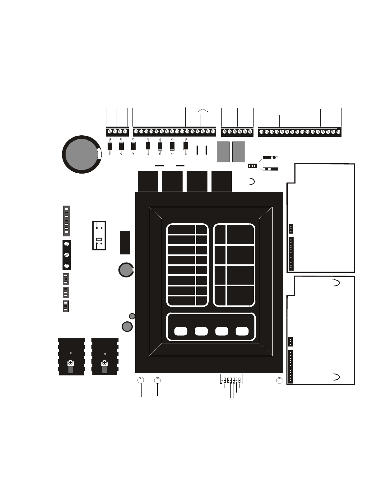
Front Panel Control Switches
1 The PDRP-1002/PDRP-1002E
Front Panel Control Switches
Switch 1 Tone Silence
Switch 2 Alarm Silence
Switch 3 Alarm Activate
Switch 4 System Reset
Ground
Neutral
Hot
Transformer
J1
TB5
J2
Optional Ammeter
Connection
J9
Batteries
+
Optional
J3
VoltmeterConnection
+24VU
+ -
+ -
TB1
AC Circuit Breaker
24 VVU
RMS-REGULATED
24 VR
+24VR
Notification Appliance
Circuits
Class A (Style Z)
Class B (Style Y)
1234
24 VNR
REGULATED
REGULATED
NON-RESETTABLE
RESETTABLE
+24VNR
B+ A+ A- B-
+ -
B+ A+ A- B-
Releasing
Circuits
B+ B-
B+ B-
Relays
TroubleAlarm
Contacts Contacts
NO NC C NO NC C
Initiating Device
Circuits
Class A (Style D)
Class B (Style B)
Abort
Switch
Manual
Release
1234
B+ A+ A- B-
B+ A+ A- B-
B+ A+ A- B-B+ A+ A- B-
TB4
TB2
TB3
JP 1
NO DACT
DACT
SUPV 2
4XTM
GEN ALM2
or
4XLM
or
4XZM
*Jumper “OPT 1” must
be cut if a module is
installed in this position
OPT 1
*
4XTM
or
4XLM
or
4XZM
*Jumper “OPT 2” must
be cut if a module is
installed in this position
O
123456
Cross Zone
Supervisory
Delay Timer
N
SW1
Abort Option
Abort Option
Delay Timer
Micro Fail LED
BATT
EARTH
Ground Fault LEDBattery Fail LED
Figure 1 PDRP-1002/P DRP-1002E Installatio n Di agram
The PDRP-1002 PN 51135: A 03/11/99 7
OPT 2
*
4XRP1002.cdr
Page 8
1 The PDRP-1002/PDRP-1002E
4XTM.cdr
4XLM.cdr
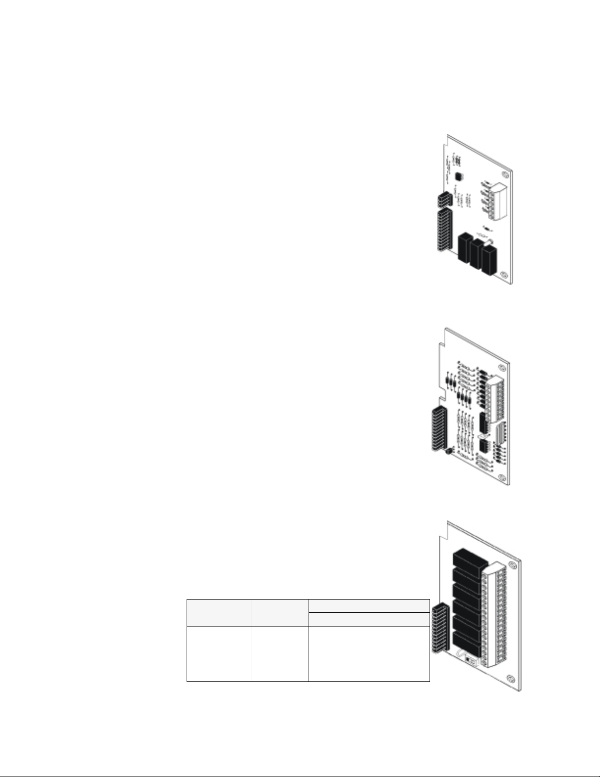
Optional Boards
The PDRP-1002/PDRP-1002E has mounting slots for two option boards. Any two of
the three option modules may be installed.
Transmitter Module (4XTM - NOTIFIER)
The Transmitter Module provides a supervised output for
local energy municipal box transmitter (for NFPA 72
Auxiliary Fire Alarm System) and alarm and trouble
reverse polarity circuits (for NFPA 72 Remote Statio n Fi re
Alarm System). Also included is a DISABLE switch and
disable trouble LED.
As a jumper option, the alarm reverse polarity circuit will
open on trouble if no alarm exists.
LED Interface Module (4XLM - NOTIFIER)
The LED Interface Module supports the RZA-4X Remote
Annunciator module. Annu nciator wi ring is superv ised for
open conditions by this module. The Annunciator Driver
Module mounts to the main board, occupying on e of the
two option connectors.
Transmitter Module (4XTM - NOTIFIER)
Zone Relay Module (4XZM - NOTIFIER)
The Zone Relay module provides Form-C contacts for the
following:
As a jumper option, the first four relays described below can
be made silenceable.
DIP 1=OFF
Either Zone
Alarm Detected First Alarm Alarm Detected First Alarm
Alarm Detected Second Alarm Alarm Detected Second Alarm
Release 1 Release 1 Release Release
Release 2 Release 2 Not Used Not Used
8 The PDRP-1002 PN 51135:A 03/11 / 99
DIP 1=ON
Cross Zone
If Supervisory (DIP 2=ON)
Either Zone Cross Zone
4XZM.cdr
Page 9
Transmitter Module (4XTM - NOTIFIER)
RZA4Xfr.cdr
voltmter.cdr
Transmitter Module (4XTM - NOTIFIER)
For Local Energy Municipal Box service (NFPA 72 Auxiliary Fire Alarm System)
Supervisory current: 5.0 mA
Trip current: 0.35 amps. (Subtracted from Notification Appliance power)
Coil Voltage: 3.65 VDC
Coil resistance: 14.6 ohms
Maximum allowable wire resistance between panel and trip coil: 3 ohms
Municipal Box wiring can leave the building
For Remote Station service (NFPA 72 Remote Station Fire Alarm
System):
Maximum load for each circuit: 10mA
Reverse polarity output voltage: 24 VDC
Remote Alarm and Remote Trouble wiring can leave the b uilding
LED Interface Module (4XLM - NOTIFIER)
Maximum voltage/current, each output: 27.6V/8mA
Note: Outputs are power limited
Zone Relay Module (4XZM - NOTIFIER)
Dry Form-C contacts rated: 2.0 amps @ 30VDC (resistive), 0.5 amps @ 30 VAC
(resistive)
1 The PDRP-1002/PDRP-1002E
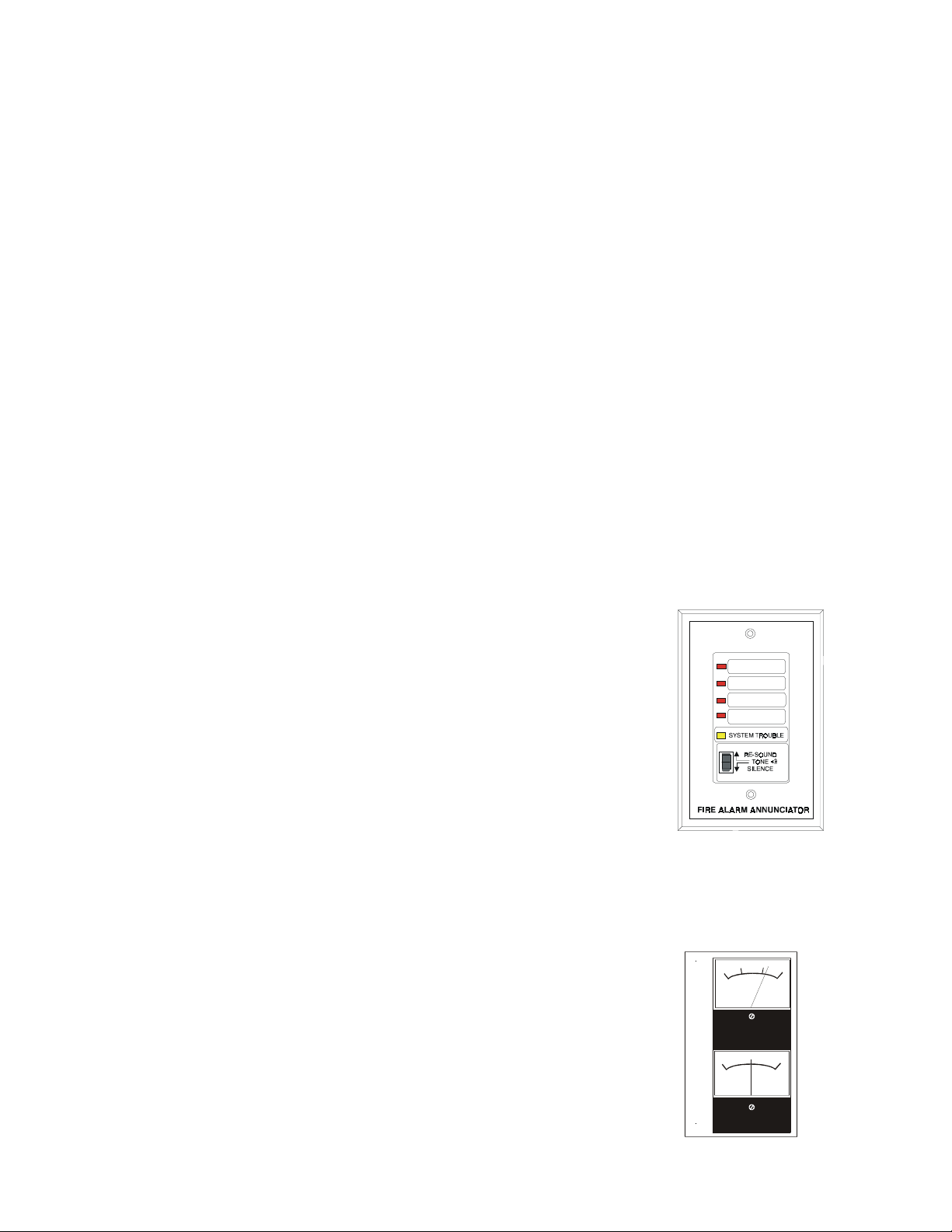
Remote Annunciator
Optional Meters
Remote Annunciator (RZA-4X - NOTIFIER)
The Remote Annunciator mounts on a standard singlegang box, and provides LED indication of the same
functions as the zone relay module. For example with
DIP 1=ON and DIP 2=OFF:
• One Zone in Alarm (red)
• Two Zones in Alarm (red)
• Releasing Circuit 1 (red)
• Releasing Circuit 2 (red)
• System Trouble (yellow)
A Local Trouble Sounder and Silence Switch are also
provided. All LED wiring is supervised for open
conditions. Any open condition will cause the System
Trouble LED to illuminate.
Note: The Remote Annunc iator requir es the use of an LED Interface m od ule (4XLM).
Voltage, Current Meters (4XMM - NOTIFIER)
The Meter Module provides a voltmeter to measure the
voltage across the batteries and an ammeter to measure
the charging current to the batteries. The meters are
provided as an assembly that mounts to the lower lefthand corner of the cabinet.
20
10
DC VOLTS
0
30
5
0
5
DC AMPERES
The PDRP-1002 PN 51135: A 03/11/99 9
Page 10

1 The PDRP-1002/PDRP-1002E
AC Circuit
Breaker
Acctbrkr.cdr
Specifications
AC Power
For the PDRP-1002: 120 VAC, 50/60 Hz, 1.2 amps
For the PDRP-1002E: 220/240 VAC, 50 Hz, 0.6 amps
Wire size: minimu m #14 AWG with 600V insulation
Battery (lead acid only)
Maximum Charging Circuit: 27.6V, 1.5 amps
Maximum Battery Capacity: 15 AH. (Batteries larger
than 12 AH require NOTIFIER #BB-17 or other UL
listed external battery cabinet.)
Initiating Device Circuits
Power-limited circuitry
Operation: Class A (Style D)/Class B (Style B)
Normal Operating Voltage: 24 VDC (ripple = 1.0V peak-to-peak)
Alarm current: 15 mA minimum
Short circuit current: 40 mA maximum
Maximum detector current in standby: 2 mA (max) per zone
Maximum loop resistance: 200 ohms
End-of-line resistor: 4.7K, 1/2-Watt (NOTIFIER part # 71252, UL listed)
Detector loop current is sufficient to ensure operation of one alarmed detector per zone.
Supervisory current: 5 mA (including end-of-line resistor)
AC Power
Notification Appliance and Releasing Circuits
Power-limited circuitry
Maximum allowable voltage drop due to wiring: 2 VDC
Normal Operating Voltage: 24 VDC
Total current available to all external devices: 2.25 amps
Maximum signaling current per circuit: 1.5 amps
End-of-line resistor: 4.7K, 1/2-Watt (NOTIFIER part # 71252, UL listed)
Alarm and Trouble Relays
Dry Form-C contacts rated: 2.0 amps @ 30 VDC (resistive), 0.5 amps @ 30 VAC
(resistive). All relays must be connected to a power limited power supply.
Four-wire Smoke Detector Power
Up to 200 mA is available for powering 4-wire smoke detectors.
Maximum ripple voltage: 1.0 V p/p
Non-resettable Power
Total DC current available from this output is up to 200 mA (subtracted from 4-wire
smoke power).
Maximum ripple voltage: 1.0 V p/p
RMS Regulated Power
Total DC current available for powering external devices is 0.5 amp (subtracted from
2.25 amps available to notification appliance circuits).
Maximum ripple voltage: 100 mV p/p
Note: For device compatibility, refer to Device Compatibility Chart.
10 The PDRP-1002 PN 51135:A 03/11 / 99
Page 11
RMS Regulated Power
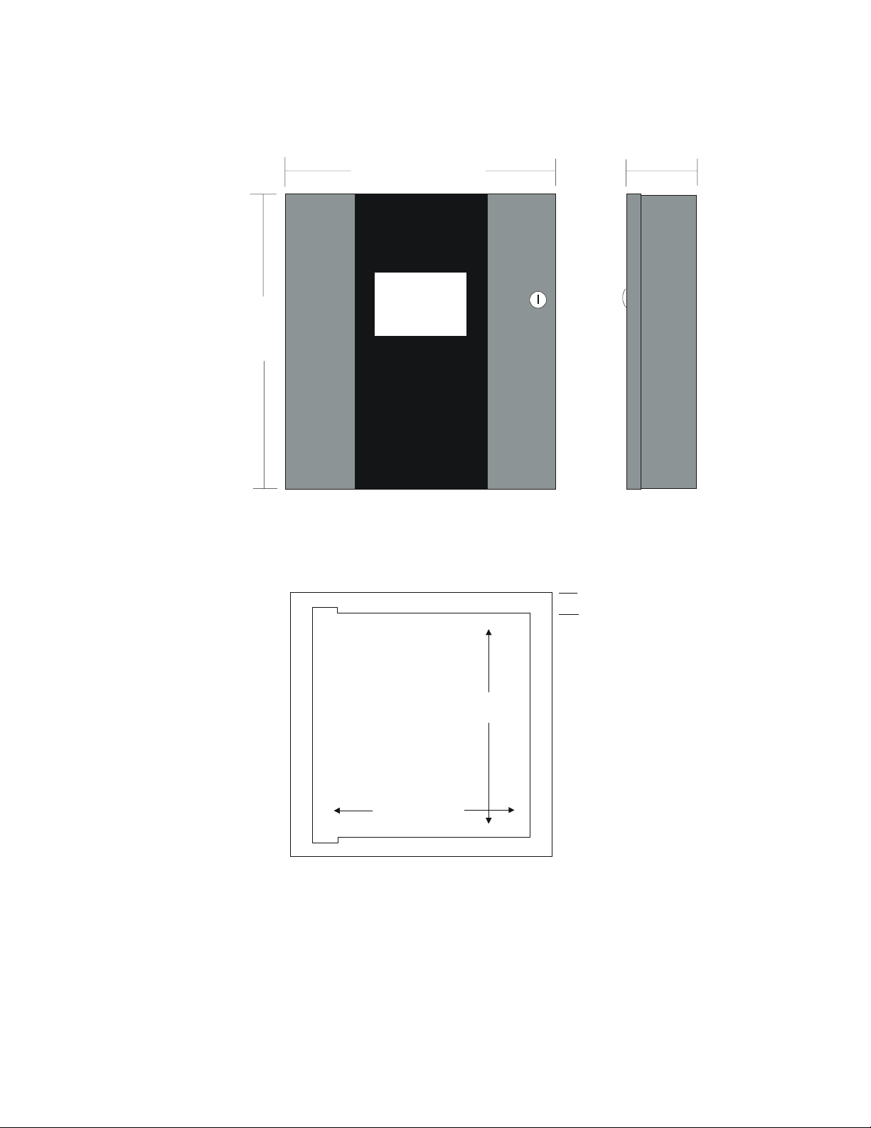
Door = 16.125 in.
(409.58 mm)
Backbox = 16 in.
(406.4 mm)
Door = 14.625 in.
(371.48 mm)
Backbox = 14.5 in.
(368.3 mm)
1 The PDRP-1002/PDRP-1002E
Cabinet = 5.375 in.
(136.53 mm)
Backbox = 4.750 in.
(120.65 mm)
TR-4XR
RUBY RD
STEEL
16 GA.
14.594 in.
(370.69 mm)
Optional Trim Ring
TR-4XR
Figure 2 Cabinet Dimensions
1.5 in
(38.1 mm)
16.094 in.
(408.79 mm)
RPCABDIM.cdr
The PDRP-1002 PN 51135: A 03/11/99 11
Page 12
2 System Operation
2 System Operation
WARNING:When used for CO2 releasing applications, observe proper
precautions as stated in NFPA 12. Do not enter the protected space unless physical
!
lockout and other safety procedures are fully completed. Do not use software
disable functions in the panel as lockout.
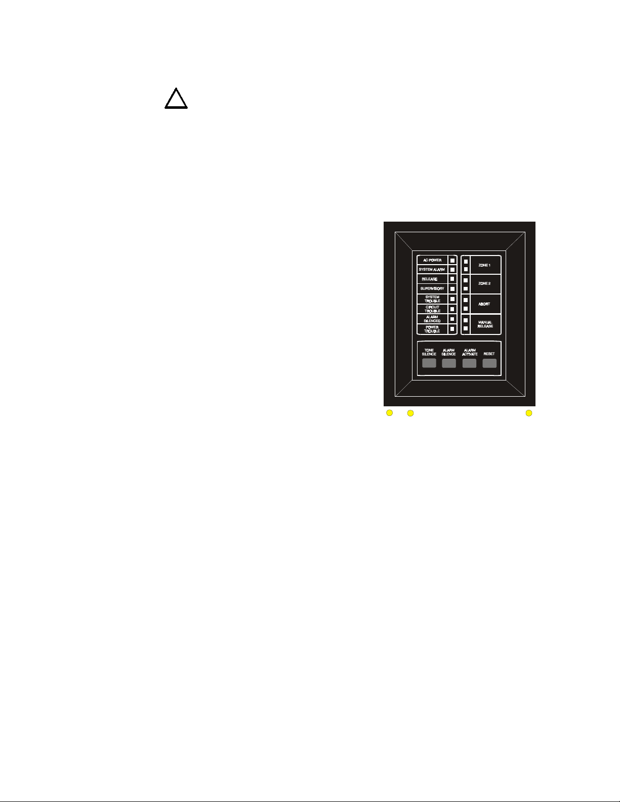
System Status LEDs
Alarm, Trouble and Supe rvisory LEDs will flash on and off until the event(s) has been
acknowledged (TONE or ALARM SILENCE), at which point the LED will illuminate
steadily.
AC POWER
Green LED that illuminates steadily to
indicate presence of AC power.
SYSTEM ALARM
Red LED that flashes when an alarm
occurs.
RELEASE
Red LED that illuminates steadily when
release occurs.
RMS Regulated Power
SUPERVISOR Y
Yellow LED that flashes upon activation of
a supervisory device (such as tamper
switch) on Output 4 if selected (see
“Setting Mode of Operation” in Section 3
of this manual).
SYSTEM TROUBLE
BATT
EARTH
MICRO
FAIL
Yellow LED that flashes for any trouble
condition, including those associated with option boards.
CIRCUIT TROUBLE
Yellow LED that flashes for trouble conditions on output circuits (notification and
releasing circuits).
ALARM SILENCED
Yellow LED that illuminates steadily when the ALARM SILENCE switch has been
pushed after an alarm.
POW ER TROUBLE
Yellow LED that flashes for low or disconnected batteries and earth fault conditions.
BA TT
Yellow LED that illuminates steadily on mother boar d when battery is low or not
detected (not visible through door).
EARTH
Yellow LED that illuminates steadily on mother boar d during a ground fault condition
(not visible through door)
4Xoper2.cdr
MICRO FAIL
Yellow LED that illuminates on motherboard when watchdog timer de tects
microprocessor failure (no t visi b le throu gh doo r)
12 The PDRP-1002 PN 51135:A 03/11 / 99
Page 13
RMS Regulated Power
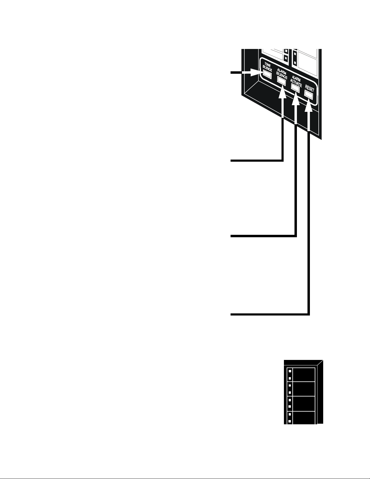
Control Switches
2 System Operation
Tone Silence
Acknowledge alarms, troubles and
supervisories. The panel has alarm and
trouble resound with LED flash of new
conditions. The flashing trouble LED(s)
illuminate steadily on TONE SILENCE and
the piezo sounder silences. A second trouble
will resound the piezo. The piezo has three
sounds for alarm, trouble, and supervisory.
Trouble cond i tio ns are self- res to ring . Alar ms
latch and require RESET to clear.
Alarm Silence
Acknowledge for alarms and supervisories.
The ALARM SILENCE switch will silence
the local piezo, change any flashing alarm
LEDs to steady, and turn off the notification
circuits (not the releasing circuits). The
“ALARM SILENCED” LED will illuminate.
Alarm silence is a latching function and
requires a RESET to clear.
Alarm Activate
The ALARM A CTIVATE switch may be used
to activate Notification Appliance Circuits.
ALARM ACTIVATE also activates the
System Alarm relay. ALARM Activate is a
latching function. Pressing ALARM
SILENCE silences the notification circuits
and System Alarm Relay and lights the Alarm
Silenced LED. Pressing RESET returns the
system to normal.
System Reset
The RESET switch breaks power to all
initiating circuits, 4-wire smoke power and
option boards and will clear any activated
output circuits. If any alarms or troubles still
exist after reset, they will reacti vate th e panel.
Holding RESET down will perform a LAMP
TEST function and will activate the piezo sounder.
4XPTL.cdr
Zone Status LEDs
The alarm and/or trouble LED(s)
will flash until the event(s) has
been acknowledged (TONE or
ALARM SILENCE), at which
point the LED(s) will illuminate
steadily.
ABORT TROUBLE LED
MANUAL RELEASE TROUBLE LED
The PDRP-1002 PN 51135: A 03/11/99 13
ALARM LED
TROUBLE LE D
ALARM LED
TROUBLE LE D
ABORT LED
MANUAL RELEASE
Zone 1
Zone 2
Abort
Manual
Release
Page 14
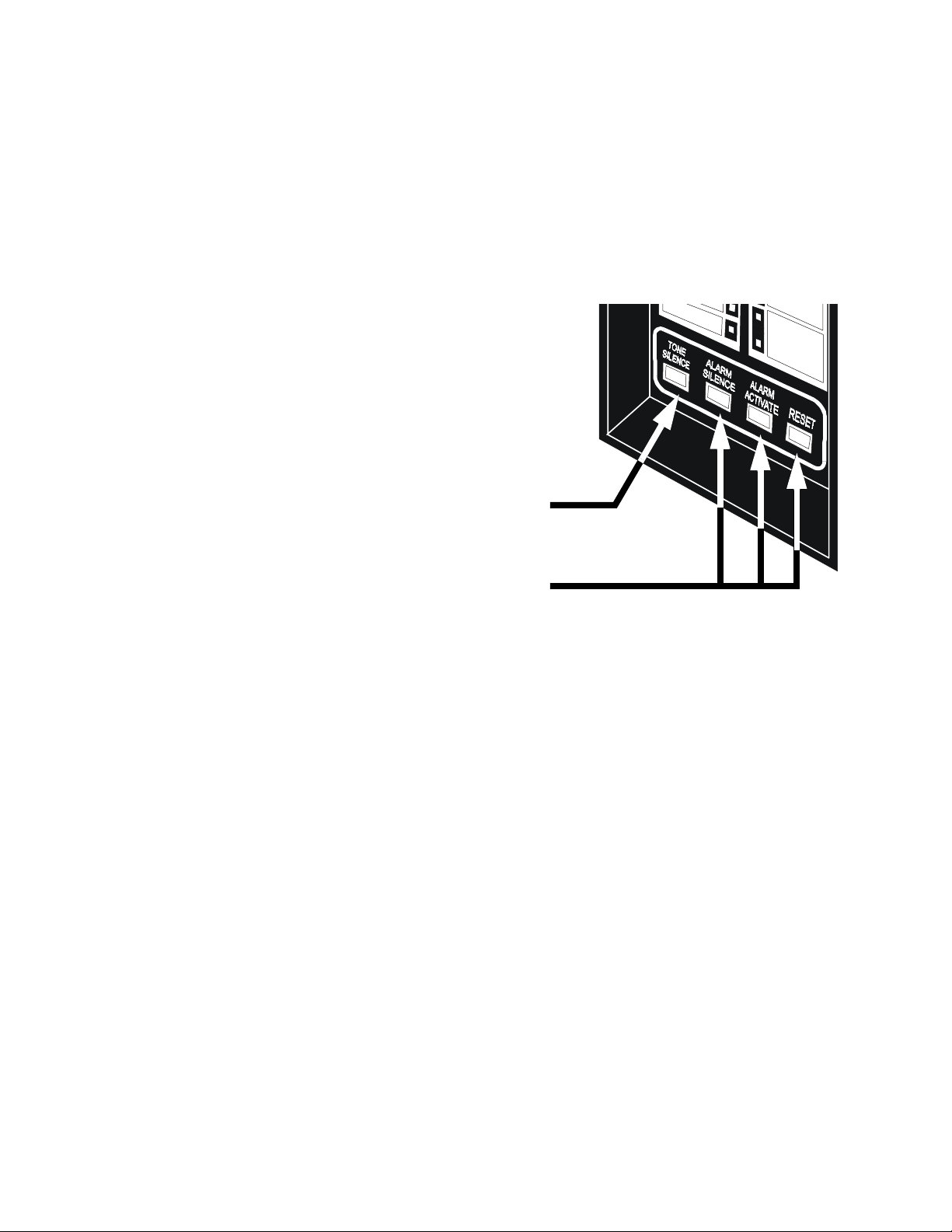
2 System Operation
Supervisory
Zone Disable
RMS Regulated Power
Output circuit #4 is used as an input for monitoring supervisory devices such as valve
tamper switches (note that SW1 DIP switch #2 must be set “ON” -- see section “Setting
Mode of Operation”) By setting Switch short circuit on this input (activation of a N.O.
contact) will cause the supervisory LED to flash. The piezo sounder will generate a
unique sound. TONE SILENCE will silence the piezo and cause the LED to illuminate
steadily. Supervisory signals latch and require RESET to clear . An open circuit will be
reported as a circuit trouble.
If a zone has been disabled, an alarm
that occurs on that zone will flash the
red zone LED, but not the p iez o or any
output circuit.
If both power sources
are removed from the system, all zones
will be re-enabled upon restoration of
power. Disable status will be lost .
The Zone Disable routine m akes use of
the four panel switches as follows:
1. Press and hold in the TONE
SILENCE switch.
Last Event Recall
2. With the TONE SILENCE switch
held in, press (in sequence) the
ALARM SILENCE switch, the
ALARM ACTIVATE switch, and
then the RESET switch.
3. The Zone 1 Alarm LED will flash.
4. To disable Zone 1, press the RESET switch. The Zone 1 yellow LED will light to
show that the zone is disabled.
Note: The RESET switch toggles disable status for the selected zone.
5. To select the next zone, press the ALARM SILENCE switch.
6. To select the previous zone, press the ALARM ACTIVATE switch.
7. When disable selections are complete, release the TONE SILENCE switch.
If any zone has been disabled, the trouble relay will activate and System Trouble LED
will flash.
Last Event Recall allows the user to display the previous panel status. The last event
recall uses the four panel switches as follows:
1. Press and hold in the TONE SILENCE switch.
4XPTL.cdr
2. With the TONE SILENCE switch held in, press (in sequence) the RESET switch,
the ALARM ACTIVATE switch, and then the ALARM SILENCE switch.
3. Last Event is displayed.
4. Release the TONE SILENCE switch to return to normal operation.
Note: To clear the last event buffer, press RESET twice.
14 The PDRP-1002 PN 51135:A 03/11 / 99
Page 15

UL Power Limited Wiring Requirements
imited
3 Installation Procedur e
General
Carefully unpack the system and check for shipping damage. Mount the cabinet in a
clean dry, vibration-free area in which extreme temperatures are not encountered. The
location should be readily accessible with sufficient room for easy installation and
maintenance. Locate the top of the cabinet approximately f ive feet abov e the floo r with
the hinge mounting on the left. Determine the number of conductors required for the
devices to be employed. Pull required conductors into the box through the knockout
provided. All wiring should be in accordance with the National and/or Local codes for
fire alarm systems.
UL Power Limited Wiring Requirements
Power limited and non-power limited circuit wiring must remain separated in the
cabinet. All power limited circuit wiring must remain at least 0.25 in (6.35 mm) away
from any non-power limited circuit wiring. Furthermore, all power limited circuit
wiring and non-power limited circuit wiring must enter and exit the cabinet through
different knockouts and/or conduits. A typical wiring diagram for the PDRP-1002/
PDRP-1002E is shown below.
3 Installation Procedure
AC Power
Power L
Circuits
Notification Appliance
Circuits
Non-Power
Limited Circuits
R
e
la
PC Board
Power Limited
Circuits
y
s
I
n
it
ia
ti
n
g
C
i
r
c
u
it
s
4XTM
Power Limited
Circuit
4XZM
Non-Power
Limited Circuit
RP1002PL.cdr
Figure 3 Typical Wiring Diagram for UL Power Limited Requir emen t s
The PDRP-1002 PN 51135: A 03/11/99 15
Page 16
3 Installation Procedure
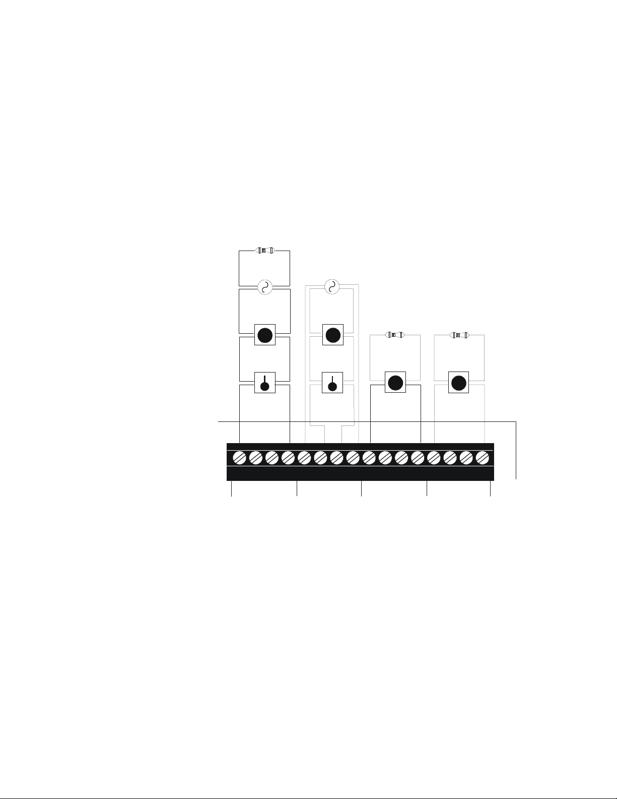
Initiating Device Circuits
Zones
Wire all alarm initiating devices sequentially for proper supervision. Initiating devices
include: heat, photoelectric, and ionization type detectors; and waterflow alarm
devices. Refer to the Compatibility Chart in Appendix B.
Note:
• Observe polarity when connecting polarized devices.
• All circuits are supervised and power limi te d.
• Leave Dummy Load (provided) on al l unused circuits.
4.7K, 1/2-Watt (part # 71252 UL listed)
Two-wire
Smoke
Detector
Heat
Detector
Class B (Style B)
Initiating Device Circuit
Class A (Style D)
Initiating Device
+
+
_
_
+
+
Circuit
_
_
Abort Switch
4.7K, 1/2-Watt
(part # 71252
UL listed)
Manual Release
4.7K, 1/2-Watt
(part # 71252
UL listed)
Zones
Manual
Pull Station
TB4
+
B+ A+ A-
1234
_
+
B+ A+ A-
B-
5678910
_
B-
B+ A+ A-
11 12
B+ A+ A-
B-
13
IN #1 IN #2 IN #3 IN #4
Figure 4 Example of an A larm Initiating Device
14
B-
15 16
AIDEX.cdr
16 The PDRP-1002 PN 51135:A 03/11 / 99
Page 17

Zones
4-Wire Smoke Detector Connections
Refer to the Device Compatibility Document for suitable 4-wire smoke detectors.
3 Installation Procedure
24 VDC (+)
+ +
Common (-)
-
-
IDC (+)
+ +
-
-
IDC (-)
Four-wire Smoke Detectors
TB1
+
-
1234
+24VR
A maximum of 200mA is available from the +24VDC
4-wire smoke detector power circuit on TB1 terminals 3
and 4. Any power that is drawn from the +24VDC Nonresettable Power on TB2 terminals 1 an d 2 mu st be
subtracted from available 4-wire detector power. (See
“Specifications” and “Power” sections.)
UL listed 24 VDC
Class B Initiating Device Circuit
24 VDC (+)
+ +
Common (-)
-
-
IDC (+)
+ +
-
-
IDC (-)
Red
Black
UL listed
4.7K, 1/2-Watt
ELR
TB4
B+ A+ A- B-
1234
IN #1
Initiating Device Circuits 1,2, 3, or 4
can be used. Class A (Style D) wiring
can also be employed.
Listed
Power
Supervision
Relay
RP4WR.cdr
Figure 5 Diagram of Connections for a 4-Wire Smoke Detector
Notes on Class A (Style D) and Class B (Style B) field wiring:
1) The Power Supervision Relay coil leads must be connected to the last detector
base 24V screw terminals.
2) Calculation of the maximum allowable resistance in the 24VDC detector power
wiring:
R
Where:
R
is the maximum resistance of the 24V wires.
MAX
V
is the minimum operating voltage of the detector or end-of-line relay, whiche ver is
OM
greater, in volts.
N
is the total number of detectors on the 24V supply loop.
I
is the detector current standby.
S
N
is the number of detectors on the 24V power loop which must function at the same
A
time in alarm.
I
is the detector current in alarm.
A
I
is the end-of-line relay current.
R
= (20.6 - VOM)
MAX
_________________________________________________________________________________________
(N x I
) + (NA x IA) + (IR)
S
The PDRP-1002 PN 51135: A 03/11/99 17
Page 18

3 Installation Procedure
a
,
Output Circuits
Notification Appliance Circuits
Notification Appliance Circuits
This control panel can provide two Class A (Style Z)/Class B (Style Y) Notification
Appliance Circuits and two Class B (Style Y) Releasing Circuits (see section “Setting
Mode of Operation” for DIP switch configuration). Each circuit is capab le of 1 .5 am ps
of current. Total current drawn from all four circuits cannot exceed 2.25 amps. Refer
to the Compatibility Chart. Circuits are supervised and power-limited.
Note: Wirin g mu st be configured to maintain a minimum volta ge o f 20.4V on release circuits. Calcu lat ion of
maximum allowable resistance:
= 20.6V-20.4V
________________________________________________________________________
R
MAX
Where:
Class A
(Style Z)
Notification
Applianc e Circuit
R
= maximum allowable resistance of wiring
MAX
I
= solenoid current
S
Class B (Style Y) Notification
Applianc e Circuit
4.7K, 1/2-Watt
(part #71252 UL listed)
I
S
Polarized Bell
Polarized Strobe
Polarized Horn
TB2
+
-
+ -
B+ A+ A-
345678910111213141516
OUT #1
4.7K, 1/4-Watt
B+ A+ A-
B-
+
+ -
OUT #2
-
Releasing Circuits
UL listed & FM approved
Releasing Devices
No Connection
NCNCB+ B-
B-
OUT #3
4.7K, 1/4-Watt
No Connection
B+
B-
OUT #4
See note
below
Dummy Load all
unused Notification
Appliance Circuits
Note: Output #4 can be configured for relea sing or supervisory circuit (see Section “Se tt in g M ode of O pe r
configured as a releasing circuit, the circuit will be non-power limited. If configured as a supervisory circuit
will be power limited. All wiring must follow the power limited “General” Section.
B+ A + A-
B-
B+
Dummy Load all
B-
unused Releasing
Circuits
Figure 6 Notification Appliance Circuits
18 The PDRP-1002 PN 51135:A 03/11 / 99
RPNAC.cdr
Page 19

Alarm Relay
3 Installation Procedure
Alarm Relay
One Form-C dry alarm contact is provided in the basic panel for controlling
supplementary devices. It is rated 2 amps at 30 VDC and 0.5 amps at 30 VAC
(resistive), and is non-silenceable when an alarm occurs. See below for terminal
location.
Trouble Relay
One Form-C dry trouble contact is provided in the basic panel for controlling
supplementary devices. It is rated 2 amps at 30 VDC and 0.5 amps at 30 VAC
(resistive), and will silence when trouble condition is cleared. See below for terminal
location.
Note: The alarm and tr ouble Form-C dry contact relay s must be power limited relays. They must be wired
from one of the 24V power limited ter mi nals as shown in the figure below or a comparable UL liste d power
limited power supply.
Alarm
NO NC C
Trouble
NO NC C
Power
or
TB1
1234 12
+24VU +24VR
or
+24VNR
TB2
TB3
1234
Alarm
Schematic representa tion of
Alarm/Trouble coil s and c ont acts.
56
Trouble
Figure 7 Alarm/Trouble Coils and Contacts
CAUTION: Several different sources of power can be connected to this panel.
!
Disconnect all sources of power before servicing. The pane l and associated equipmen t
may be damaged by removing and/or inserting cards, modules, or interconnecting
cables while this unit is energized.
This output is not suitable
for powering devices
requiring fil tered DC power.
RMS-Regulated Power
24 VDC power for inductivetype devices such as door
holders can be connected to TB1
terminals 1 (+) and 2(-).
The combined current draws from the Resettable
and Non-resettable outputs cannot exceed 200 mA.
4-Wire Smoke Detector Power
24 VDC filtered, resettable power
for 4-wire smoke detectors can be
obtained from TB1 Terminals 3(+)
and 4(-).
Non-resettable Power
24 VDC filtered, nonresettable
power can be drawn from TB2
Terminals 1 (+) and 2(-).
RPALMTBL.CDR
+24VU
+ - + -
TB1
+24VR +24VNR
+ -
TB2
1234 12
Figure 8 Diagram of Power Termi nals
The PDRP-1002 PN 51135: A 03/11/99 19
RPPWRTRM.cdr
Page 20

3 Installation Procedure
AC Power
Primary power required for the PDRP-1002 panel is 120 VAC, 50/60 Hz, 1.2 amps and
primary power for the PDRP-1002E is 220/240 VAC, 50 Hz, 0.6 amps. Overcurrent
protection for this circuit must comply with Article 760 of the National Electrical Code
(NEC) and/or local codes. Use #14 AWG (2.00 mm
2
)or larger wire with 600 volt rating.
Battery Power
Observe polarity when connecting battery. Connect battery cable to J9 on the main
board using the plug-in connector provided. See Appen dix A for calcul ation of correct
battery rating.
CA UTION: Batteries contain s ulfuric acid which can cause se ver e b urns to the skin and
!
eyes, and can destroy fabrics. If contact is made with sulfuric acid, immediately flush
skin or eyes with water for 15 minutes and seek immediate medical attention.
Voltmeter/Ammeter
To monitor battery voltage and battery charging current, a 4XMM (NOTIFIER) is
required. To install the power meter module, remove the jumper labeled “AMP” and
connect cable assembly P2 to pin connector J2 and cable assembly P3 to pin connector
J3 on the main board. Secure the 4XMM to the backbox with the two screws provided.
On some models, it will be necessary to install the meter b racket with the nuts and bolts
provided.
AC Power
5
0
10
DC VOLT S
0
DC AMPERES
P2
20
J2
J9
P3
J3
30
5
RPMBVM.cdr
Figure 9 Diagram of the 4XMM Voltmeter Connected to the Main Board
20 The PDRP-1002 PN 51135:A 03/11 / 99
Page 21

Voltmeter/Ammeter
Optional Modules
Transformer
Ground
Neutral
Hot
Optional Ammeter
Connection
3 Installation Procedure
The fire control panel has two module connectors - J5 and J8. Three modules are
available for the panel and they can be used in any combination, including duplicate
modules. The corresponding option jumper must be cut before installation of an
optional module.
J4
*Jumper “OPT 1”
J5
must be cut if a
module is
installed in this
position
Batteries
Optional
VoltmeterConnection
J7
J8
Cross Zone
Supervisory
Ground Fault LEDBattery Fail LED
Note:
• Optional 4XLM module for an RZA-4X Annunciator mu st be inst al le d on J7 and J8
• 4XTM and 4XZM module s can be in sta ll ed in ei th er location.
Delay Timer
Figure 10 Optional Panel Modules
Abort Option
Abort Option
Delay Timer
Micro Fail LED
*Jumper “OPT 2”
must be cut if a
module is
installed in this
position
only
.
4XRP102a.cdr
The PDRP-1002 PN 51135: A 03/11/99 21
Page 22

3 Installation Procedure
Installing Option Modules
Installing Option Modules
Insert the two stand-offs (provided) into the holes located on the right-side edge of the
main board. Carefully align the pins on the main board with J1 and/or J2 on the option
board. Insert screw through the option board until it is secured on the stand-offs. Affix
the terminal identification labels provided with the option modules as shown below.
(Part # 42050)
Stand-offs)
Option Board
(4XZM shown)
Main
Board
4XSTNOFF.cdr
4XOPTNBD.cdr
Figure 11 Installing Option Modules.
22 The PDRP-1002 PN 51135:A 03/11 / 99
Page 23

Transmitter Module - 4XTM (NOTIFIER)
Transmitter Module - 4XTM (NOTIFIER)
Polarities shown in activated positions. The wiring of this module must follow the
requirements as specified in the “General” section, “
Requirements.
3 Installation Procedure
UL Power Limited Wiring
”
1
2
3
4
5
6
7
TBL Jumper
Disconnect LED
4XTBa.cdr
Disconnect Switch
+
Remote Alarm
}
-
+
Remote Trouble
}
-
No Connection
+
Municipal Box*
}
-
Power Limited Circuit
Non-Power Limited Circui
* Dummy load terminals
6 and 7 (4.7K, 1/4 W
resistor) if Municipal
Box is not connected.
Push the disconnect switch down to prevent unwanted activation of the Municipal Box
and Remote Station Outputs during testing of the control panel. The Disconnect LED
will remain illuminated while the Municipal Box is disconnected. The System Trouble
LED will indicate disconnected and/or Open Circuit conditions on the Municipal box.
Cutting the TBL jumper will allow the alarm reverse polarity circuit to open on tr ouble,
if no alarm exists
Note: Remote Alarm, Remote Trouble, and Municipal Box wiring can leave the building.
.
The PDRP-1002 PN 51135: A 03/11/99 23
Page 24

3 Installation Procedure
Zone Relay Module - 4XZM (NOTIFIER)
Zone Relay Module - 4XZM (NOTIFIER)
Non-power li mited and po w er limited wiring mu st h ave a minimum distance of 0.25 i n.
(6.35 mm) wire to wire. If this module is used to drive non-power limited and power
limited circuits, please follow the instructions below.
Relay #1 through #4 will activa te w it h Output #1 through #4
and remain latched unless jumper “LATCH” is cut.
1 NO
2 NC
3 C
4 NO
5 NC
6 C
7 NO
8 NC
9 C
10 NO
11 NC
12 C
13 NO
14 NC
15 C
16 NO
17 NC
18 C
4XZMA.cdr
Use Disable switch to disconnect the relays.
Cut jumper fo r no n -latching (s ilenceable) r elay operati o n.
Relay #1
Relay #2
Relay #3
Relay #4
Alarm
Trouble
1) Skip a set of dry contacts to maintain the 0.25 in (6.35 mm) required space
between power limited and non-power limited circuits. The wiring of this module must
follow the requirements as specified in the “
Wiring Requirements
.”
General
” section, “
UL P ower Limited
OR
2) If this module is needed to drive power limited and non-power limited relays that
are next to each other, refer to the figure below showing a typical connection.
Relay #1
Relay #2
Relay #3
Relay #4
Note: Refer to the Protected Premises Unit label, located on the door of the control panel, to
indicate if any dry contacts are t o be use d as non-power limited dry contacts.
NO
NC
C
NO
NC
C
NO
NC
C
NO
NC
C
Power Limited Circuit
Power Limited Circuit
No Connection
Non-power Limited Circuit
Non-power Limited Circuit
4XZMptl.cdr
24 The PDRP-1002 PN 51135:A 03/11 / 99
Page 25

LED Interface Module - 4XLM (NOTIFIER)
LED Interface Module - 4XLM (NOTIFIER)
The wiring of this module must follow the requirements as specified in section”
Requirements
.”
3 Installation Procedure
UL Power Limited Wiring
1 +24V
2 Out#1
3 Out#2
4 Out#3
5 Out#4
6 System Trouble
7 Sound
8 Resound
4XLMa.cdr
Front View
Connect to corresponding terminals
of RZA-4X Remote Annunciator.
RZA4XBX.cdr
RZA4Xfr.cdr
Side View
Single-gang Box
Note: Make wiring connections with system
power off. Maximum wire impedance is 50
ohms per wiring connection .
Figure 12 LED Interface Module - 4XLM
The PDRP-1002 PN 51135: A 03/11/99 25
Page 26
3 Installation Procedure
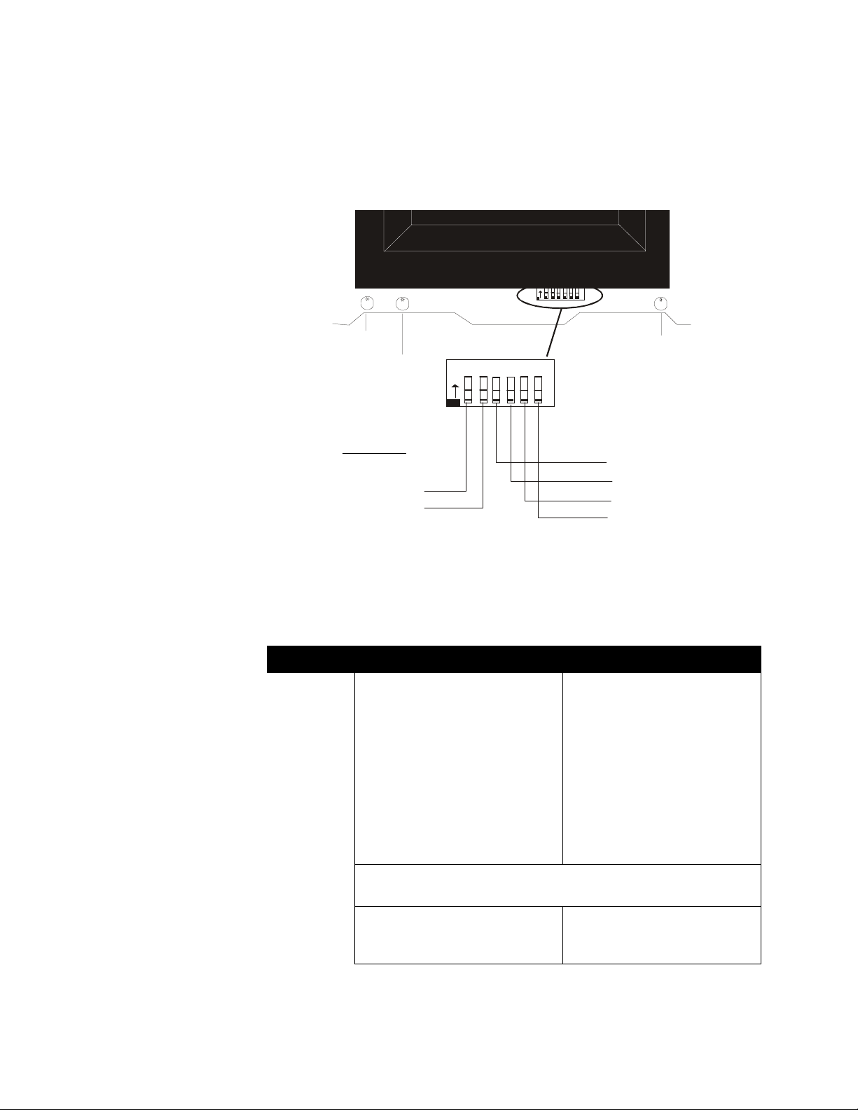
Setting Mode of Operation
DIP Switch
The DIP switch is located at the bottom of the PDRP-1002/PDRP-1002E main board.
To set a switch to the “ON” position, slide the switch up until it stops. The flushsurface switches are designed to pre v ent accidentally changing a switch setting and may
therefore require use of a pen or screwdriver to set them.
O
123456
N
DIP Switch
4XRPDIPS.cdr
Battery Fail
LED
Ground Fault LED
DIP Switches
Switch 1: CROSS ZONE
Switch 2: SUPERVISORY
Note: The Reset key must be depressed af te r any switch configuration has been made.
O
123456
N
Micro Fail LED
Switch 3: DELAY TIMER
Switch 4: DELAY TIMER
Switch 5: ABORT OPTION
Switch 6: ABORT OPTION
Cross Zone
Select the desired mode of operation and set SW1 DIP switch 1.
Switch 1 OFF ON
Output 1
Zone 1
either
is activated by an alarm on
Zone 2
or
.
Output 1
(Pre-discharge alarm) is
activated by the first alarmed zone
in the system. Initiation of an alarm
on the other zone will shut this
output off.
Output 2
either
is activated by an alarm on
Zone 1
or
Zone 2
. Output 2
will pulse at 60 ppm while timer is
running or frozen by abor t. Output 2
will sound steadily upon release (time
out).
Outputs 3 and 4
will be activated when the timer expires (provided that
Output 2
occur on both
is activated when alarm s
Zone 1
and
Zone 2
Output 2 will pulse at 60 ppm while
timer is running or frozen by abort.
Output 2 will sound st eadily upon
release (time out).
.
Output 4 is functioning as a releasing circuit - set via DIP Switch 2).
Timer
The
alarm occurs on either
Zone 2
Note: Outputs 1 and 2 refer to Notification Appliance Circuits. Output 3 refers to a releasing circuit. Output
4 is determined by setting switch 2. Zones 1 and 2 re fe r to In it ia ting D evice Cir cuits.
26 The PDRP-1002 PN 51135:A 03/11 / 99
will start whenever an
Zone 1
.
or
Timer will start
The
occur on both
Zone 1
when alarms
Zone 2
and
.
Page 27

Output 4 Supervisory/Releasing Service
Output 4 Supervisory/Releasing Service
Set the function of Output 4 via SW1 DIP switch 2.
Switch 2 OFF ON
3 Installation Procedure
Output 4
solenoid releasing circuit. This
circuit will be a non-power
limited circuit in this mode.
will function as a
Output 4 will function as a supervisory input
circuit. A short condition on this circ uit will
illuminate the Supervisory LED and sound
the supervisory ton e on the piezo. An open
condition generates a circuit trouble
condition. This circuit will function as a
power limited circuit in this mode.
Timer
Select the desired Timer setting and set SW1 DIP switches 3 and 4 per the appropriate
column.
No Delay* 10 Seconds 20 Seconds 30 Seconds
Switch 3 OFF OFF ON ON
Switch 4 OFF ON OFF ON
*Abort switch is inoperative when no delay is selected.
Abort Function
Select the desired abort funct ions and set SW 1 DIP switc hes 5 and 6 per the appr opriate
column.
Switch 1 OFF OFF ON ON
Switch 2 OFF ON OFF ON
Standard UL-type
delay
timer which
continues to count down
upon ABORT , and stops
and holds at 10 seconds
until release of the
ABORT switch. Upon
release of the ABORT
switch, the timer
resumes the countdown
at 10 seconds.
These modes are the onl y on es t hat
comply with UL Standard 864
Note: ABORT timer will not operate when timer is set for “NO DELAY”.
IRI-type delay
timer
which
functions the same as
the UL-type timer
with the except ion
that the ABORT will
function only if
pressed and held
before 2nd zone goes
into alarm.
NYC-type delay
timer.
Pressing
ABORT, once an
alarm exists, changes
timer value to the
time selected via DIP
Switches 3 and 4
plus 90 seconds.
The timer will not
start as long as the
ABORT switch is
held. SYSTEM
RESET restores
timer to original
times selected via
DIP Switches 3 and
4. Successive
ABORTS will add
90 seconds to
selected timer value.
Local Jurisdiction
delay timer.
the timer has started,
pressing ABORT
restores timer to its
full time as s e t o n
DIP Switches 3 and
4. The timer will
not start as long as
ABORT is held.
Release of the
ABORT switch
continues the
countdo wn, where as
pressing ABORT
again will restore
the timer to its full
value.
Once
The PDRP-1002 PN 51135: A 03/11/99 27
Page 28

Appendix A: Power Calculations
Appendix A: Power Calculations
Standby Battery Requirements
The Standby Battery Current figure obtained in the following table (Table 1) represents
the amount of current that must be supplied by the secondary power source (batteries)
to sustain control panel operation for one hour.
Standby Battery Requirements
Basic Contro l Panel
Control panel with AC power off, System Trouble LED and audible trouble sounder on.
If using a 4XZM Zone Relay Module1 [ ] X 8 mA =
f using a 4XTM Transmitter Module, add 11 mA
If using the Reverse Polarity Alarm output, add 5 mA
If using the Reverse Polarity Trouble output, add 5 mA
If using a 4XLM/RZA-4X Driver/Annunciator combination:
1
[ ] X 19 mA =
If using a 4XMM Meter Module, add 1 mA
If using the Noti•Fire 911AC DACT, add 30 mA
Number
in use
(see Appendix B for data)
a. Two-wire detector he ads
Device
Current
X =
Total
Current
88 mA
b. Four-wire detector heads
c. End of Line Relays
d. Add lines a, b, & c for
X =
X 25.0 mA =
Place subtotal here
Add last column for Standby Battery Current :
and continue to next table (Table 2)
Table 1 Standby Battery Requirements
Note: The control panel will support the installation of one or two optional modules, inc lu ding two of the
same type of module.
28 The PDRP-1002 PN 51135:A 03/11 / 99
Page 29

Ampere-Hour Calculations
Appendix A: Power Calculations
Ampere-Hour Calculations
Standby Battery Current
Convert the total from
Table 1 to amps and enter
here
amps X
Enter 0.25 for 5 minutes in alarm
or 0.5 for 10 minutes in alarm
Add Standby and A larm amp/h ours
Select a battery with an equal or greater amp/hour rating than the f igur e obtained
in
Table 2. Batteries must be lead-acid type.
PS-1270 12 volt, 7 amp/hour (two required)
PS-12120 12-volt, 12 amp/hour (two required)
StandbyTime
24, 60, or 90
hours
hours =
+
=
Table 2 Ampere-Hour Calcula t ions
Standby
amp/hours
Alarm
amp/hours
Total amp/
hours needed
Notes:
1. Alarm amp-hours assumes a maximum system draw of 3 amps in alarm for 5
minutes (0 .25 amp/hour) or for 10 minutes (0.5 amp/hour)
2. NFPA 72 Central Station and Local and Propri etary Fire A larm S ystems requir e 24
hours of standby.
3. NFPA 72 Auxiliary and Remote Station Fire Alarm Systems require 60 hours of
standby.
4. Factory Mutual Systems require 90 hours of standby.
5. The battery charger in this panel will charge a maximum of 15 amp/hours of
batteries within 48 hours (7 amp/ hour mini mum). Batteries larger than 12 amp/
hour will require a UL listed battery cabinet (e.g. NOTIFIER BB-17).
The PDRP-1002 PN 51135: A 03/11/99 29
Page 30

Appendix B: Device Compatibility
Appendix B: Device Compatibility
FM-Approved Releasing Devices
Smoke Detector/Base Detector Type
System Sensor 2424 Photoelectric 0.10 41
System Sensor 2424TH Photoelectric 0.10 41
System Sensor 2451 Photoelectric 0.10 39
System Sensor 2451TH (with/B402B Base) Photoelectric 0.10 39
System Sensor 1424 Ionization 0.10 41
System Sensor 1451 (w/B402B Base) Ionization 0.10 39
System Sensor 2412 Photoelectric 0.12 77
System Sensor 2412AT Photoelectric 0.12 58
System Sensor 2412TH Photoelectric 0.12 77
System Sensor 2312/24TB Photoelectric 0.12 50
System Sensor B112LP Base
System Sensor B114LP Base
System Senso r B404B Base
System Sensor 6424 Projected Beam 10 28.4
System Sensor DH400ACDCI Ionization Duct 25 95
Max Standby
Current (mA)
see note
see note
see note see note
Max Alarm
Current (mA)
39
75
System Sensor DH 40 0ACDCP Photoelectric Duct 25 95
System Sensor 1112/24 Ionization 0.05 50
System Sensor 2112/24 Photoelectric 0.05 50
System Sensor 2112/24B Photoelectric 0.05 65
System Sensor 21 12 /2 4T Photoelectric w/13 5°
Thermal
System Sensor 2112/24TSRB Photoelec tr ic w/135°
Thermal Supervisory Relay
Note: Contact manufacturer for currents.
0.05 50
15 45
Table 3 UL Listed Four-Wire Smoke Detectors
FM-Approved Releasing Devices
(System Sensor’s PDRP-1002/PDRP-1002E)
Solenoid Group [A]
Skinner solenoid valve Model LV2LBX25, 24 VDC, 11 Watts, 458 mA, 1/2 in. NPS, 5/
8 in. orifice.
Solenoid Group [B] These valves are interchangeable
ASCO solenoid valve Model T8210A107, 24 VDC, 16.8 Watts, 700 mA, 1/2 in. NPS,
5/8 in. orifice.
.
ASCO solenoid valve Model R8210A107, 24 VDC, 16.8 Watts, 700 mA, 1/2 in. NPS,
5/8 in. orifice.
ASCO solenoid valve Model 8210A107, 24 VDC, 16.8 Watts, 700 mA, 1/2 in. NPS, 5/
30 The PDRP-1002 PN 51135:A 03/11 / 99
Page 31

FM-Approved Releasing Devices
8 in. orifice.
Solenoid Group [C]
Star Sprinkler Corp. Solenoid P/N 5550, 24 VDC, part of Model D deluge valve.
Kidde-Fenwal Electric Control Head P/N 890181; 24V, 2.0 Amps
Kidde-Fenwal Electric Control Head P/N 899175; 24V, 2.0 Amps
Kidde-Fenwal Electric Control Head Stackable (XP) P/N 48650001; 24V, 0.2 Amps
Kidde-Fenwal Electric and Cable Op Control Head (XP) P/N 897494; 24V, 1.5 Amps,
33 Watts
Refer to the FM approval guide for automatic water control valves which are
compatible with solenoids listed above.
Appendix B: Device Compatibility
Model Type Current (mA)
FM980-24 Floor Mount, single 68
FM996-24 Wall Mount Surface Wiring 68
FM998-24 Wall Mount Concealed Wiring 68
Table 4 24 VDC Door Holders
Vendor Model Current(mA)
System Sensor A77-716B 20
Air Products & Controls, LTD MR-101/C
MR-201/C
15
35
Table 5 UL Listed 24 VDC Relays
The PDRP-1002 PN 51135: A 03/11/99 31
Page 32

Appendix B: Device Compatibility
FM-Approved Releasing Devices
SYSTEM SENSOR
System Sensor MA-12/24D Electronic Sounder 24VDC 73 46
System Sensor SS24 Strobe 24VDC
System Sensor SS24LO Strobe 24VDC 45 25
System Sensor SS24LOC Ceiling Strobe (SS24LOBC - beige) 24VDC 45 25
System Sensor SS24M Strobe 24VDC 125 75
System Sensor SS24MC Ceiling Strobe 24VDC 125 75
System Sensor MASS24D Electronic Sounder/Strobe 24VDC 118 71
System Sensor MASS24LO Electronic Sounder/Strobe 24VDC 118 71
System Sensor MASS24LOC Electronic Ceiling Sounder/Strobe 24VDC 118 71
System Sensor MASS24LOLA Electronic Sounder/Strobe with Fuego lens 24VDC 118 71
System Sensor MASS24M Electronic Sounder/Stro be 24VDC 198 121
System Sensor MASS24MC Electronic Ceiling Sounder/Strobe 24VDC 198 121
System Sensor PA400R Sounder 24VDC
System Sensor PS24LO Add-on Strobe 24VDC 45 25
Rated
Voltage²
FWR DCFiltered
DC
note 5
note 5
30
15
System Sensor SS24 15ADA Signaling Strobe 24VDC 90 75
System Sensor SS2475ADA Signaling Strobe 24VDC 200 170
System Sensor SS24110ADA Signaling Strobe 24VDC 245 210
System Sensor SS241575ADA Signaling Strobe 24 VDC 120 93
System Sensor SS24 15ADAS Signaling Strobe with Synch. Circuit 24 VDC 125 10 6
System Sensor SS241575ADAS Signaling Strobe with Synch. Circuit 24 VDC 180 115
System Sensor MASS2415ADA Sounder/Signaling Strobe 24VDC 163 121
System Sensor MASS2475ADA Sounder/Signaling Strobe 24VDC 273 216
System Sensor MASS 24110ADA Sounder/Signaling Strobe 24VDC 318 256
System Sensor MASS 241575ADA Sounder/Signali ng Strobe 24 VDC 193 139
System Sensor MASS 2415ADAS Sounder/Signaling Strobe w/ Synch. Ckt. 24 VDC 163 121
System Sensor MASS241575ADAS Sounder/Signaling Strobe w/ Synch. Ckt. 24 VDC 193 139
System Sensor PS24 15ADA Mini-Sounder/Strobe 24VDC 110 90
System Sensor PS24 75ADA Mini-Sounder/Strobe 24VDC 135 108
System Sensor PS241575ADA Mini-Sounder/Strobe 24VDC 135 108
System Sensor PS24110ADA Mini-Sounder/Strobe 24VDC 240 225¥
System Sensor SP1R2415ADA Speaker/Signaling Strobe 24VDC 90 75
System Sensor SP1R2475ADA Speaker/Signaling Strobe 24VDC 200 170
System Sensor SP1R24110ADA Speaker/Signaling Strobe 24VDC 245 210
32 The PDRP-1002 PN 51135:A 03/11 / 99
Page 33

FM-Approved Releasing Devices
System Sensor SP1R 241575ADA Speaker/Signaling Strobe 24 VDC 120 93
System Sensor V4R2415ADA Speaker/Signaling Stro be 24VDC 90 75
System Sensor V4R2475ADA Speaker/Signaling Strobe 24VDC 200 170
System Sensor V4R24110ADA Speaker/Signaling Strobe 24VDC 245 210
System Sensor V4R241575ADA Speaker/Signaling Strobe 24 VDC 120 93
System Sensor SP100W24LOC Ceiling Speaker/Stro be, 8" round grille 24VDC 45 25
System Sensor SP101R24LO Speaker/Strobe, 5" square grille 24VDC 45 25
System Sensor SP101R24M Speaker/Strobe, 5" square grille 24VDC 125 75
System Sensor SP100W24MC Ceiling Speaker/Strobe, 8" round grille 24VDC 125 75
Appendix B: Device Compatibility
System Sensor MA12/24EH Multi Alert Horn with Mechanical Tone 12VDC/
24VDC
System Sensor MAEH24LO Multi Alert Horn with Mechanical Tone/Strobe 24VDC 109 68
System Sensor MAEH24LOC Multi Alert Horn with Mechanical Tone/Strobe 24VDC 109 68
System Sensor MAEH24LOLA Multi Alert Horn with Mechanical Tone/Strobe 24VDC 153 96
System Sensor MAEH24M Multi Alert Horn with Mechanical Tone/Strobe 24VDC 189 118
System Sensor MAEH24MC Multi Alert Horn with Mechanical Tone/Strobe 24VDC 189 118
System Sensor MAEH1215ADA Multi Alert Horn with Mechanical Tone/Strobe 12VDC 240 191
System Sensor MAEH121575ADA Multi Alert Horn with Mechanical Tone/Strobe 12VDC 310 246
System Sensor MAEH2415ADA Multi Alert Horn with Mechanical Tone/Strobe 24VDC 278 216
System Sensor MAEH2475ADA Multi Alert Horn with Mechanical Tone/Strobe 24VDC 273 216
System Sensor MAEH241575ADA Multi Alert Horn with Mechanical Tone/Strobe 24VDC 343 271
System Sensor MAEH24110ADA Multi Alert Horn with Mechanical Tone/Strobe 24VDC 318 256
System Sensor MAEH2415ADAS Multi Alert Horn with Mechanical Tone/Strobe 24VDC 198 152
System Sensor MAEH241575ADAS Multi Alert Horn with Mechanical T one/Strobe 24VDC 253 241
System Sensor H12 Spect rAlert Horn 12VDC 25 14
20/64 38/43
System Sensor H42 SpectrAlert Horn3 24VDC 42 37
System Sensor S1215 SpectrAlert Strobe 12VDC 159 133
System Sensor S121575 SpectrAlert Strobe 12VDC 182 168
System Sensor S2415 SpectrAlert Strobe3 24VDC 142 83
System Sensor S241575 SpectrAlert Strobe3 24VDC 132 76
System Sensor S2475 SpectrAlert Strobe3 24VDC 170 145
System Sensor S24110 SpectrAlert Strobe3 24VDC 220 169
System Sensor P1215 SpectrAlert Horn/Strobe 12VDC 173 144
System Sensor P121575 SpectrAlert Horn/Strobe 12VDC 196 179
System Sensor P2415 SpectrAlert Horn/Strobe3 24VDC 165 94
System Sensor P241575 SpectrAlert Horn/Strobe3 24VDC 177 111
The PDRP-1002 PN 51135: A 03/11/99 33
Page 34

Appendix B: Device Compatibility
FM-Approved Releasing Devices
System Sensor P2475 SpectrAlert Horn/Strobe3 24VDC 215 180
System Sensor P24110 SpectrAlert Strobe3 24VDC 265 214
System Sensor RP1215ADAARetrofit Strobe Plate 12VDC 200 170
System Sensor RP121575ADAARetrofit Strobe Plate 12VDC 240 255
System Sensor RP241 5ADAARetrofit Strobe Plate 24VDC 90 75
System Sensor RP241575ADAARetrofit Strobe Plate 24VDC 120 93
System Sensor RP2475ADAARetrofit Strobe Plate 24VDC 200 170
System Sensor RP24110ADAARetrofit Strobe Plate 24VDC 245 210
System Sensor H24 Spect rAlert 24VDC 42 37
System Sensor S2415 SpectrAlertStrobe3 24VDC 142 83
System Sensor S241575 SpectrAlert Strobe3 24VDC 132 76
System Sensor S2475 SpectrAlert Strobe3 24VDC 170 145
System Sensor S24110 SpectrAlert Strobe3 24VDC 220 169
System Sensor S2415 SpectrAlert Horn/Strobe3 24VDC 165 94
System Sensor S241575 SpectrAlert Horn/Strobe3 24VDC 177 111
System Sensor S2475 SpectrAlert Horn/Strobe3 24VDC 215 180
System Sensor P24110 SpectrAlert Horn/Strobe3 24VDC 265 214
System Sensor S2415 SpectrAlertStrobe3 24VDC 142 83
System Sensor S241575 SpectrAlert Strobe3 24VDC 132 76
Note:
1) Control panels suppling Special Application (FWR, Filtered) power must use the notification appliances,
relays or door holders listed in this table.
2) All currents are in Millamperes and worst case average.
3) Nominal Oper ating voltage.
4) Refer to Installation Instruct io ns for m o re inf ormation.
5) Contact manufacturer for current s.
Table 6 UL Listed Notification Appliances
34 The PDRP-1002 PN 51135:A 03/11 / 99
Page 35

FM-Approved Releasing Devices
Appendix B: Device Compatibility
Number of
Detectors Per Zone
Model Det. IDDetector Type Base Model Base
ID
System Sensor 1400 A Ionization n/a n/a 10 0 20
System Sensor 1451 A Ionization B401B / B406B A 120 15 / 1
System Sensor 1851DH A Ionization DH1851DC A 120 15
System Sensor 2400 A Photoelectric n/a n/a 120 15
System Sensor 2400AIT A Photo / Isolated
Thermal / Horn
System Sensor 2400AT A Photo / Thermal / Horn n/a n/a 120 1
System Sensor 2400TH A Phot o / Thermal n/a n/a 120 15
System Sensor 2451 A Phot oelectric B401B / B406B A 120 15 / 1
System Sensor 2451TH A Phot o / Thermal B401B / B406B A 120 15 / 1
System Sensor 2851DH A Photoelectric DH2851DC A 120 15
System Sensor 1451DH A I onization DH-400 A 120 15
System Sensor 2451 A Photoelectric DH-400 A 120 15
System Sensor 2300T A Photo / Thermal n/a n/a 120 15
n/a n/a 120 1
Standby
Current
(uA)
PDRP-1002/
PDRP-1002E
System Sensor 1800 A Ionization n/a n/a 100 n/a
System Sensor 1851B A Ionization B101B A 120 n/a
System Sensor 1851B A Ionization B107B A 120 n/a
System Sensor 2800 A Photoelectric n/a n/a 120 n/a
System Sensor 2800TH A Phot o / Thermal n/a n/a 120 n/a
System Sensor 2851B A Photoelectric B101B A 120 n/a
System Sensor 2851B A Photoelectric B107B A 120 n/a
System Sensor 2851B TH A Photo / Thermal B101B A 120 n/a
System Sensor 2851B TH A Photo / Thermal B107B A 120 n/a
System Sensor 1151 A Ionnization B401 / B110LP /
B116LP
System Sensor 2151 A Photoelectric B401 / B110LP /
B116LP
A 120 15 / 15 / 1
A 120 15 / 15 / 1
Table 7 UL Listed, Compatible Two-Wire Smoke Detectors for Notifier Control Panels
The PDRP-1002 PN 51135: A 03/11/99 35
Page 36

Appendix C: NFPA Standard-Specific Requirements
FM-Approved Releasing Devices
Appendix C: NFPA Standard-Specific Requirements
The PDRP-1002/PDRP-1002E has been desig ned for use in commercial, indus trial, and
institutional applications and meets the requirements for service under the National Fire
Protection Association (NFPA) Standards outlined in this appendix. The minimum
system components required for compliance with the appropriate NFPA standards are
listed below.
PDRP-1002/PDRP-1002E Control Panel
(backbox and door), main supply transformer and power supply.
Batteries
Initiating Devices
Notification Appliances
Appliance Circuits .
Releasing Devices
The following additional equipment is needed for compliance with the NFPA standards
listed below.
NFPA 72 Signaling Systems for Central Station Service (Protected Premises Unit)
NOTI•FIRE 911AC DACT* - for connection to a compatible listed Central Station
DA CR or Protected Premises Receiving Unit. This unit must be installed as outlined in
Figure 13.
NFPA 72 Auxiliary Fire Alarm System
4XTM Transmitter Module for connection to a compatible listed Local Energy
Municipal Box. This unit must be installed as outlined in Figure 15.
NFPA 72 Remote Station Fire Alarm System
4XTM Transmitter Module for connection to Fire•Lite RS82-9 Remote Station
Receiver. See Figure 16 for installation instructions.
(refer to Appendix A for Standby Power Requirements).
- connected to one of the control panel’s Initiating Device Circuits.
- connected to one of the control panel’s Notification
- connected on one of the control panel’s Releasing Circuits.
containing the main control board, cabinet
OR
NOTI•FIRE 911AC DACT* - For connection to a compatible listed remote station
DACR. This unit must be installed as outlined in Figure 13.
*Applications which require the NOTI•FIRE 911AC are not FM approved
.
36 The PDRP-1002 PN 51135:A 03/11 / 99
Page 37

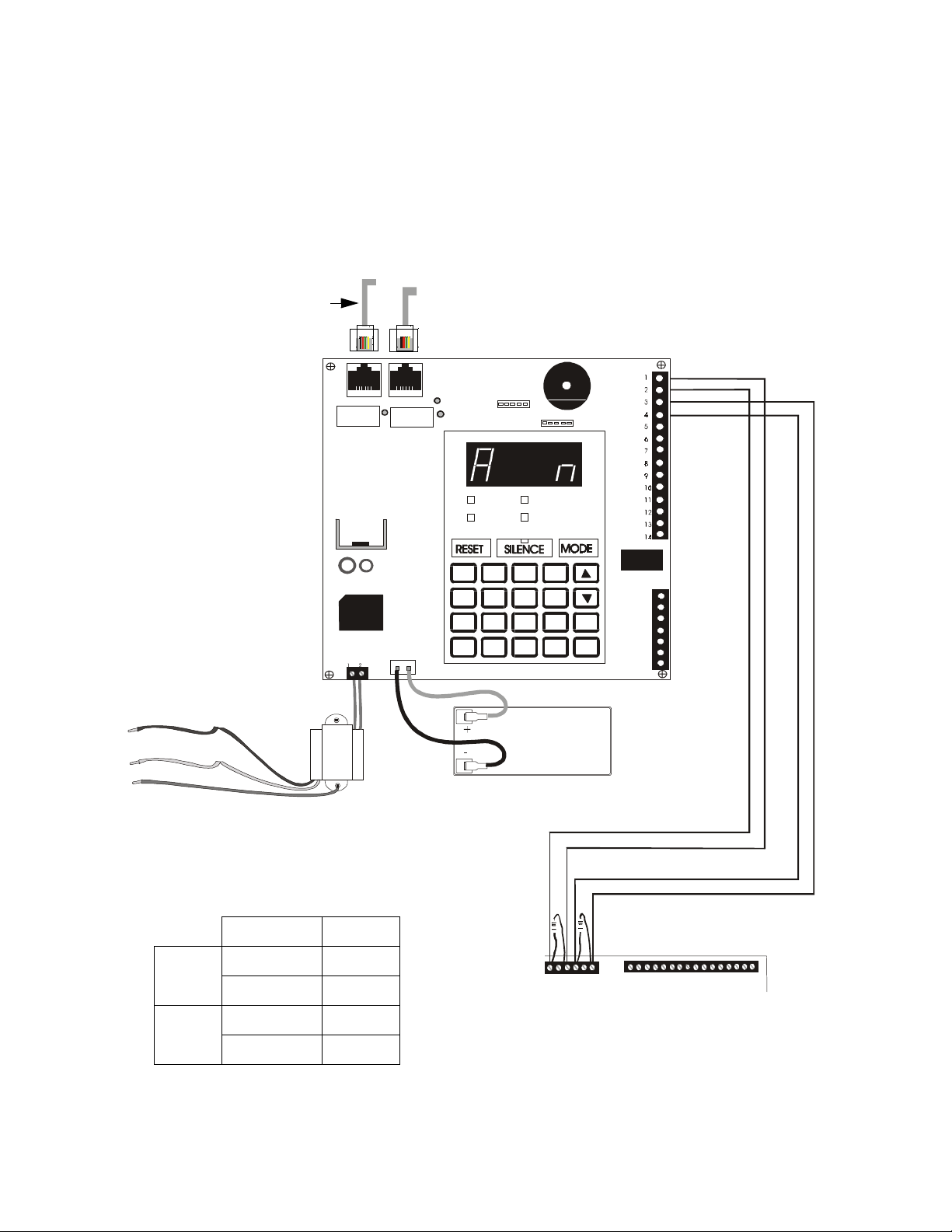
NFPA 72 Signaling Systems for Central Station Service
NFPA 72 Signaling Systems for Central Station Service
(Protecte d Premises Unit) and Remote Station Fire Ala rm Sys te m ( Protected Pr em is es Unit)
NOTI•FIRE 911 AC D ACT* - for connection to a Central Station Receiver or Protected
Premises Receiving Unit. This unit must be installed as illustrated below. For
additional information on the 911AC, refer to document 74-06200-005.
All connections between the FACP and 911AC must be in conduit, less than 20 ft
(609.6cm) in length in the same room. If the NOTI•FIRE 911AC is not mounted in the
PDRP-1002/PDRP-1002E backbox all connections must be in conduit, less than 20 ft.
(609.6 cm) in length in the same room.
*This application using the NOTI•FIRE 91 1AC is not FM approved.
Note: For 911AC
• The Maximum standby load shall be 125 mA.
• The Standby by Battery Requirement: 24VDC, 7Amp-Hour-Max.
• The PDRP-1002/PDRP-1002E is not suitabl e fo r transm ission of a supe rvi sory sig na l to the DACT.
Note: The PDRP-1002/
PDRP-1002E is not
suitable for transmission
of a supervisory signal to
th e DACT
To AC
Power
Alarm
Appendix C: NFPA Standard-Specific Requirements
NOTE on STD DACT:
Place jumper over pins 2 and 3,
marked DACT, when employing a
DACT. This di rect s the c o ntr ol pane l
1
2
3
4
5
6
7
8
9
10
11
12
1
12VAC, 20VA, 60Hz or +24VDC
2
12VAC, 20VA, 60Hz or -24VDC
3
(Refer to manual)
BATTERY -
4
BATTERY +
5
INITIATING A1 -
6
INITIATING A2 -
7
INITIATING B1 +
8
INITIATING B2 +
9
SUPE R V IS O R Y H I
10
SUPE R V IS O R Y LO
11
TROUBLE RELAY NC
12
TROUBLE RELAY COM
13
TROUBLE RELAY NO
14
ALARM RELAY NC
15
ALARM RELAY COM
16
ALARM RELAY NO
17
Digital Alarm Co mmunicator Transmitter Listed for Central Station or Remote Station Service.
Slide Cover Back to Access Programming Jack and Relays
- 12 VDC Sealed
R echa rge able
+ Battery
+
-
PS1270
12Volt
7AH Battery
Alternate RJ31X
Primary RJ31X
Telco J a c k
Telco J a c k
to transmit all trouble conditions
except AC LOSS.
To Central Station
JP-1
Motherboard 911AC
Alarm
normally open
contacts
Trouble
normally open
RP911AC.CD
contacts
Figure 13 NFPA 72 Signaling Systems for Central Station Service
TB3-1 6 and 7
TB3-3 8 and 9
TB3-4 10
TB3-6 11
STDDACT
The PDRP-1002 PN 51135: A 03/11/99 37
Page 38
Appendix C: NFPA Standard-Specific Requirements
Using the MS-5012 as a DACT
1) Reference the MS-5012 manual for additional information.
2) Program the MS-5012 for slave applications.
3) The PDRP-1002/PDRP-1002E is not suitable for transmission of a supervisory
signal to the DACT.
Secondary
Modular Cable
P/N MCBL-6
Phone Line
Primary
Phone Line
NFPA 72 Signaling Systems for Central Station Service
120 VAC
HOT
Neutral
Ground
Yellow
Yellow
Black
White
Green
AC Wiring for DACT/FACP must be
connected to the s a me circuit.
Red
Black
MS-5012
J2
AC POWER
ALARM
1
23
5
4
7
8
A
OB
TROUBLE
SUPERVISORY
6
9
12VDC
Battery
2-7AH
Alarm
TB2
J3
Trouble
F
E
1st
D
EVENT
ENTER
C
STORE
TB3
Motherboard MS-5012
TB3-1 TB2-2
Alarm
TB3-3 TB2-1
1 2 3 4 5 6
TB3
MS5012X2.CDR
PDRP-1002/PDRP-1002E
Trouble
38 The PDRP-1002 PN 51135:A 03/11 / 99
TB3-4 TB2-4
TB3-6 TB2-3
Figure 14 Using the MS-5012 as a DACT
Page 39

NFPA 72 Auxiliary Fire Alarm System
NFPA 72 Auxiliary Fire Alarm System
All connections are power limited and supervised. This application is not suitable for
separate transmission of sprinkler supervisory or trouble conditions.
Note: Maximum loop resistan ce allowed for wiri ng from control panel to Municipa l Bo x is 3 ohm s.
Appendix C: NFPA Standard-Specific Requirements
4XTB
4XTM (NOTIFIER)
Transmitter Module
(activated polarities
shown)
+
Municipal Box Circuit
-
-
+
6
7
Figure 15 NFPA 72 Auxiliary Fire Alarm System
FIRE
AUXPROSS.CDR
Gamewell
Model M34-56
Local Energy
Municipal Box
The PDRP-1002 PN 51135: A 03/11/99 39
Page 40

Appendix C: NFPA Standard-Specific Requirements
NFPA 72 Remote Station Fire Alarm System
Intended for connection to a polarity reversal circuit of a remote station receiving unit
having compatible ratings. All connections are power limited and supervised with the
exception of the reverse polarity loop. Supervision of the loop is the responsibility of
the receiver.
NFPA 72 Remote Station Fire Alarm System
DRY
SUPPLEMENTARY
CONTACTS,
RATED
3A, 120 VAC
RESISTIVE
3A, 30 VDC
RESISTIVE
REMOTE STATION
MASTER BOARD
(RSM-9)
N.C.2
N.O.2
POLE 2
N.C.1
N.O.1
POLE 1
A.C. CKT BREAKER
120 VAC
1.2 AMPS
9
10
SIGNALING
11
RELAY FOR
BELLS AND
12
1
DRY
13
CONTACTS
14
CONTROL CARD
(RSC)
CIRCUIT SIDE
ZONE CARD(RSZ)
CIRCUIT SIDE
OPTIONAL ZONE CARD
(RSZ) CIRCUIT SIDE
OPTIONAL ZONE CARD
(RSZ) CIRCUIT SIDE
OPTIONAL ZONE CARD
(RSZ) CIRCUIT SIDE
OPTIONAL ZONE CARD
(RSZ) CIRCUIT SIDE
OPTIONAL ZONE CARD
(RSZ) CIRCUIT SIDE
OPTIONAL ZONE CARD
(RSZ) CIRCUIT SIDE
OPTIONAL ZONE CARD
(RSZ) CIRCUIT SIDE
OPTIONAL ZONE CARD
(RSZ) CIRCUIT SIDE
K | | | | | | | | | | K
PRESS TO
RESET
BATTERY
CKT FUSE
8 AG
5 A
125 V
FILTER
CAP
--
-K
--
--
--
K
2
8
7
6
5
BATT
CONN
4
3
2
2
1
1
2
1
2
2
1
1
2
1
2
2
1
1
2
1
2
1
2
2
1
1
1
GROUNDING
TERMINAL
N/C
BELL
or
HORN
}
}
}
}
}
}
}
120 VAC 1.2 A
}
50-60 Hz
INPUT
+
-
H
10 K
ELR
ALARM
SIGNAL
INPUT 3
ALARM
SIGNAL
INPUT 4
ALARM
SIGNAL
INPUT 5
ALARM
SIGNAL
INPUT 6
ALARM
SIGNAL
INPUT 7
ALARM
SIGNAL
INPUT 8
ALARM
SIGNAL
INPUT 9
Fire•Lite
RS82-9
Remote Station
Receiver
UL listed
-
+
-
+
Recommended Types:
ELPOWER EP 1250C
+
POWER SONIC PS 1245
Power Transformer
1
Remote Alarm
2
3
Remote Trouble
4
POWER SONIC PS 1260
POWER SONIC PS 1265
YUASA NPG-12
or equivalent
-
MAXIMUM BATTERY SIZE
6.0 X 2.6 X 4.1 in. (15.24 x 6.6 x10.41
4XTM (NOTIFIER)
Transmitter Module
(activated polarities shown)
REMPROSS.CDR
Figure 16 NFPA 72 Remote Station Fire Alarm System
40 The PDRP-1002 PN 51135:A 03/11 / 99
Page 41

NFPA 72 Remote Station Fire Alarm System
Appendix C: NFPA Standard-Specific Requirements
Troubleshooting Table
SYMPTOM PROBLEM SOLUTION
1. Check TB2 for proper connections. (TB3 for
4XB panels)
2. Remove all field wiring and install dummy ELR
at output circuit. Check for supervisory voltage
across it. (Normal -2.3 V). If problem persists,
replace circuit board.
3. Removed dummy ELR, reconnect field wiring
and measure voltage across output; (trouble -5V,
short OV).
4. Check for ELR at last device.
5. Check field wiring.
1. Check TB4 for proper connections.
2. Remove field wiring for zone in trouble and
install dummy ELR (4.7K for 24V; 2.2K for 12V).
If problem persists, replace circuit board.
3. Check for ELR at last device.
4. Check field wiring.
Check battery connections
1. Remove batteries, check voltage across charger
output (17 to 19V for 24V; 8-10V for 12V),
otherwise replace circuit board.
2. Reconnect batteries, measure battery voltage at
battery terminals. If voltage is less than 85% of
rated voltage, allow them to charge for 48 hours.
3. If problem persists, replace batteries.
1. Remove field wiring from main panel and
optional module(s) (if installed). Install dummy
ELR (4.7K for 24V; 2.2K for 12V).
2. Remove both battery leads.
3. If trouble clears, connect one circuit at a time to
pinpoint the problem.
4. If trouble doesn’t clear, replace circuit board.
Install optional module(s) or replace jumper if
module(s) is not used.
1. Install dummy load if Municipal Box option
isn’t used.
2. Check Municipal Box wiring.
Remove field wiring and install ELR. If trouble
clears, look for faulty or incorrectly wired devices.
Cut associated jumper OPT1 or OPT2.
1. Make sure module is properly installed.
2. Move disable switch SW1 on 4XZM to the left.
1. Make sure that 4XLM module is installed on J7
and J8.
2. Check field wiring.
Hit system reset.
Check incoming power (TB5 ). (TB1 for 4XB
panels)
AC Power LED on
AC Power LED off
Circuit trouble LED on Noti fication appliance circuit trouble
Any of the right column
yellow LEDs flashing
System trouble LED on
Any of the right column red LEDs on Short on initiating circuit wiring
Disconnecting Municipal Box switch on 4XTM
does not create a trouble
4XZM: associated LED does not activate for alarm,
trouble or supervisory conditions
RZA-4X piezo doesn’t sound for alarm, trouble or
supervisory conditions
Micro Fail yellow LED on Microprocessor damaged. Replace circuit board.
All RZA-4X LEDs stay on
System trouble LED on
Micro Fail yellow LED on Microprocessor damaged Replace circuit board.
Any of the right column
yellow LEDs steady on
Power trouble LED on
Yellow LED on 4XTM on 4XTM 1. Move Municipal Box disconnect switch SW1 up
Initiating zone open circuit trouble
Zone Disable Check installation manual.
Missing or
Disconnected
Battery trouble
Batt yellow LED
on
Ground fault trouble
Earth yellow LED on
OPT1, OPT2 jumper cut
Municipal Box open circuit
Jumper for optional modules isn’t
cut.
Optional module trouble
4XLM
Power wasn’t removed prior to
installation.
Loss of main power
Damaged circuit breaker Replace circuit board.
Low or damage
battery
Table 8 Trouble Shooting Table
The PDRP-1002 PN 51135: A 03/11/99 41
Page 42

Appendix C: NFPA Standard-Specific Requirements
NFPA 72 Remote Station Fire Alarm System
Notes
42 The PDRP-1002 PN 51135:A 03/11 / 99
Page 43

NFPA 72 Remote Station Fire Alarm System
Appendix C: NFPA Standard-Specific Requirements
Notes
The PDRP-1002 PN 51135: A 03/11/99 43
Page 44

Appendix C: NFPA Standard-Specific Requirements
Limited Warranty
NFPA 72 Remote Station Fire Alarm System
System Sensor
®
warrants its products to be free from defects in materials and
workmanship for eighteen ( 18) months from the date of manufacture, under normal
use and serv ice. Products are date stam ped at time of manufacture. The sole and
exclusive obligation of
System Sensor
®
is to repair or r eplace, at is option, free of
charge for part s and labor, any part which is d efective in materials or workmansh ip
under normal use and service. For products not under
System Sensor
manufacturing date-stamp c ontrol, the warranty is ei ghteen (18) months from date of
original purcha se by
System Sensor
®
distributor unle ss the installation in structions
or catalog sets forth a s horter period, in which case the shorter per iod shall apply.
This warranty is void if the product is altered, repa ired or serviced by anyone other
System Sensor
than
®
or its authorized di stributors or if there is a failure to maintain
the products and systems in which they operate in proper and workable manner. In
®
case of defect, phone System Sensor
Repair Department, RA #_____________,
3825 Ohio Avenue, St. Charles, IL 60174. Please include a note describing the
malfunction and suspected cause of failure.
This writing con stitutes the only warranty made by
its products.
System Sensor
®
does not represent that its produc ts will prevent any
System Sensor
®
with respect to
loss by fire or other wise, or th at its p ro duc ts will in all cases provide the pr ot ec tion for
which they are installe d or intended. Buyer acknowledges t hat
System Sensor
®
is
not an insurer and as sumes no risk for loss or dam ages or the cost of a ny inconvenience, transportation, damage, misuse, abuse, accident or similar incident.
SYSTEM SENSOR
®
GIVES NO WARRANTY, EXPRESSED OR IMPLIED, OF
MERCHANTABILITY, FITNESS FOR ANY PARTICULAR PURPOSE, OR
OTHERWISE WHICH EXTEND BEYOND THE DESCRIPTION ON THE FACE
HEREOF. UNDER NO CIRCUMSTANCES SHALL
SYSTEM SENSOR
®
BE LIABLE
FOR ANY LOSS OF OR DAMAGE TO PROPERTY, DIRECT, INCIDENTAL OR
CONSEQUENTIAL, ARISING OUT OF THE USE OF, OR INABILITY TO USE
SYSTEM SENSOR
®
PRODUCTS. FURTHERMORE,
SYSTEM SENSOR
®
SHALL
NOT BE LIABLE FOR ANY PERSONAL INJURY OR DEATH WHICH MAY ARISE IN
THE COURSE OF, OR AS A RESULT OF, PERSONAL, COMMERCIAL OR
INDUSTRIAL USE OF ITS PRODUCTS.
®
This warranty replaces all previous warranties and is the only warranty made by
System Sensor
®
. No increase or alteration, written or verbal, of the obligation of this
warranty is authorized.
System Sensor
3825 Ohio Avenue, St. Charles, IL 60174
1-800-SENSOR2 Fax: 630-377-6495
44 The PDRP-1002 PN 51135:A 03/11 / 99
 Loading...