

Page 1
INSTALLATION AND MAINTENANCE INSTRUCTIONS
3825 Ohio Avenue, St. Charles, Illinois 60174
1-800-SENSOR2, FAX: 630-377-6495
M502M Interface Module
Specifications
Normal Operating Voltage: 15 to 32 VDC
Maximum Current Draw: 5.1mA (LED on)
Average Operating Current: 300µA, 1 communication and 1 LED flash every 5 seconds, 3.9k eol
EOL Resistance: 3.9K Ohms
Maximum IDC wiring resistance: 25 Ohms
IDC Supply Voltage (between Terminals T10 and T11)
Regulated DC Voltage: 24 VDC power limited
Ripple Voltage: 0.1 Volts RMS maximum
Current: 90mA per module
Temperature Range: 32˚F to 120˚F (0˚C to 49˚C)
Humidity: 10% to 93% Non-condensing
Dimensions: 4
Accessories: SMB500 Electrical Box
Before Installing
This information is included as a quick reference installation
guide. Refer to the control panel installation manual for detailed
system information. If the modules will be installed in an existing
operational system, inform the operator and local authority that
the system will be temporarily out of service. Disconnect power to
the control panel before installing the modules.
NOTICE: This manual should be left with the owner/user of
this equipment.
General Description
The M502M Interface Module is intended for use in intelligent,
two-wire systems, where the individual address of each module
is selected using the built-in rotary decade switches. This module
allows intelligent panels to interface and monitor two-wire conventional smoke detectors. It transmits the status (normal, open,
or alarm) of one full zone of conventional detectors back to the
control panel. All two-wire detectors being monitored must be UL
compatible with this module. The M502M has a panel controlled
LED indicator.
Compatibility Requirements
To ensure proper operation, these modules shall be connected to
listed compatible system control panels only.
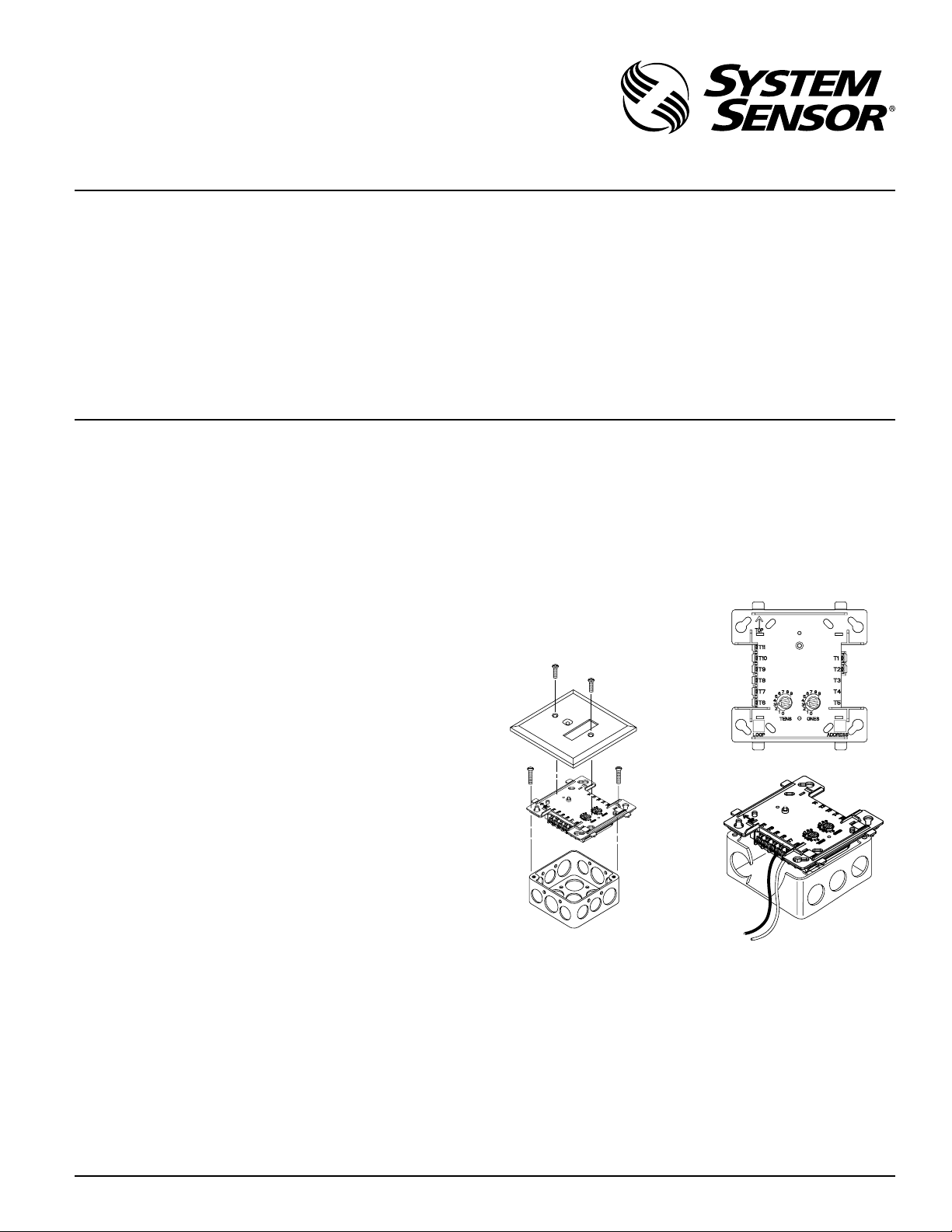
Mounting
The M502M mounts directly to 4˝ square electrical boxes (see Figure
2A). The box must have a minimum depth of 2
electrical boxes (SMB500) are available from System Sensor.
1
⁄2˝ H x 4˝ W x 11⁄4˝ D (Mounts to a 4˝ square by 21⁄8˝ deep box.)
Wiring
NOTE: All wiring must conform to applicable local codes, ordinances, and regulations. This module is intended for power-limited wiring only.
1. Install module wiring in accordance with the job drawings
and appropriate wiring diagrams.
2. Set the address on the module per job drawings.
3. Secure module to electrical box (supplied by installer), as
shown in Figure 2A.
Figure 1. Controls and indicators:
Figure 2A. Module mounting with barrier:
Figure 2B:
1
⁄8˝. Surface mounted
C0449-03
I56-3854-001
www.systemsensor.com
C0218-03
C0450-03
Compatible Two-wire System Sensor Smoke Detectors for Use with M502M with Zone Identifier A:
Detector Compatibility Detector Base Base Max
Model ID Type Model Identifier Detectors
1451 A Ionization B401/B A 20
2451 A Photoelectric B401/B A 20
2451TH A Photoelectric with Thermal B401/B A 20
1400 A Ionization N/A — 20
2400 A Photoelectric N/A — 20
2400TH A Photoelectric with Thermal N/A — 20
1100 A Ionization N/A — 20
1151 A Ionization B110LP/B401 A 20
2100 A Photoelectric N/A — 20
2100T A Photoelectric with Thermal N/A — 20
2151 A Photoelectric B110LP/B401 A 20
*Used in combination with MTL isolator model MTL3043.
SS-460-003 1 I56-3854-001
Page 2
(+)
(–)
(+)
(–)
(+)
(–)
+
–
+
–
LISTED BATTERY-BACKUP SWITCHED
REGUALTED DC POWER SUPPLY
POWER TO THE INTERFACE MODULE
MUST BE EXTERNALLY SWITCED TO
RESET THE DETECTORS. AN M500R RELAY
CONTROL MODULE CAN BE USED TO
SWITCH POWER FROM A STANDARD
POWER SUPPLY - SEE FIGURE 5.
OPTIONAL BRANCH CIRCUIT
TO NEXT INTERFACE MODULE.
MODULE SUPERVISES SUPPLY
VOLTAGE AND DETECTOR LOOP.
(+)
(–)
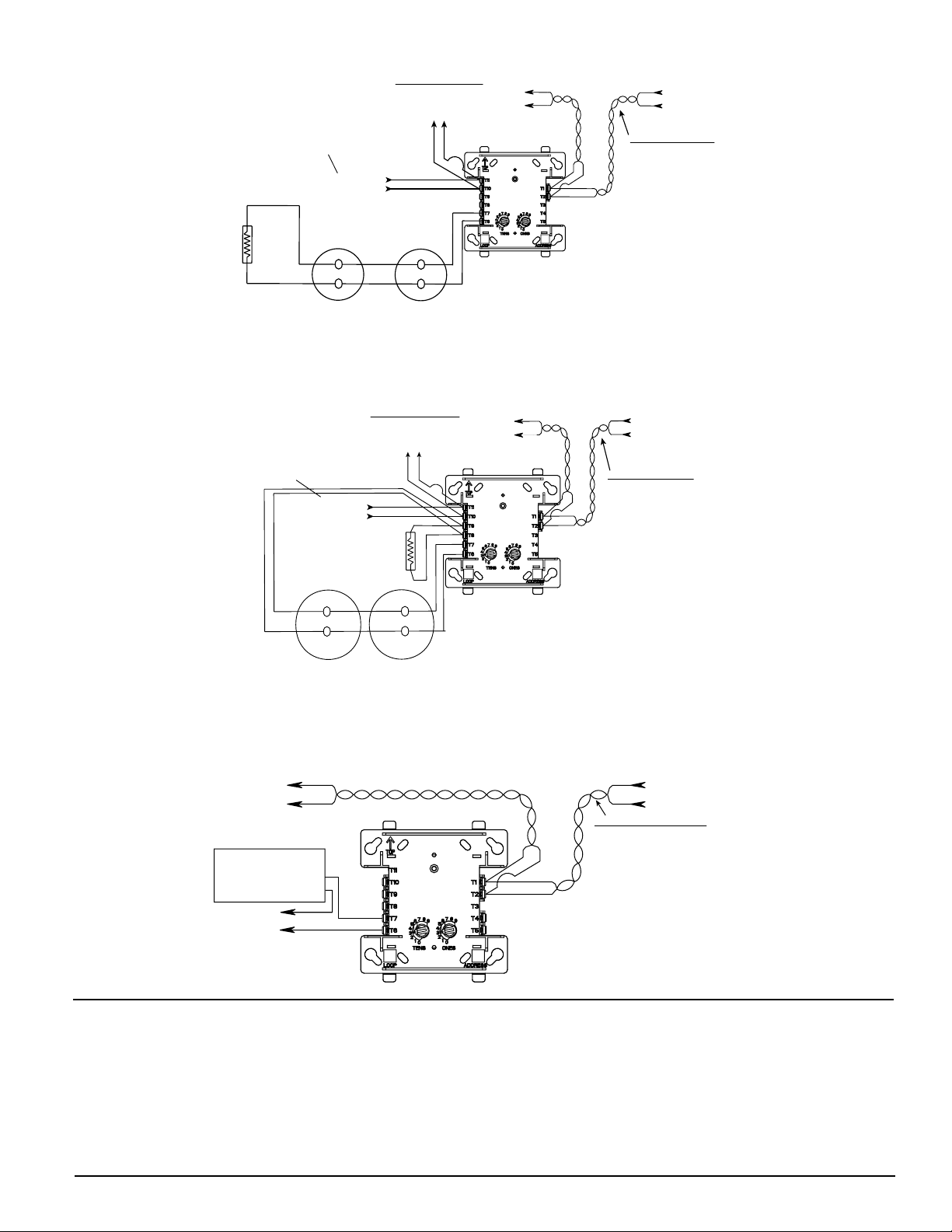
TERMINAL WIRING MUST BE POWER LIMITED.
DO NOT MIX FIRE ALARM INITIATING, SUPERVISORY,
OR SECURITY DEVICES ON THE SAME MODULE.
TO NEXT
DEVICE
INTERFACE
MODULE
SIGNAL LINE CIRCUIT (SLC)
32 VDC MAX.
TWISTED PAIR
IS RECOMMENDED
CONNECT MODULES TO LISTED
COMPATIBLE CONTROL PANELS ONLY.
FROM PANEL OR
PREVIOUS DEVICE
3.9K EOL
RESISTOR
(INCLUDED)
A2143-10
DO NOT LOOP WIRE UNDER TERMINALS. BREAK ALL WIRE
RUN TO PROVIDE SUPERVISION OF CONNECTIONS.
DETECTORS MUST BE UL LISTED COMPATIBLE WITH
MODULE. INSTALL DETECTORS PER MANUFACTURER’S
INSTALLATION INSTRUCTIONS
*NOTE: ANY FAULT IN THE POWER SUPPLY IS LIMITED TO THAT ZONE AND DOES NOT RESULT IN A FAULT IN A SEPARATE ZONE.
(+)
(–)
(+)
(–)
(+)
(–)
+
–
+
–
(+)
(–)
LISTED BATTERY-BACKUP
SWITCHED REGUALTED
DC POWER SUPPLY
POWER TO THE INTERFACE MODULE
MUST BE EXTERNALLY SWITCED TO
RESET THE DETECTORS. AN M500R RELAY
CONTROL MODULE CAN BE USED TO
SWITCH POWER FROM A STANDARD
POWER SUPPLY - SEE FIGURE 5.
OPTIONAL BRANCH CIRCUIT
TO NEXT INTERFACE MODULE.
MODULE SUPERVISES SUPPLY
VOLTAGE AND DETECTOR LOOP.
TERMINAL WIRING MUST BE POWER LIMITED.
DO NOT MIX FIRE ALARM INITIATING, SUPERVISORY,
OR SECURITY DEVICES ON THE SAME MODULE.
3.9K EOL RESISTOR
REQUIRED AT TERMINALS
8 & 9 (INCLUDED) A2143-10
DO NOT LOOP WIRE UNDER TERMINALS. BREAK ALL WIRE
RUN TO PROVIDE SUPERVISION OF CONNECTIONS.
DETECTORS MUST BE UL LISTED COMPATIBLE WITH
MODULE. INSTALL DETECTORS PER MANUFACTURER’S
INSTALLATION INSTRUCTIONS
INTERFACE
MODULE
TO NEXT
DEVICE
SIGNAL LINE CIRCUIT (SLC)
32 VDC MAX.
TWISTED PAIR
IS RECOMMENDED
CONNECT MODULES TO LISTED
COMPATIBLE CONTROL PANELS ONLY.
FROM PANEL OR
PREVIOUS DEVICE
*NOTE: ANY FAULT IN THE POWER SUPPLY IS LIMITED TO THAT ZONE AND DOES NOT RESULT IN A FAULT IN A SEPARATE ZONE.
(–)
(–)
Figure 3. Interface two-wire conventional detectors, NFPA Style B:
Figure 4. Interface two-wire conventional detectors, NFPA Style D:
C0921-06
Figure 5. Relay control module used to disconnect a power supply:
TO NEXT
DEVICE
POWER LIMITED DC
POWER SUPPLY,
LISTED FOR FIRE
PROTECTION WITH
Syst em Senso r war rant s its enclosed product to be f ree f rom defects in ma terials and workmanship u nder nor mal use a nd servi ce for a p eriod of three yea rs
from date of man ufacture. System Sensor makes no other express warranty
for the enclos ed product. No agent, repre sentati ve, d ealer, or employee of the
Company has the authority to increase or alter the obligations or lim itations
of thi s Warrant y. The Company’s o bligati on of thi s Warrant y shall b e limited
to the repla cement of any p art of the prod uct which is found to be defective
in materi als or workmans hip under norma l use and service d uring the t hree
year pe riod commencin g with the date of manufact ure. After phon ing System
Sensor’s toll free nu mber 800 -SENSOR2 (736-7672) for a Return Authoriza tion
number, se nd defec tive units postage prepaid to: System S ensor, Retu rns
SS-460-003 2 I56-3854-001
© 2008 System Sensor
BATTERY BACKUP
(–)
(+)
(+)
(+)
(–)
RELAY CONTROL
MODULE
Three-Year Limited Warranty
C0922-06
FROM PANEL OR
PREVIOUS DEVICE
(+)
SIGNAL LINE CIRCUIT (SLC)
32 VDC MAX.
TWISTED PAIR
IS RECOMMENDED
(–)
(+)
*NOTE: ANY FAULT IN THE POWER SUPPLY IS LIMITED TO THAT
ZONE AND DOES NOT RESULT IN A FAULT IN A SEPARATE ZONE.
CONNECT MODULES TO LISTED
COMPATIBLE CONTROL PANELS ONLY.
C0923-02
Department, RA #____ ______, 3825 Ohio Avenue, St. Char les, IL 60174. Pleas e
include a note descri bing the mal function and suspected cause of failu re.
The Compa ny sha ll not b e obligated to repl ace units which a re found to be
defective because of d amage, unre asonable use, modificati ons, or a lterations
occurring after the date of ma nufactu re. In no case shall the Company be
liable for any conseque ntial or incid ental damages for b reac h of th is or any
other Warran ty, expre ssed o r impl ied whatso ever, even if t he loss o r dama ge
is caused by t he Comp any’s ne gligence or fa ult. So me states do n ot allow th e
excl usion or limitation o f inci dental or consequen tial damages, so the above
limitation or exclusion m ay no t apply t o you . This Warra nty gives you spec ific
legal ri ghts, and you may als o have othe r rig hts which vary from stat e to state.
 Loading...