

Page 1
INSTALLATION AND MAINTENANCE INSTRUCTIONS
FAULT ISOLATOR MODULE
M500X FAULT ISOLATOR MODULE
SPECIFICATIONS
Normal Operating Voltage: 15 - 32 VDC
Stand-by Current: 450 µA (not isolating)
Maximum Current Draw: 17mA (device in isolation)
Temperature Range: 32°F to 120°F (0°C to 49 °C)
Humidity: 10 to 93% Non-condensing
Dimensions: 41/2" H × 4" W × 1/4" D (Mounts to a 4" square by 21/8" deep box)
I56-3629-018
3825 Ohio Avenue, St. Charles, Illinois 60174
1-800-SENSOR2, FAX: 630-377-6495
www.systemsensor.com
BEFORE INSTALLING
This information is included as a quick reference installation guide. Refer to
the control panel installation manual for detailed system information. If the
modules will be installed in an existing operational system, inform the operator and local authority that the system will be temporarily out of service. Disconnect power to the control panel before installing the modules.
NOTICE: This manual should be left with the owner/user of this equipment.
GENERAL DESCRIPTION
M500X Fault Isolator Modules enable part of the communications loop to continue operating when a short circuit occurs on it. An LED indicator blinks in
the normal condition and turns on during a short circuit condition. The module will automatically restore the entire communications loop to the normal
condition when the short circuit is removed.
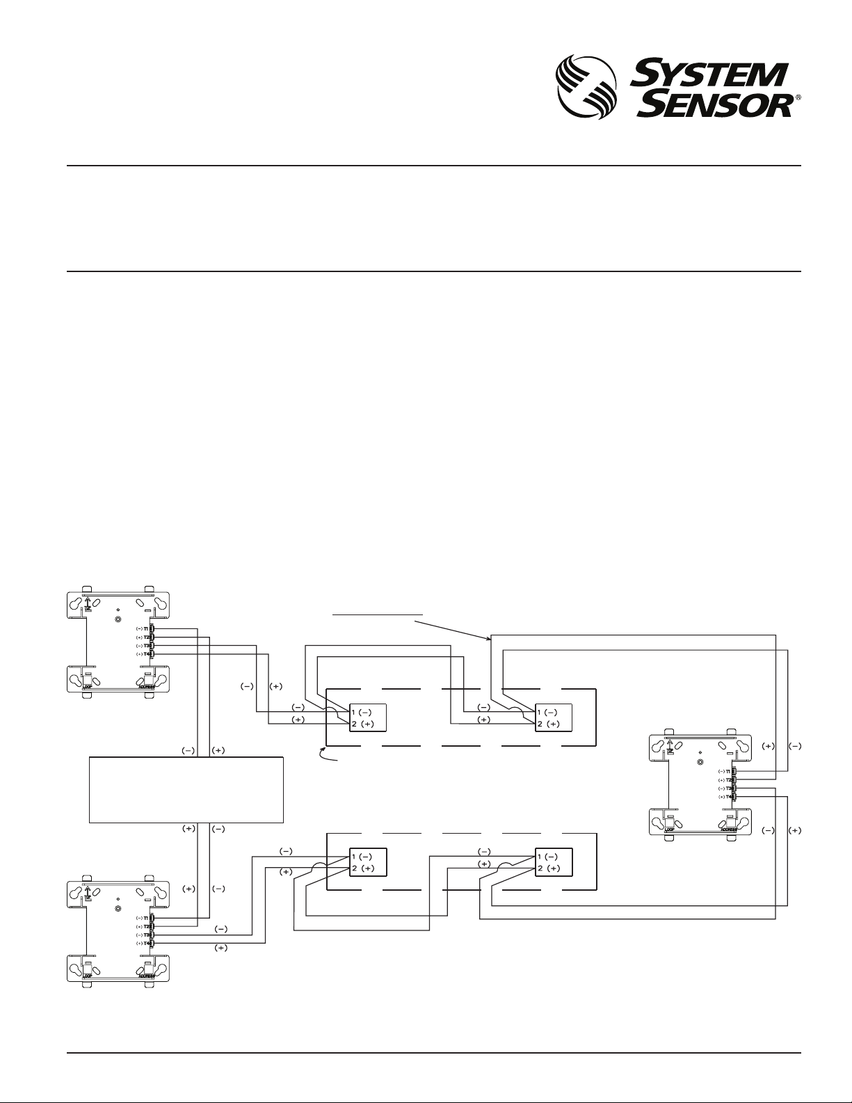
FIGURE 1. FAULT ISOLATOR MODULE WIRING:
SIGNAL LINE CIRCUIT (SLC)
32 VDC MAX.
COMPATIBILITY REQUIREMENTS
To ensure proper operation, these modules shall be connected to listed compatible system control panels only.
NOTE: The number of devices that may be installed between fault isolator
modules will vary based on the types of devices being isolated. Contact the
fire alarm control panel manufacturer for the isolator load ratings of individual devices.
MOUNTING
M500X modules mount directly to 4˝ square electrical boxes. The box must
have a minimum depth of 21/8".
WIRING
NOTE: All wiring must conform to applicable local codes, ordinances and
regulations.
1. Install module wiring in accordance with the job drawings and the
wiring diagram in Figure 1.
2. Secure module to electrical box (supplied by installer).
3. Terminal wire gage: 12-18 AWG.
ALL WIRING SHOWN IS SUPERVISED
FAULT ISOLATOR MODULE
GROUPS OF DEVICES ARE SEPARATED BY FAULT ISOLATOR
MODULES. ANY COMBINATION OF COMPATIBLE, LISTED
UL LISTED COMPATIBLE
CONTROL PANEL
FAULT ISOLATOR MODULE
DEVICES MAY BE MIXED WITHIN A GROUP.
A PAIR OF FA ULT ISOLATOR MODULES WILL DISCONNECT A
GROUP OF DEVICES IF A SHORT CIRCUIT OCCURS ON THE
SIGNALING LINE CIRCUIT WITHIN THAT GROUP.
C0774-04
SS-460-011 1 I56-3629-018
©2012 System Sensor
 Loading...