

Page 1
INSTALLATION AND MAINTENANCE INSTRUCTIONS
I56-3070-002
M500M-4-20
4-20mA Analog Input Module
SPECIFICATIONS
SLC
Normal Operating Voltage: 15 to 32 VDC
Maximum Current Draw: 9.3 mA (LED on)
Average Operating Current: 1 mA (LED flashing)
External Supply
Normal Operating Voltage: 24 VDC Nominal
Standby Current: 10 mA
Maximum Current: 510 mA
Initiating Device
Maximum Current: 500 mA
Temperature Range: –10˚C to 60˚C
Humidity: 10% to 95% Non-condensing
Dimensions: 41/2˝ H × 4˝ W × 11/4˝ D (Mounts to a 4˝ square by 21/8˝ deep box.)
Accessories: SMB500 Electrical Box
BEFORE INSTALLING
This information is included as a quick reference installation guide. Refer to
the control panel installation manual for detailed system information. If the
modules will be installed in an existing operational system, inform the operator and local authority that the system will be temporarily out of service. Disconnect power to the control panel before installing the modules.
NOTICE: This manual should be left with the owner/user of this equipment.
GENERAL DESCRIPTION
The M500M-4-20 4-20mA Analog Input Module is intended for use in intelligent, two-wire systems, where the individual address of each module is
selected using the built-in rotary switches. This module allows intelligent panels to interface and monitor two-wire or three-wire sensors, that produce a
4-20mA signal output. It transmits the status (normal, open, or alarm) of one
sensor back to the control panel. The M500M-4-20 has a panel controlled LED
indicator. Only one sensor can be connected to the M500M-4-20.
COMPATIBILITY REQUIREMENTS
To ensure proper operation, this module shall be connected to a listed compatible system control panel only.
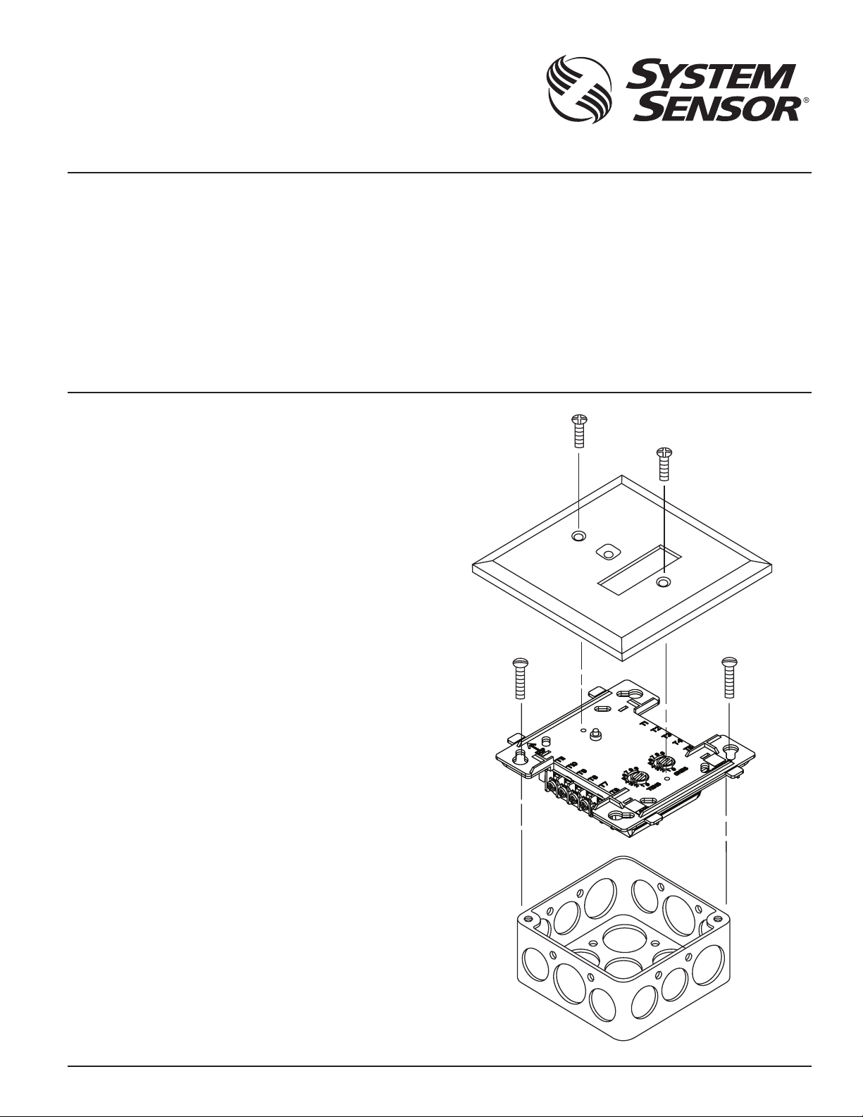
MOUNTING
The M500M-4-20 mounts directly to 4-inch square electrical boxes (see Figure
1). The box must have a minimum depth of 21/8 inches. Surface mounted
electrical boxes (SMB500) are available from System Sensor.
WIRING
NOTE: All wiring must conform to applicable local codes, ordinances, and
regulations. This module is intended for powerlimited wiring only.
1. Install module wiring in accordance with the job drawings and appropriate wiring diagrams.
2. Set the address on the module per job drawings.
3. Secure module to electrical box (supplied by installer), as shown in
Figure 1.
FIGURE 1. MODULE MOUNTING:
3825 Ohio Avenue, St. Charles, Illinois 60174
1-800-SENSOR2, FAX: 630-377-6495
www.systemsensor.com
C0959-00
SS-460-000 1 I56-3070-002
Page 2
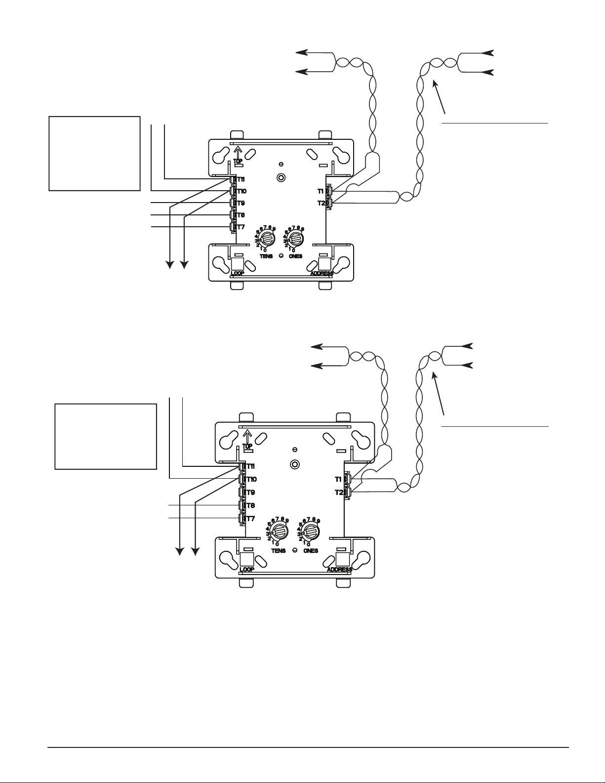
(+)
(–)
(+)
(–)
(+)
(–)
TERMINAL WIRING MUST
BE POWER LIMITED.
DO NOT LOOP WIRE UNDER TERMINALS.
BREAK ALL WIRE RUNS TO PROVIDE
SUPERVISION OF CONNECTIONS.
M500M-4-20
MODULE
TO NEXT
DEVICE
SIGNAL LINE CIRCUIT (SLC) 32
VDC MAX.
TWISTED PAIR
IS RECOMMENDED
FROM PANEL OR
PREVIOUS DEVICE
SLC WIRING
24 VDC POWER
LIMITED
( + ) ( - )
(–) SENSE
(+)
{
TO 4-20mA
2-WIRE DEVICE
24 VDC POWER SUPPLY
ISOLATED, REGULATED,
POWER LIMITED PER
NFPA 70, UL 864 LISTED
FOR FIRE PROTECTION
SIGNALING USE WITH
BATTERY BACKUP.
TO NEXT
MODULE
(+)
(–)
(+)
(–)
(+)
(–)
TERMINAL WIRING MUST
BE POWER LIMITED
TO NEXT
DEVICE
M500M-4-20
MODULE
SIGNAL LINE CIRCUIT (SLC)
32 VDC MAX.
TWISTED PAIR
IS RECOMMENDED
FROM PANEL OR
PREVIOUS DEVICE
SLC
WIRING
( - )
SENSE
( + )
{
TO 4-20mA
3-WIRE
DEVICE
DO NOT LOOP WIRE UNDER TERMINALS.
BREAK ALL WIRE RUNS TO PROVIDE
SUPERVISION OF CONNECTIONS.
24 VDC POWER
LIMITED
( + ) ( - )
24 VDC POWER
SUPPLY ISOLATED,
REGULATED, POWER
LIMITED PER NFPA 70,
UL 864 LISTED FOR
FIRE PROTECTION
SIGNALING USE WITH
BATTERY BACKUP.
TO NEXT
MODULE
FIGURE 2. 4-20 A MODULE 3-WIRE CONFIGURATION:
m
C1034-01
FIGURE 3. 4-20 A MODULE 2-WIRE CONFIGURATION:
m
C1035-01
SS-460-000 2 I56-3070-002
©2008 System Sensor
 Loading...