

Page 1
INSTALLATION AND MAINTENANCE INSTRUCTIONS
M500DMR MULTIPLE MODULE
WITH TWO MONITOR INPUTS
AND TWO RELAY OUTPUTS
Specifications
Normal Operating Voltage:
Maximum Communication line series wiring resistance:
Maximum Supervisory loop series wiring resistance (monitor input):
EOL Resistance (monitor input):
Supervisory Voltage (monitor input):
Standby Current for complete product:
Relay Contact Rating:
Operating Temperature Range:
Operating Humidity Range:
Dimensions:
Addressing :
Telephone: (029) 85387800 Fax: (029) 88332959
15 to 32 VDC
40 Ohms
1500 Ohms
47K Ohms
8.8 VDC
1000 μA
2 Amps @ 30 VDC ; 1.5A @ 25VAC
-5℃ to 50℃ (23℉to 122℉)
10% to 93% RH (non-condensing)
108mm (L) x 94mm (W) x 24mm (D)
Module base address = Relay #1 (R1)
28 Tuan Jie South Road, Xi’an National
Hi-tech Industrial Development Zone
Province of Shaanxi, 710075, China
Module base address +1 = Input #1 (I1)
Module base address +2 = Relay #2 (R2)- Can be disabled by DIP switch
(See figure 1A).
Module base address +3 = Input #2 (I2)- Can be disabled by DIP switch
(See figure 1A).
Principle
This information is included with the module as a quick reference installation guide. Refer to the control panel manufacturer’s installation manual
for more detailed system information. If this module will be connected to an existing operational fire detection system, inform the building occupant
or owner and local authority that the system will be temporarily out of service. Disconnect power from the communications loop before installing
this module.
General Description
The M500DMR multi input-output module is capable of replacing two Class B monitor modules and two individual relay control modules on an
intelligent fire alarm loop. Each monitor input is intended to interface between a fire alarm control panel and one or more devices. Each relay output
is intended for Form C switching applications which don’t require wiring supervision for the load circuit.
Each monitored input has its own red LED, which can be controlled by the control panel. Each relay output has its own red LED, which can be controlled
by the panel as well.
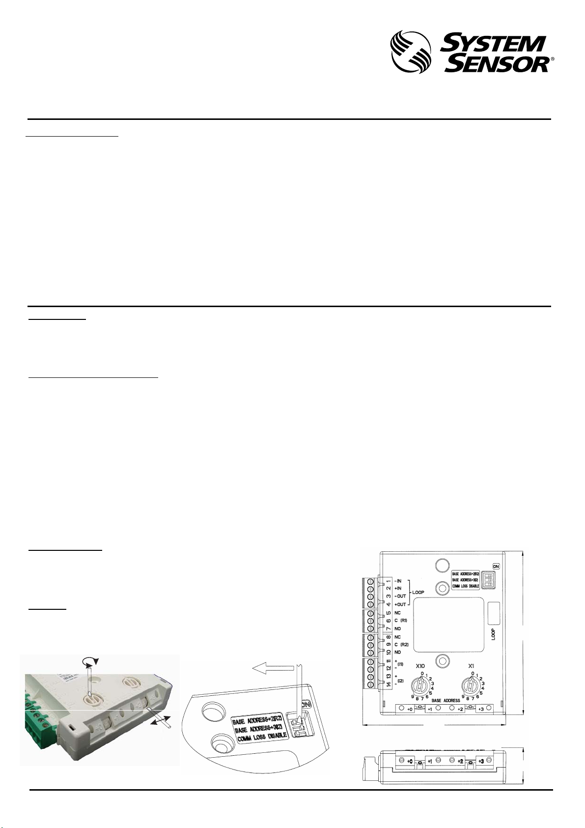
The module address is selected by means of rotary decade address switches (See Figure 1). These can be accessed either from the front or the top of
the module. A screwdriver should be used to rotate the wheels to select the desired address.
Each module can use up to four (4) addresses. The base address selected via the rotary address switches will be assigned to relay output #1 (R1) from 01
to 96. The module will automatically assign the next three addresses as appropriate to monitored input #1 (I1), relay output #2 (R2) and monitored
input #2 (I2).
If monitored relay output #2 (R2) and / or input #2 (I2) are not used, please switch the corresponding DIP switch to the ‘OFF’ position with a screwdriver
(See Figure 1A). These two addresses will then be free to be used for other devices on the loop.
This module can be used as an automatic switch which open circuits the line if the communication line voltage drops below 4 volts. If the line
voltage rises above 7 volts the product will detect the removal of the fault condition and restore power to the product automatically.
Installation
Note: Module M500DMR must only be connected to control panel using
compatible proprietary analogue addressable communication protocols
for monitoring and control.
The module can be mounted in two ways
Wiring
See
Figure 1. Rotary Decade Address Switches:
Figure 4 for wiring details.
(See Figure 3).
Figure 1A.
Figure 2. Module Dimensions:
108mm
94mm
24mm
1 I56-002-00C
Page 2
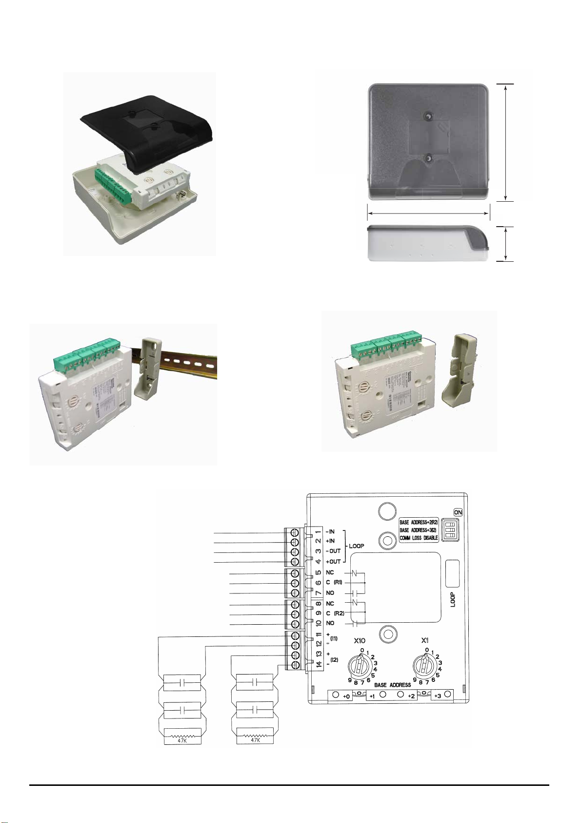
Figure 3. Module Mounting Methods:
Figure 3A. Surface Mount Box:
Figure 3B. DIN Rail Bracket:
Figure 4. M500DMR Multiple Module Wiring Diagram:
MODULE
BASE
COVER
Surface Mount Box Base is
affixed to mounting surface ,
and then the module and
cover are screwed onto the
base using the two screws
supplied.
TOP
BOTTOW
Push Module into adaptor
Bracket until it clips into
place.
Locate top clip over DIN rail
and rotate bottom down to clip
into place.
To Remove, lift up, then rotate
top away from the rail.
Surface Mounting Box Dimension:
139 mm
134 mm
40 mm
Figure 3C. Panel Mount Bracket:
Adaptor bracket is
mounted directly into
panel using 2 x M4
Pan head screws.
Module is pushed into
adaptor until it clips
into place.
LOOP IN LOOP IN +
LOOP OUT LOOP OUT +
NORMAL CLOSED 1
COMMON 1
NORMAL OPEN 1
NORMAL CLOSED 2
COMMON 2
NORMAL OPEN 2
2 I56-002-00C
Ver. C
 Loading...