

Page 1
M211E-RF
-20°C
+=
317 g
I 56- 4267- 001
mm
mm
Load -VE Load +VE
RADIO SYSTEM INPUT / OUTPUT MODULE
INSTALLATION INSTRUCTIONS
E N G L I S H
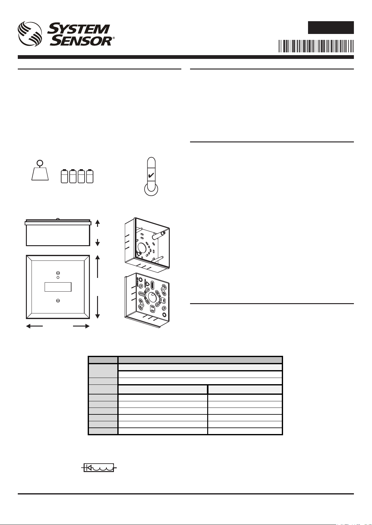
PARTS LIST
Module unit 1
SMB500 back box 1
Front cover 1
Batteries (Duracell Ultra 123 or Panasonic Industrial 123) 4
Back box xing screws and wall plugs 2
Module xing screws 2
3-pin terminal block 2
2-pin terminal block 1
47 k-ohm EOL resistor 2
18 k-ohm alarm resistor 1
Module installation instructions 1
SMB500 back box installation instructions 1
60°C
251 g
(66 g)
Figure 1: IO module + back box outside dimensions
58
125
125 mm
Table 1: Terminal Connections
DESCRIPTION
The M211E-RF radio input-output module is a battery operated RF
device designed for use with the M200G-RF radio gateway, running
on an addressable re system (using a compatible proprietary
communication protocol).
It is a dual module having separate input and output capability,
combined with a wireless RF transceiver and is supplied with a
wireless back box.
This device conforms to EN54-18 and EN54-25. It complies with the
requirements of 2014/53/EU for conformance with the RED directive.
SPECIFICATIONS
Supply Voltage: 3.3 V Direct Current max.
Standby Current: 122 µA@ 3V (typical in normal operating mode)
Red LED Current Max: 2 mA
Green LED Cur. Max: 5.5 mA
Re-Sync Time: 35s (max time to normal RF communication from
Batteries: 4 X Duracell Ultra123 or Panasonic Industrial 123
Battery Life: 4 years @ 25oC
Radio Frequency: 865-870 MHz. Channel width: 250kHz
RF Output Power: 14dBm (max)
Range: 500m (typ. in free air)
Relative Humidity: 5% to 95% (non-condensing)
Terminal Wire Size: 0.5 - 2.5 mm
IP Rating: IP20
Input Module
End-of-Line Resistor: 47K
Supervision Current: 34 µA typical
Output Module
End-of-Line Resistor: 47K
Supervision Current: 60 µA typical
Relay Contacts: 2 A @ 30 VDC (resistive load)
External Power Supply Unit
7.53
Voltage: 30V DC max. 8V DC min.
Supervision Fault Voltage: 7V DC typical
device power on)
2
INSTALLATION
This equipment and any associated work must be installed in
accordance with all relevant codes and regulations.
Figure 1 details the dimensions of the back box and cover.
Spacing between radio system devices must be a minimum of 1m
Table 1 shows the wiring conguration of the module.
TERMINAL
Figure 2: Diode Polarity
CONNECTION / FUNCTION
Input Module
Input -ve
1
Input +ve
2
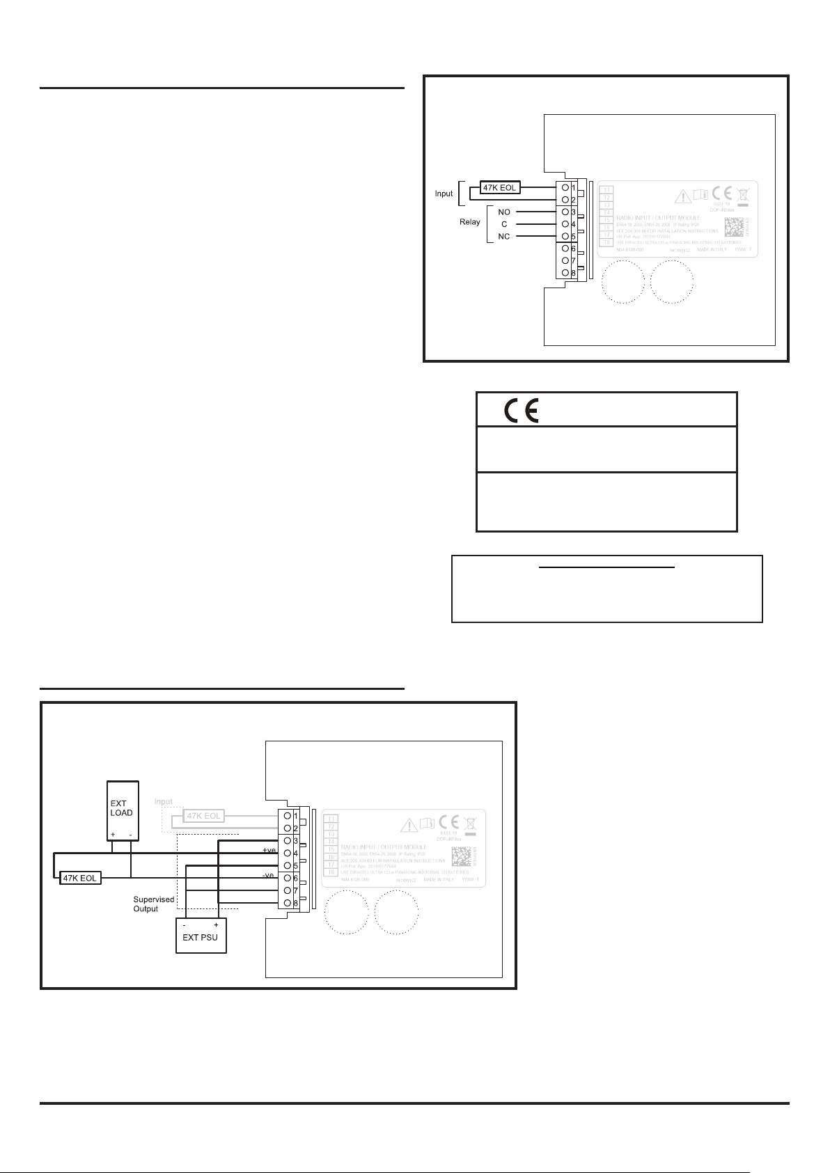
Output module (Supervised mode) Output module (Relay mode)
3 Connect to T8 Relay NO (normally open)
4 To load +ve Relay C (common)
5 Connect to T7 Relay NC (normally closed)
6 Supervision: connect to load -ve Not used
7 To ext PSU –ve Not used
8 To ext PSU +ve Not used
Input Module requires 47K EOL for normal operation.
Output Module requires 47K EOL at the load for normal
operation in supervised mode.
If the load is a low impedance (compared to the EOL) a
series diode should be added for correct load supervision
(see Figure 2 for diode polarity).
D200-309-00 I56-4267-001Pittway Tecnologica S.r.l. Via Caboto 19/3, 34147 TRIESTE, Italy
Page 2
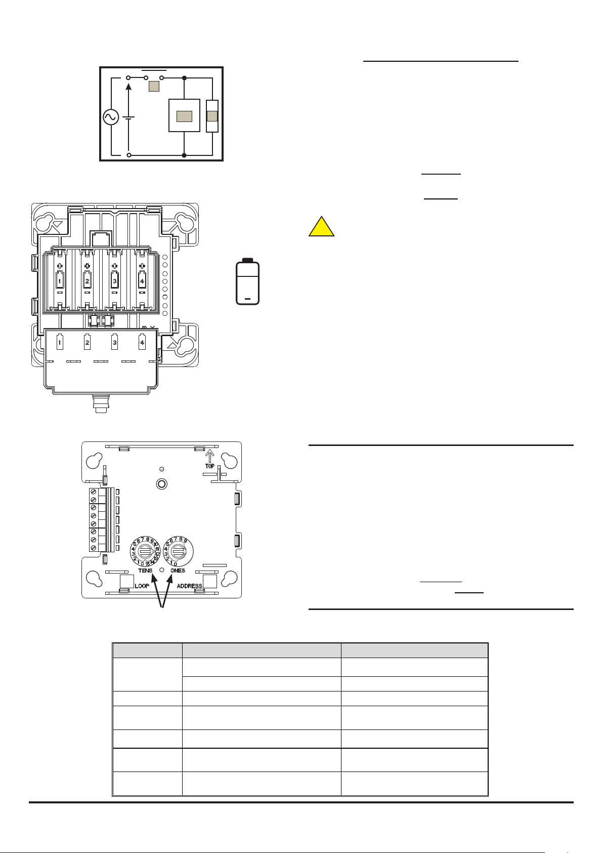
Figure 3: Switching Inductive Loads
(i)
+
(iii)
(ii)
Figure 4: Rear of Module with
Battery Compartment and Cover
+
NOTE POLARITY
Figure 5: Front of Module with Address Switches
1
2
3
4
5
6
7
8
ROTARY ADDRESS SWITCHES
Table 2: Module Status LEDs
WARNING: Switching Inductive Loads
See Figure 3. Inductive loads can cause switching surges, which may
damage the module relay contacts (i).
To protect the relay contacts, connect a suitable Transient Voltage
Suppressor (iii) - for example 1N6284CA - across the load (ii) as
shown in Figure 3.
Alternatively, for unsupervised DC applications, t a diode with a
reverse breakdown voltage greater than 10 times the circuit voltage.
Figure 4 details the battery installation and Figure 5 the location of the
address switches.
Important
Batteries should only be installed at the time of commissioning
Warning
Observe the battery manufacturer’s precautions for use
and requirements for disposal.
Possible explosion risk if incorrect type is used
!
Do not mix batteries from dierent manufacturers.
When changing the batteries, all 4 will need to be replaced
Using these battery products for long periods at temperatures
below -20°C can reduce the battery life considerably
(by up to 30% or more)
Fixing the module: Remove the 2 screws from the front cover to
reveal the RF module. Remove the RF module from the back box (see
below). Screw the back box to the desired position on the wall using
the xings provided. Ret the module in the box (see below). Wire
the plug-in terminals as required by the system design. Ret the front
cover to protect the module.
Removing the module from the back box: Slacken o the 2 xing
screws, twist the module clockwise slightly and lift out. Reverse this
process to ret the module.
Device Removal Warning: In a working system, an alert message will
be sent to the CIE via the Gateway when the front cover is removed
from the back box.
SETTING THE ADDRESS
Set the loop address by turning the two rotary decade switches on
the front of the module using a screwdriver to rotate the wheels to the
desired address.
Except when Advanced Protocol (AP) is being used (see below) the
dual I/O module will take two module addresses on the loop; the input
module address will be the number shown on the switches (N), the
output module address will be incremented by one (N+1). So for a
panel with 99 addresses, select a number between 01 and 98.
In Advanced Protocol (AP) addresses in the range 01-159 are available,
depending on panel capability (check the panel documentation for
information on this).
Important
Set the loop address on the module Before inserting the batteries
LED INDICATORS
The radio module has a tri-colour LED indicator that shows the status
of the device (see Table 2):
Module Status LED State Meaning
Power-on
initialisation
(no fault)
Fault Blink Amber every 1s.
Un-commissioned
Sync
Normal Controlled by panel; can be set to Red ON,
Idle
(low power mode)
Long Green pulse Device is un-commissioned
3 Green blinks Device is commissioned
Red/Green double-blink every 14s
(or just Green when communicating).
Green/Amber double-blink every 14s
(or just Green when communicating).
Green ON, periodic blink Green or OFF.
Amber/Green double-blink every 14s Commissioned RF network is in standby;
(factory default)
Device has an internal trouble
Device is powered and is waiting to be
programmed.
Device is powered, programmed and
trying to find/join the RF network.
RF communications is established;
device is working properly.
used when the gateway is powered off.
D200-309-00 I56-4267-001 Pittway Tecnologica S.r.l. Via Caboto 19/3, 34147 TRIESTE, Italy
Page 3
PROGRAMMING AND COMMISSIONING
Conguring the Output Module Mode
The output module is supplied congured as a Supervised Output
Module (factory default setting). To change the output to relay
mode (Form C - volt-free changeover contacts) requires a separate
programming operation using the Device Direct Command in AgileIQ
(See Radio Programming and Commissioning Manual - ref. D200-
306-00 for details.)
Starting with an un-commissioned module:
1) Remove it from the back box.
2) Ensure that the address is set to 00 (default setting).
3) Insert the batteries.
4) Select the Device Direct Command tab in AgileIQ.
5) Double click on the screen to reveal the list of options and follow
the instructions to congure the output module mode.
Note: Remove the batteries from the device afterwards if the system
commissioning operation is not about to be done.
It is recommended that the output module conguration is noted for
future reference on the module label after commissioning:
OUTPUT MODULE: Supervised ¨ Relay ¨
Commissioning
1) Remove the module from the back box.
2) Ensure that the correct address has been set.
3) Insert the batteries.
4) Ret the module and replace the back box front cover.
To load network parameters into the RF module, it is necessary to link
the RF gateway and the RF module in a conguration operation using
the AgileIQ software tool. At commissioning time, with the RF network
devices powered on, the RF gateway will connect and program them
with network information as necessary.
The RF module then synchronises with its other associated devices
as the RF mesh network is created by the Gateway. (For further
information, see the Radio Programming and Commissioning
Manual - ref. D200-306-00.)
NOTE: Do not run more than one USB interface at a time to
commission devices in an area.
WIRING DIAGRAMS
Figure 7: Input / Output Module Relay Mode
0333 19
Honeywell Products and Solutions Sàrl
(Trading as System Sensor Europe)
Zone d’activités La Pièce 16
CH-1180 ROLLE, Switzerland
EN54-25: 2008 / AC: 2010 / AC: 2012
Components Using Radio Links
EN54-18: 2005 / AC: 2007 Input/Output Devices
for use in re detection and re alarm systems for buildings
Hereby, Honeywell Products and Solutions Sàrl declares that the radio
equipment type M211E-RF is in compliance with directive 2014/53/EU
EU Declaration of Conformity
The full text of the EU DoC can be requested from:
HSFREDDoC@honeywell.com
DOP-IRF024
Patents Pending
Figure 6: Output Module Supervised
D200-309-00 I56-4267-001Pittway Tecnologica S.r.l. Via Caboto 19/3, 34147 TRIESTE, Italy
 Loading...