

Page 1
I56-4157-002 Pittway Tecnologica S.r.l. Via Caboto 19/3, 34147 TRIESTE, Italy
DESCRIPTION
The M200WC-RF is an interface that connects to a PC through
a USB port and allows communication with System Sensor 200
Series Commercial RF devices. The M200WC-RF is powered
directly by the USB port.
This radio device complies with the requirements of 2014/53/EU
for conformance with the RED directive.
SPECIFICATIONS
Supply Voltage: 4.3 – 5.5V Direct Current (DC)
Supply Current: 33mA typical @ 5VDC
USB standard: USB 2.0 (full speed)
USB connector: Type A
Radio Frequency: 865-870 MHz;
RF Output Power: 13 dBm (@ 5VDC)
Range: 130m (typ. in free air)
Relative Humidity: 10% to 93% (non-condensing)
INSTALLATION
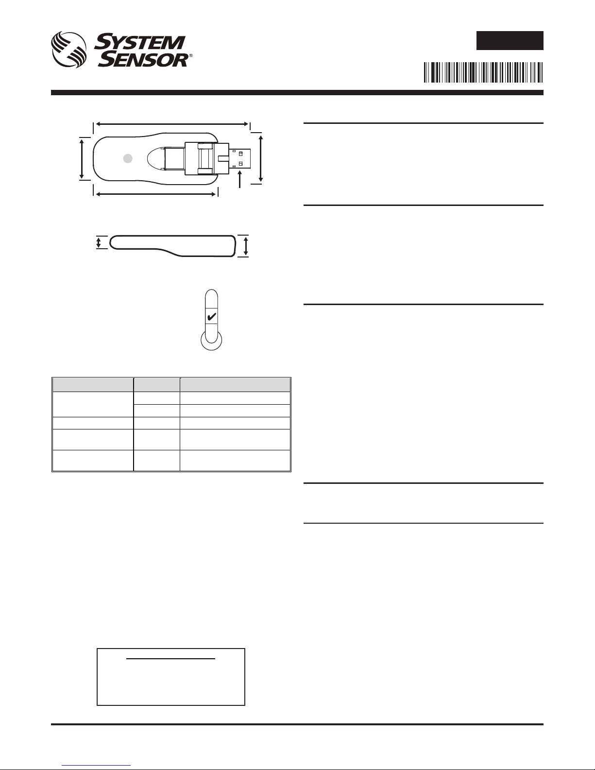
The M200WC-RF has an adjustable USB connector in order to
maximize the RF coupling with radio communicating devices, and
to change its prole when connected to a portable PC.
Do not connect the M200WC-RF interface until the correct
drivers have been installed on the target PC.
Download the latest version of the AgileIQ® radio interface software
(with the correct interface drivers) from a trusted source - see the
Radio Programming and Commissioning Manual for the installation
procedure.
Only plug the RF interface into a spare USB port on the PC
when requested.
Note that when the interface is attached, Windows may take a
number of seconds to recognize the new hardware correctly;
always wait a short period for the LED to change from yellow
to green before proceeding with any other operation.
LED INDICATORS
The interface is equipped with an RGB LED, giving an indication of
power and communication (both RF and USB) status (see table).
PROGRAMMING
Used in conjunction with the PC application software M200SCT-RF,
the RF interface is used to program and communicate with System
Sensor 200 Series RF re detection devices. For information on
setting-up, commissioning and monitoring an RF mesh network,
see the Radio Programming and Commissioning Manual - ref.
D200-306-00.)
NOTE: Do not run more than one interface at a time to
commission devices or carry out a site survey in an area.
M200WC-RF
RADIO SYSTEM USB INTERFACE
INSTALLATION AND USER INSTRUCTIONS
E N G L I S H
96 mm
31 mm
76 mm
26 mm
USB Connector
- Type A
(Hidden)
LED
13 mm
8.4 mm
0°C
50°C
M200WC-RF interface status LED
Status LED State Meaning
Power-on initialisation
Green pulse Device OK and connected
Amber ON Device OK but not recognized
Fault Amber blink Device has an internal trouble
Serial (USB)
communication
Green blink
Interface is receiving data from
the PC application
RF communication Blue blink
Interface is receiving data from
an RF device
Patents Pending
I 56- 41 57- 002
EU Declaration of Conformity
Hereby, Life Safety Distribution GmbH declares
that the radio equipment type M200WC-RF is in
compliance with directive 2014/53/EU
The full text of the EU DoC can be requested from:
HSFREDDoC@honeywell.com
Page 2
I56-4157-002 Pittway Tecnologica S.r.l. Via Caboto 19/3, 34147 TRIESTE, Italy
DESCRIZIONE
L’interfaccia M200WC-RF si collega a un PC/tablet attraverso
una porta USB e permette la comunicazione con i dispositivi
radio System Sensor. L’interfaccia M200WC-RF è alimentata
direttamente tramite la porta USB.
Tale dispositivo radio è rispetta i requisiti dello standard 2014/53/EU
in conformità alla Direttiva RED.
SPECIFICHE TECNICHE
Tensione di alimentazione: 4,3 – 5,5 V CC
Corrente di alimentazione: 33 mA tipica a 5 V CC
Standard USB: USB 2.0 (alta velocità)
Connettore USB: Tipo A
Frequenza radio: 865-870 MHz;
Potenza di uscita RF: 13 dBm (a 5 V)
Portata: 130 m (tip. in aria libera)
Umidità relativa: dal 10% al 93% (senza condensa)
INSTALLAZIONE
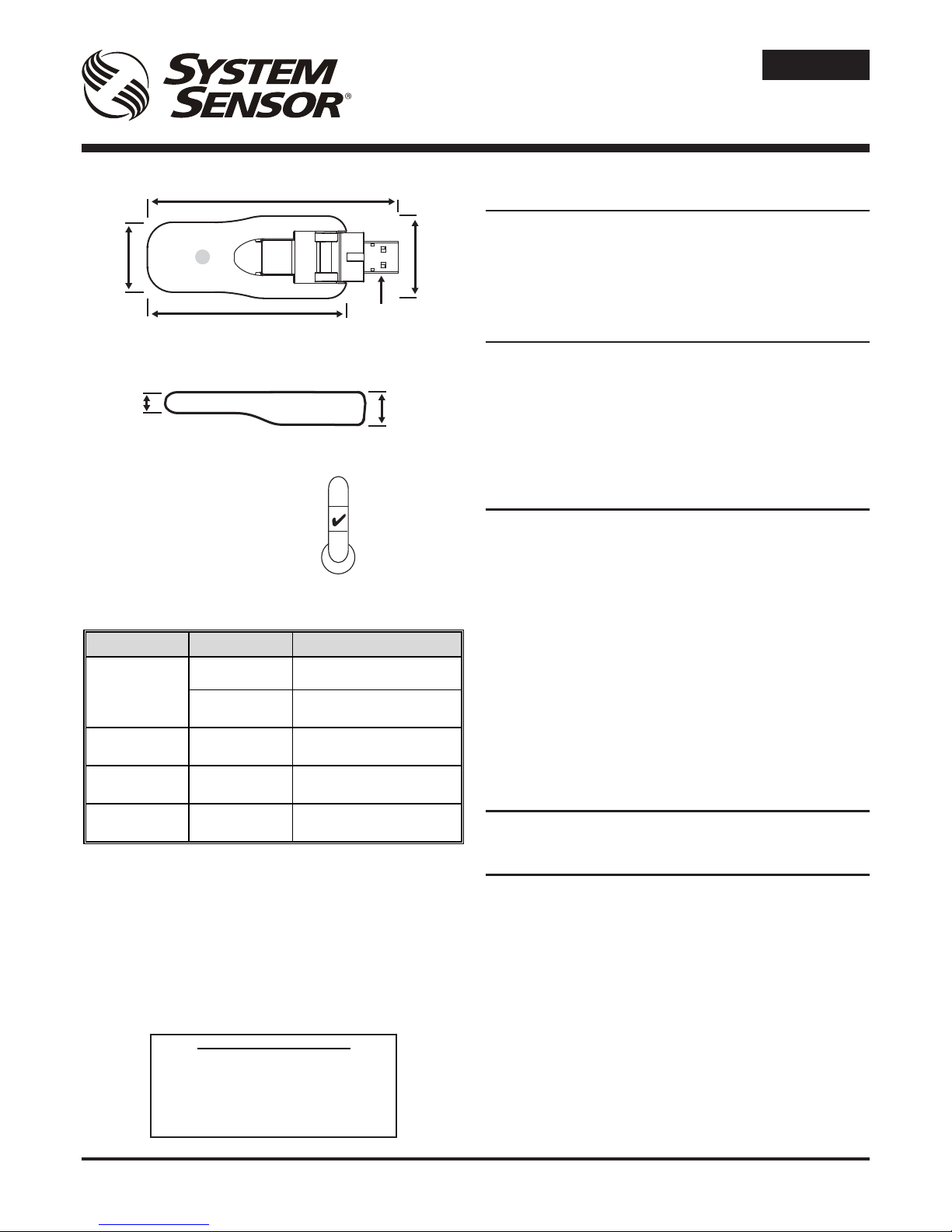
L’interfaccia M200WC-RF è dotata di un connettore USB snodabile
allo scopo di orientarla per massimizzare la portata radio, nonché
di ridurre l’ingombro quando collegata a un PC portatile o a un
tablet.
Collegare l’M200WC-RF solo dopo aver installato il software da
usare in combinazione con l’interfaccia sul PC di destinazione.
Scaricare la versione aggiornata del software AgileIQ® (assieme
ai drivers necessari) da una fonte afdabile – vedi il Manuale di
messa in esercizio e programmazione radio.
Connettere l’interfaccia radio a una porta USB libera solo
quando viene richiesto al software di installazione.
È bene ricordare che, al collegamento dell’interfaccia, è possibile
che al sistema operativo siano necessari alcuni secondi per
rilevare correttamente il nuovo hardware (passaggio del LED
del dispositivo da giallo a verde). Attendere brevemente prima
di procedere con qualsiasi altra operazione.
INDICATORI LED
L’interfaccia è dotata di un LED RGB, il quale segnala lo stato di
accensione e di comunicazione (sia radio, sia USB - vedi tabella).
PROGRAMMAZIONE
Utilizzata insieme al software applicativo per PC M200SCTRF, l’interfaccia RF consente di comunicare con i dispositivi
radio di rivelazione incendio System Sensor. Per informazioni
sulla congurazione, la messa in esercizio e il monitoraggio di
una rete radio, consultare il Manuale di messa in esercizio e
programmazione radio - rif. D200-306-00.
NOTA: Non eseguire in contemporanea più di una procedura
di congurazione o di analisi del sito alla volta.
ISTRUZIONI DI INSTALLAZIONE ED
USO PER INTERFACCIA RADIO-USB
M200WC-RF
ITALIANO
96 mm
31 mm
76 mm
26 mm
Connettore USB :
Tipo A
(nascosto)
LED
13 mm
8,4 mm
0°C
50°C
Brevetti in corso
LED di stato dell'interfaccia M200WC-RF
Stato Stato del LED Significato
Accensione
(nessun guasto)
Lampeggio verde Dispositivo OK e rilevato dal
sistema operativo
Acceso ambra
Dispositivo OK ma non è
stato ancora rilevato
Accensione
(guasto)
Luce ambra
intermittente
È stato rilevato un errore
interno del dispositivo
Comunicazione
seriale USB
Luce verde
intermittente
L'interfaccia sta ricevendo
dati via USB
Comunicazione
radio
Luce blu
intermittente
L'interfaccia sta ricevendo
dati via radio
Dichiarazione di Conformità UE
Il fabbricante, Life Safety Distribution GmbH
dichiara che il tipo di apparecchiatura radio
M200WC-RF è conforme alle Direttiva 2014/53/EU.
Il testo completo della Dichiarazione di Conformità
UE è disponibile presso:
HSFREDDoC@honeywell.com
Page 3

I56-4157-002 Pittway Tecnologica S.r.l. Via Caboto 19/3, 34147 TRIESTE, Italy
DESCRIPCIÓN
El modelo M200WC-RF es una interfaz que se conecta con un
PC a través de un puerto USB y permite la comunicación con los
dispositivos vía radio System Sensor 200 Series. M200WC-RF se
alimenta directamente a través del puerto USB.
Este dispositivo de radio cumple con los requisitos de 2014/53/EU,
según la directiva de equipos radioeléctricos (RED).
DATOS TÉCNICOS
Tensión de alimentación: 4,3 – 5,5V Corriente Continua (CC)
Corriente de alimentación: 33mA típica @ 5VCC
USB estándar: USB 2.0 (velocidad total)
Conector USB: Tipo A
Radiofrecuencia: 865-870 MHz;
Potencia de salida vía radio: 13 dBm (@ 5VCC)
Alcance: 130m (valor al aire libre)
Humedad relativa: del 10% al 93% (sin condensación)
INSTALACIÓN
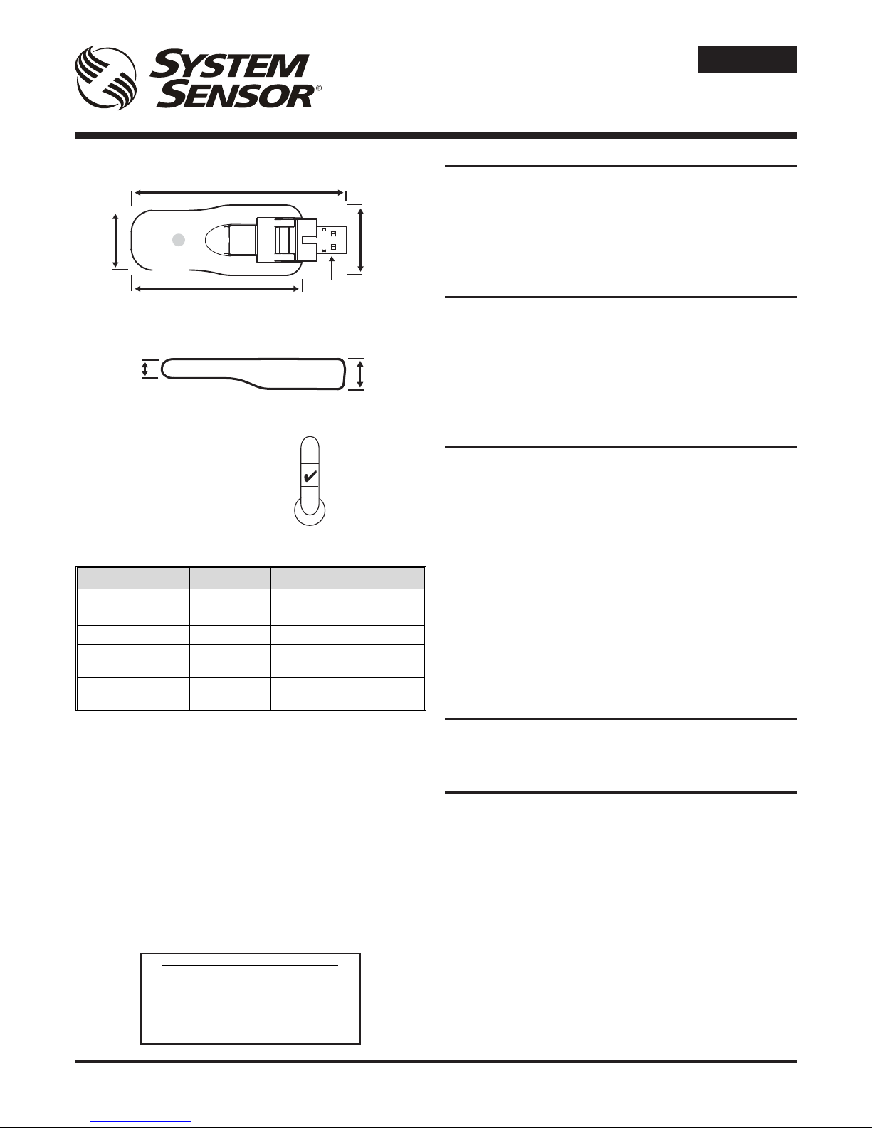
M200WC-RF tiene un conector USB ajustable con el n de
maximizar el acoplamiento con los dispositivos que se comunican
vía radio y para cambiar su perl cuando se conecta a un PC
portátil.
No conecte la interfaz M200WC-RF sin antes instalar los
drivers correctos en el PC con el que se vaya a conectar.
Descargue la versión más reciente del software de interfaz vía
radio AgileIQ® (con los controladores de interfaz correctos) desde
una fuente de conanza - véase el Manual de programación y
puesta en marcha vía radio.
Conecte la interfaz vía radio a un puerto USB del PC cuando
se solicite.
Tenga en cuenta que, cuando se conecte la interfaz, Windows
podría tardar unos segundos en reconocer correctamente el
nuevo hardware; espere a que el LED cambie de amarillo a
verde antes de continuar con cualquier otra operación.
INDICADORES DE LED
La interfaz cuenta con un LED RGB, que da indicaciones sobre el
estado de potencia y comunicación (vía radio y USB) (ver tabla).
PROGRAMACIÓN
Utilizada junto con el software de interfaz del equipo, la interfaz
vía radio se utiliza para programar y comunicarse con los
dispositivos de detección de incendios vía radio System Sensor
200 Series. Para más información sobre cómo congurar, poner
en funcionamiento y monitorizar una red en malla (mesh) vía radio,
consultar el Manual de programación y puesta en marchavía
radio - ref. D200-306-00.)
NOTA: No haga funcionar más de una interfaz al mismo
tiempo al poner en marcha dispositivos o llevar a cabo una
inspección del lugar en un área.
SISTEMA VÍA RADIO M200WC-RF
INTERFAZ USB
INSTRUCCIONES DE USO E INSTALACIÓN
ESPAÑOL
96 mm
31 mm
76 mm
26 mm
Conector USB :
Tipo A
(oculto)
LED
13 mm
8,4 mm
0°C
50°C
Patente pendiente
LED de estado del interfaz M200WC-RF
Estado Estado del
LED
Significado
Inicialización de
encendido
Pulsación
verde
Dispositivo OK y conectado
Ámbar
encendido
Dispositivo OK pero no
reconocido
Error
Ámbar
intermitente
El dispositivo tiene un problema
interno
Comunicación serial
(USB)
Verde
intermitente
La interfaz están recibiendo
datos de la aplicación para PC
Comunicación vía radio
Azul
intermitente
La interfaz están recibiendo
datos de un dispositivo vía
radio
Declaración EU de conformidad
Por la presente, Life Safety Distribution GmbH declara
que el tipo de equipo radioeléctrico M200WC-RF es
conforme con la Directiva 2014/53/EU.
El texto completo de la declaración UE de
conformidad está disponible. Puede solicitar el
documento a: HSFREDDoC@honeywell.com
Page 4
I56-4157-002 Pittway Tecnologica S.r.l. Via Caboto 19/3, 34147 TRIESTE, Italy
BESCHREIBUNG
Das M200WC-RF ist eine Schnittstelle, die an einem PC über
einen USB-Anschluss angeschlossen wird und die Kommunikation
mit kommerziellen HF-Geräten der Serie System Sensor 200
ermöglicht. Das M200WC-RF wird direkt über den USB-Anschluss
versorgt.
Dieses Funkgerät erfüllt die Anforderungen der 2014/53/EU
hinsichtlich der Konformität mit der RED Richtlinie.
TECHNISCHE DATEN
Betriebsspannung: 4.3 – 5.5V (DC)
Stromversorgung: 33mA typisch bei 5VDC
USB-Standard: USB 2.0 (volle Geschwindigkeit)
USB-Anschlussstecker: Typ A
Funkfrequenz: 865-870 MHz;
HF-Ausgangsleistung: 13 dBm (bei 5VDC)
Reichweite: 130m (typisch im Freien)
Relative Feuchtigkeit: 10% bis 93% (nicht kondensierend)
INSTALLATION
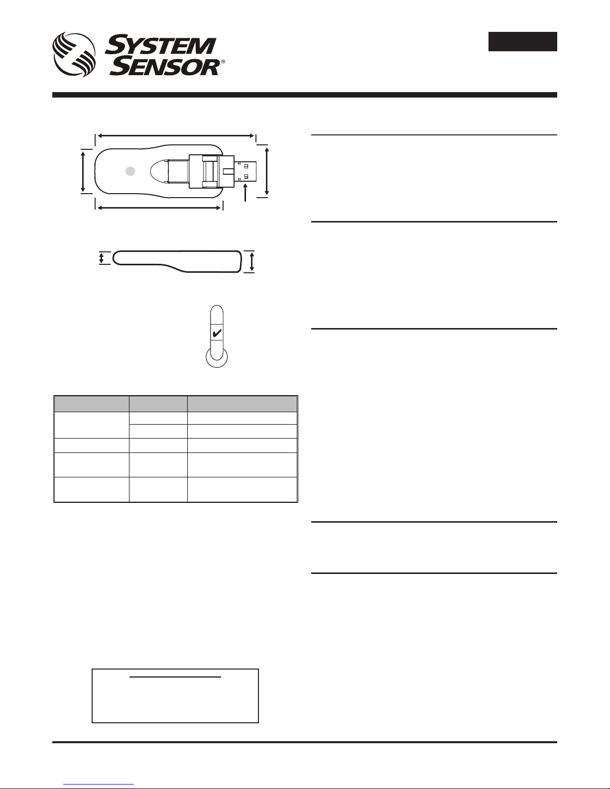
Das M200WC-RF hat einen einstellbaren USB-Anschlussstecker
um die HF-Verbindung mit Funkkomponenten zu optimieren. Es
kann für der Verwendung mit einem Notebook verstellt werden.
Verbinden Sie das M200WC-RF-Interface nicht mit dem PC
bevor die richtigen Gerätetreiber auf diesem PC installiert
worden sind.
Laden Sie neueste Version der AgileIQ®-Funkschnittstellensoftware
(mit dem richtigen Gerätetreiber) aus einer vertrauenswürdigen
Quelle – siehe Handbuch für Radio-Programmierung und
Inbetriebnahme für weitere Hinweise.
Stecken Sie das Interface nnur dann in einen freien USBAnschluss an Ihrem PC, wenn Sie dazu aufgefordert werden.
Manchmal kann es zu einigen Sekunden dauern, bis Windows
die neue Hardware korrekt erkennt; warten Sie immer bis die
LED von gelb auf grün wechselt bevor Sie mit den nächsten
Schritten weiter machen.
LED-ANZEIGEN
Die Schnittstelle ist mit einer RGB-LED ausgestattet, die den
Betrieb und den Kommunikationsstatus (sowohl für HF als auch
USB) anzeigt (siehe Tabelle).
PROGRAMMIERUNG
Bei Nutzung in Verbindung mit der PC-Anwendungssoftware PCAgileIQ® wird die HF-Schnittstelle für die Programmierung und
Kommunikation mit der HF-Brandmeldetechnik der Serie System
Sensor 200 verwendet. Für Informationen über die Einstellung,
Installation und Überwachung eines HF-Maschennetzes, siehe die
Funkprogrammier- und -installationsanleitung - Ref. D200-306-00.)
ANMERKUNG: Nicht mehr als eine Schnittstelle gleichzeitig
verwenden, um die Geräte im Umfeld zu installieren.
M200WC-RF FUNKSYSTEM
USB-SCHNITTSTELLE
INSTALLATIONS- UND GEBRAUCHSANLEITUNG
96 mm
31 mm
76 mm
26 mm
USB-Anschlussstecker
- Typ A
(versteckt)
LED
13 mm
8,4 mm
0°C
50°C
Angemeldete Patente
DEUTSCH
M200WC-RF Schnittstelle Status-LED
Status LED-Status Bedeutung
Einschaltinitialisierung
Grüner Impuls Gerät OK und verbunden
Gelb AN Gerät OK aber nicht erkannt
Fehler Gelb blinkend Gerät hat eine interne Störung
Serielle
Kommunikation (USB)
Grün blinkend
Die Schnittstelle empfängt
Daten von der PC-Anwendung
HF-Kommunikation Blau blinkend
Die Schnittstelle empfängt
Daten von einem HF-Gerät
Vereinfachte EU-Konformitätserklärung
Hiermit erklärt Life Safety Distribution GmbH, dass
der Funkanlagentyp M200WC-RF der Richtlinie
2014/53/EU entspricht.
Der vollständige Text der EU-Konformitätserklärung
ist unter der folgenden verfügbar:
HSFREDDoC@honeywell.com
Page 5
I56-4157-002 Pittway Tecnologica S.r.l. Via Caboto 19/3, 34147 TRIESTE, Italy
DESCRIPTION
Le M200WC-RF est un dongle qui peut être relié à un PC par un
port USB et qui permet la communication avec les dispositifs RF
commerciaux du modèle System Sensor 200. Le M200WC-RF est
alimenté directement à partir du port USB.
Le M200WC-RF répond aux exigences des norme 2014/53/EU en
ce qui concerne la conformité avec la directive RED.
CARACTÉRISTIQUES
Tension d’alimentation : 4,3 – 5,5 V CC
Courant d’alimentation : 33 mA valeur typique à 5 V CC
Standard USB : USB 2.0 (haute vitesse)
Connecteur USB : type A
Radiofréquence : 865-870 MHz
Puissance de sortie radiofréquence : 13 dBm (à 5 V CC)
Portée : 130 m (valeur typique à l’air libre)
Humidité relative : de 10 % à 93 % (sans condensation)
INSTALLATION
Le dongle USB M200WC-RF est équipé d’un connecteur USB
ajustable an d’optimiser son couplage RF avec les dispositifs
radio, et pour adapter son prol de fonctionnement lorsqu’il est
connecté à un ordinateur portable.
Ne pas connecter le dongle USB M200WC-RF avant l’installation
des pilotes sur l’ordinateur.
Télécharger la dernière version du logiciel AgileIQ™ ainsi que les
pilotes associés à partir d’une source sûre – se référer au manuel
de programmation et de mise en service pour plus de détails
concernant la procédure d’installation.
Sur demande du logiciel uniquement, brancher le dongle USB sur
un port USB libre de l’ordinateur.
Prendre en compte que lorsque le dongle USB est connecté,
Windows peut avoir besoin de quelques secondes pour reconnaître
correctement le nouveau matériel, attendre que la LED passes du
jaune au vert avant d’exécuter une autre opération.
INDICATEURS LED
Le dongle USB est équipé d’une LED qui indique les états de la
tension et de la communication (aussi bien radio que USB, cf. le
tableau).
PROGRAMMATION
En combinaison avec le logiciel de l’application M200SCT-RF
pour ordinateur, le dongle USB est utilisé pour programmer les
dispositifs radio de détection incendie de la gamme System
Sensor 200 et pour assurer la communication avec ces derniers.
(Pour plus d’informations sur la conguration, la mise en service et
le contrôle d’un réseau maillé, cf. le Manuel de programmation et
de mise en service radio - réf. D200-306-00.)
Important : Ne jamais mettre en service plus d’une interface
radio à la fois. Ne pas utiliser l’outil d’etude de site pendant la
phase de mise en service.
SYSTÈME RADIO M200WC-RF
DONGLE USB
MANUEL D’INSTALLATION ET D’UTILISATION
FRANÇAIS
96 mm
31 mm
76 mm
26 mm
Connecteur USB :
type A
(masqué)
LED
13 mm
8,4 mm
0°C
50°C
Brevets en attente
M200WC‐RFLEDindiquantl'étatdeledongle
État ÉtatLED Signification
Initialisationallumage
Impulsionverte DongleUSBOKetconnecté
JauneON DongleUSBOKmaisnonreconnu
Erreur Clignotantjaune Problèmeinternedudispositif
Communication
sérielle(USB)
Clignotantvert
Réceptiondedonnéesàpartirde
l'applicationsurordinateur
CommunicationRF Clignotantbleu
Réceptiondedonnéesàpartir
d'unDongleUSBencours
Déclaration UE de conformité
Le soussigné, Life Safety Distribution GmbH déclare
que l’équipement radioélectrique du type M200WC-RF
est conforme à la directive 2014/53/EU.
Le texte complet de la déclaration UE de conformité est
disponible à: HSFREDDoC@honeywell.com
 Loading...