

Page 1
D200-304-00 I56-3893-001 Pittway Tecnologica S.r.l. Via Caboto 19/3, 34147 TRIESTE, Italy
DESCRIPTION
The M200F-RF radio repeater is a battery operated RF device
designed for use with the M200G-RF radio gateway, running
on an addressable re system (using a compatible proprietary
communication protocol).
The repeater contains a wireless transceiver and plugs into the
B501RF wireless sensor base. It is used to extend the RF range of
the radio re detection system.
This device conforms to EN54-25 and EN54-18. It complies with
the requirements of EN 300 220 and EN 301 489 for conformance
with the R&TTE directive.
SPECIFICATIONS
Supply Voltage: 3.3 V Direct Current max.
Standby Current: 120 µA@ 3V (typical in normal operating mode)
Red LED Current Max: 4mA
Re-Sync Time: 35s (max time to normal RF communication from
device power on)
Batteries: 4 X Duracell Ultra123
Battery Life: 4 years @ 25oC
Radio Frequency: 865-870 MHz;
RF Output Power: 14dBm (max)
Range: 500m (typ. in free air)
Relative Humidity: 10% to 93% (non-condensing)
INSTALLATION
This equipment and any associated work must be installed in
accordance with all relevant codes and regulations.
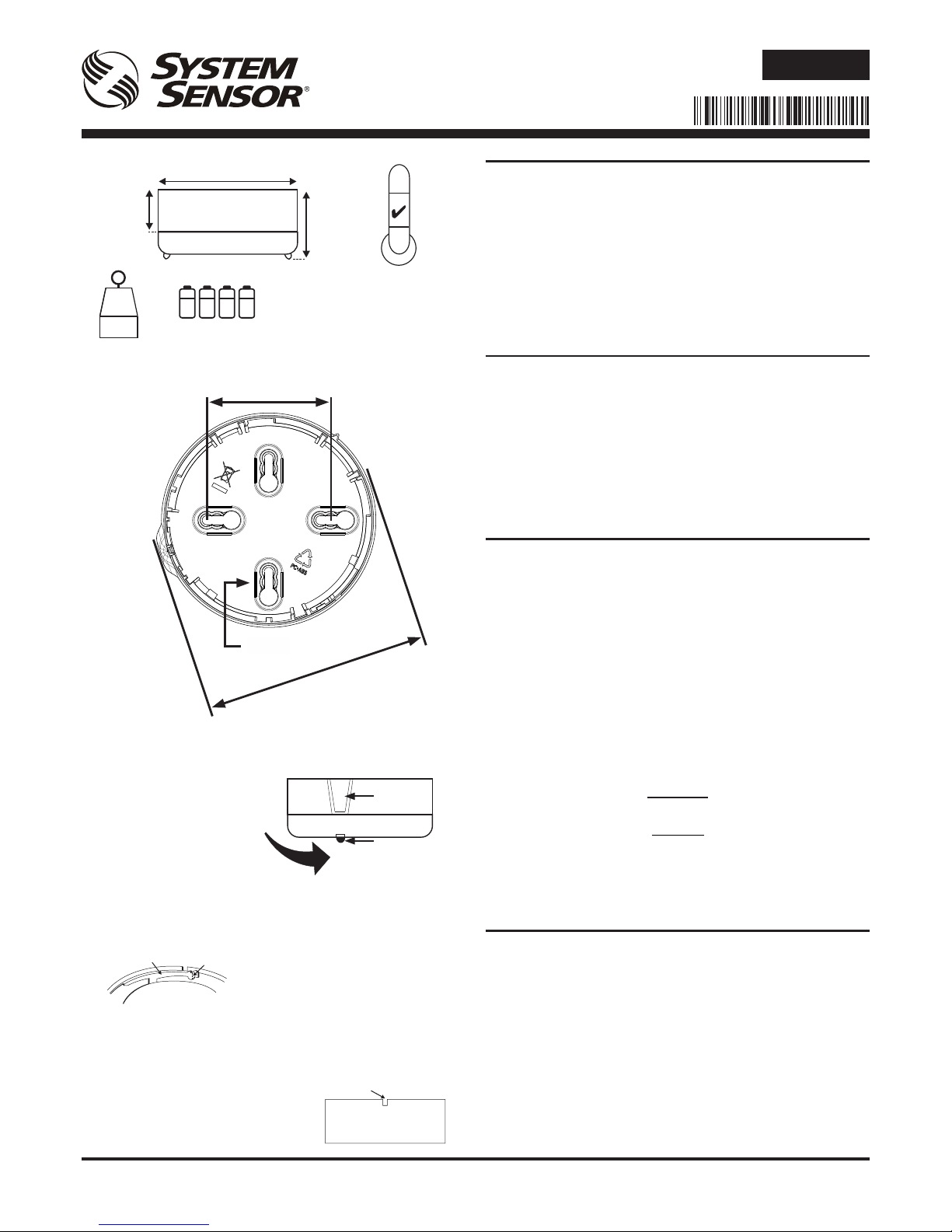
Figure 1 details the mounting of the B501RF base.
Spacing between radio system devices must be a minimum of 1m
Figure 2 details attaching the repeater to the base
Anti-Tamper Features
The base includes a feature that, when activated, prevents removal
of the repeater from the base without the use of a tool. See Figures
3a and 3b for details on this.
Head Removal Warning - An alert message is signalled to the CIE
via the Gateway when a repeater is removed from its base.
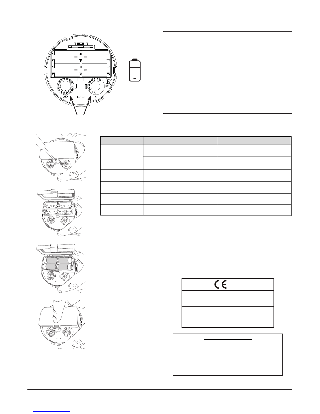
Figure 4 details the battery installation and the location of the
rotary address switches.
Important
Batteries should only be installed at the time of commissioning
Warning
Using these battery products for long periods at temperatures below
-20°C can reduce the battery life considerably (by up to 30% or more)
Observe the battery manufacturer’s precautions for use and
requirements for disposal
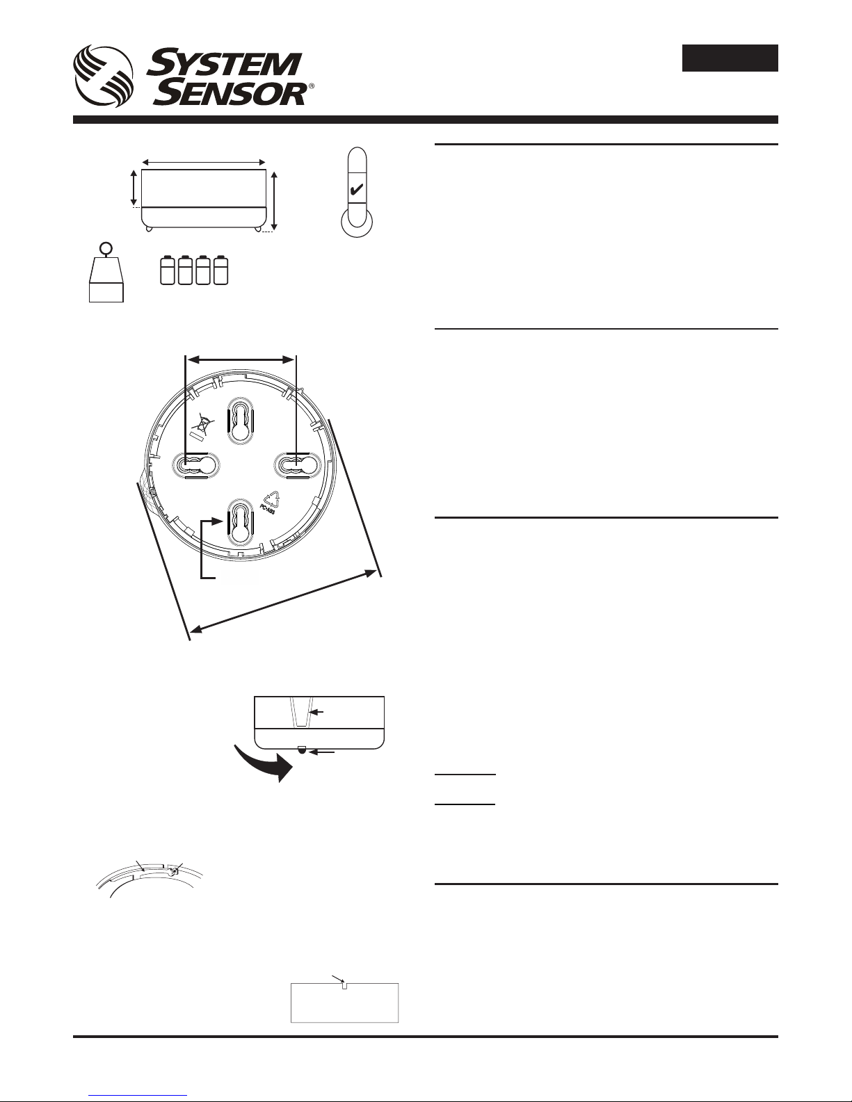
SETTING THE ADDRESS
Set the loop address by turning the two rotary decade switches on
the underside of the repeater (see gure 4), using a screwdriver
to rotate the wheels to the desired address. The repeater will take
one module address on the loop. Select a number between 01 and
159 (Note: The number of addresses available will be dependent
on panel capability, check the panel documentation for information
on this).
Insert the repeater into the base and rotate it clockwise until it locks
into place.
M200F-RF
RADIO SYSTEM REPEATER
INSTALLATION INSTRUCTIONS
E N G L I S H
PLASTIC LEVER
Figure 1: B501RF Mounting
Figure 3a: Activation of Tamper Resist Feature
Figure 2: Attaching the Repeater to the Base
-30°C
60°C
BREAK TAB AT DOTTED LINE BY
TWISTING TOWARDS CENTRE OF BASE
Figure 3b: Removing Repeater From Base if
Tamper Resist is Activated
USE A SMALL-BLADED SCREWDRIVER TO PUSH
PLASTIC IN THE DIRECTION OF THE ARROW
≤ M4
50-60 mm
104 mm
51 mm
32 mm
M200F-RF
B501RF
115 g
48 g
+=
229 g
(66 g)
107 mm
BULGE
IN BASE
REPEATER
LED
LINE UP REPEATER LED
WITH BULGE AND TWIST
CLOCKWISE (ONL Y ONE LED
WILL OPERATE AS KEY)
I 56- 3893- 001
Page 2
D200-304-00 I56-3893-001 Pittway Tecnologica S.r.l. Via Caboto 19/3, 34147 TRIESTE, Italy
PROGRAMMING
To load network parameters into the RF repeater, it is necessary
to link the RF gateway and the RF repeater in a conguration
operation. At commissioning time, with the RF network devices
powered on, the RF gateway will connect and programme them
with network information as necessary. The radio repeater then
synchronises with its other associated devices as the RF mesh
network is created by the gateway. (For further information, see the
Radio Programming and Commissioning Manual - ref. D200306-00.)
NOTE: Do not run more than one interface at a time to
commission devices in an area.
LED INDICATORS AND FAULT DESCRIPTION
The radio gateway has two LED indicators that show the status of
the device (see table below).
Figure 4: Battery Installation and Rotary Address Switches
NOTE POLARITY
4 x Duracell
Ultra 123
4c
4a
4d
4b
+
+
+
+
12
3
4
EN54-25: 2008 / AC: 2010 / AC: 2012
Components Using Radio Links
EN54-18: 2005 / AC: 2007 Input/Output Devices
for use in re detection and re alarm systems for buildings
0333 16
DOP-IRF006
Pittway Tecnologica S.r.l.
Via Caboto 19/3, 34147 Trieste, Italy
+
ROTAR Y ADDRESS SWITCHES
Repeater Status LEDs
Repeater Status LED State Meaning
Power-on initialisation
(no fault)
Long Green pulse Device is un-commissioned
(factory default)
3 Green blinks Device is commissioned
Fault Blink Amber every 1s. Device has an internal trouble
Un-commissioned
Red/Green double-blink every 14s
(or just Green when communicating).
Device is powered and is waiting to be
programmed.
Sync
Green/Amber double-blink every 14s
(or just Green when communicating).
Device is powered, programmed and
trying to find/join the RF network.
Normal
Controlled by panel; can be set to Red
ON, periodic blink Green or OFF.
RF communications is established;
device is working properly.
Idle (low power mode) Amber/Green double-blink every 14s
Commissioned RF network is in standby;
used when the gateway is powered off.
EC Declaration of Conformity
In accordance with EN60950 and 1999/5/EC R&TTE Directive
This product complies with the following Directive(s):
2006/95/EC Low Voltage
2004/108/EC Electromagnetic Compatibility
The full DoC can be obtained from System Sensor Europe
Patents Pending
Page 3
D200-304-00 I56-3893-001 Pittway Tecnologica S.r.l. Via Caboto 19/3, 34147 TRIESTE, Italy
DESCRIZIONE
Il ripetitore radio M200F-RF è un dispositivo a radiofrequenza
alimentato a batteria, progettato per essere impiegato con il
gateway M200G-RF . Contiene un ricetrasmettitore e viene integrato
in un sistema antincendio indirizzabile tramite un protocollo di
comunicazione proprietario.
Il ripetitore si inserisce nella stessa base dei sensori wireless,
la B501RF. È usato per ampliare la zona di copertura radio del
sistema di rivelazione antincendio.
Il presente dispositivo è a norma EN54-25 ed EN54-18, e rispetta
i requisiti di cui agli standard EN 300 220 ed EN 301 489 per la
conformità alla Direttiva R&TTE.
SPECIFICHE TECNICHE
Tensione di alimentazione: 3,3 V CC max
Corrente di standby: 120 µA a 3 V CC (tipica in modo di
funzionamento normale)
Corrente LED rosso: 4 mA max
Tempo di risincronizzazione: 35 s (tempo max dall’accensione del
dispositivo alla normale comunicazione RF
quando la rete è attiva)
Batterie: 4 Duracell Ultra 123
Durata delle batterie: 4 anni a 25oC
Frequenza radio: 865-870 MHz;
Potenza di uscita RF: 14 dBm (max)
Range: 500 m (tipico in aria libera)
Umidità relativa: dal 10% al 93% (senza condensa)
INSTALLAZIONE
L’installazione del presente dispositivo e di eventuali impianti
associati deve essere eseguita in conformità a tutti i codici e i
regolamenti pertinenti.
Nella gura 1 è illustrato in dettaglio il montaggio della base B501RF.
La distanza tra i dispositivi di un sistema radio deve essere di
almeno 1 metro
Nella gura 2 è illustrato in dettaglio il montaggio del ripetitore sulla
base.
Funzioni antimanomissione
La base è dotata di un dispositivo antimanomissione che, una volta
attivato, impedisce la rimozione del ripetitore senza l’impiego di un
utensile. Vedere le gure 3a e 3b per altre informazioni.
Avviso di rimozione del sensore - Un messaggio di avviso viene
trasmesso al pannello di controllo tramite il gateway quando il
ripetitore viene rimosso dalla base.
Nella gura 4 sono illustrati l’alloggiamento batterie e i selettori rotanti.
Importante - Installare le batterie esclusivamente al momento
della messa in esercizio
Attenzione - L’uso di prodotti a batteria a temperature inferiori
a -20°C per periodi prolungati può ridurre considerevolmente
la durata delle batterie (no al 30% o più)
Rispettare le avvertenze del produttore delle batterie in merito
al loro impiego e smaltimento
IMPOSTAZIONE DELL’INDIRIZZO
Per impostare l’indirizzo, usare i due selettori rotanti situati sul lato
inferiore del ripetitore (vedere gura 4) ruotandoli servendosi di un
cacciavite in modo da comporre l’indirizzo desiderato. Il ripetitore
occupa l’indirizzo di un modulo cablato sulla linea. Selezionare un
numero tra 01 e 159 (Nota: il numero di indirizzi a disposizione
dipende dal pannello di controllo. Consultare la documentazione
del pannello per ulteriori informazioni).
ISTRUZIONI DI INSTALLAZIONE ED USO
PER RIPETITORE RADIO
M200F-RF
LINGUETTA DI
PLASTICA
Figura 1: Montaggio B501RF
Figura 3a: Attivazione della funzione antimanomissione
Figura 2: Montaggio del ripetitore sulla base
-30°C
60°C
ROMPERE LA LINGUETTA IN
CORRISPONDENZA DELLA LINEA
TRATTEGGIATA TORCENDOLA IN
DIREZIONE DEL CENTRO DELLA BASE
Figura 3b: Rimozione del ripetitore dalla base
con la funzione antimanomissione attivata
USARE UN CACCIAVITE A TAGLIO PER SPINGERE
LA LINGUETT A ANTIMANOMISSIONE IN DIREZIONE DELLA FRECCIA
≤ M4
50-60 mm
104 mm
51 mm
32 mm
M200F-RF
B501RF
115 g
48 g
+=
229 g
(66 g)
107 mm
ALLOGGIAMENTO
DEL MAGNETE
RIPETITORE
LED
ALLINEARE IL LED
DEL RIPETITORE CON
L’ALLOGGIAMENTO DEL
MAGNETE SULLA BASE,
QUINDI RUOTARE IN SENSO
ORARIO (SOLTANTO UN LED
FUNZIONA COME CHIAVE)
ITALIANO
Page 4

D200-304-00 I56-3893-001 Pittway Tecnologica S.r.l. Via Caboto 19/3, 34147 TRIESTE, Italy
PROGRAMMAZIONE
Per congurare il ripetitore radio, è necessario seguire una
procedura di programmazione (congurazione) che coinvolge
anche il gateway: una volta programmato con i dati della rete, il
gateway è in grado di congurare tutti i dispositivi radio ad esso
associati, già installati nella loro posizione denitiva (per ulteriori
informazioni, consultare il Manuale di messa in esercizio e
programmazione radio - rif. D200-306-00).
NOTA: Non eseguire in contemporanea più di una procedura
di congurazione alla volta.
STATO DEI LED E INDICAZIONI
Il ripetitore radio è dotato di due LED che indicano lo stato del
dispositivo.
Figura 4: Alloggiamento delle batterie e
selettori rotanti per l‘indirizzamento
FARE ATTENZIONE
ALLE POLARITÀ
4 Duracell
Ultra 123
4c
4a
4d
4b
+
+
+
+
12
3
4
EN54-25: 2008 / AC: 2010 / AC: 2012
Componenti che utilizzano collegamenti radio
EN54-18: 2005 / AC: 2007 Dispositivi di ingresso/uscita
per l’utilizzo in sistemi di rivelazione e segnalazione
d’incendio installati in edici
0333 16
DOP-IRF006
Pittway T ecnologica S.r.l.
Via Caboto 19/3, 34147 Trieste, Italy
+
SELETTORI ROTANTI
Brevetti in corso
Dichiarazione di Conformità CE
Ai sensi della norma EN60950 e della Direttiva R&TTE 1999/5/CE
Il presente prodotto è conforme alle seguenti Direttive:
2006/95/CE Bassa tensione
2004/108/CE Compatibilità elettromagnetica
Il testo completo della Dichiarazione di Conformità è disponibile
presso System Sensor Europe
Stato del ripetitore e LED
Stato del ripetitore Stato del LED Significato
Accensione
(nessun guasto)
Lampeggio verde lungo Dispositivo non configurato
(impostazioni di fabbrica)
Tre lampeggi verdi Dispositivo configurato
Accensione (guasto)
Luce ambra intermittente a
intervalli di 1 secondo
È stato rilevato un errore
interno del dispositivo
Non configurato
Lampeggio rosso/verde a
intervalli di 14 secondi
(impulso verde in caso di un
messaggio ricevuto)
Il dispositivo è acceso ed è in
attesa di essere configurato
Configurato
Lampeggio verde/ambra a
intervalli di 14 secondi
(impulso verde in caso di un
messaggio ricevuto )
Il dispositivo è acceso,
configurato e sta tentando di
connettersi alla rete radio
Normale (configurato
e connesso alla rete
radio)
I LED sono comandati dal
pannello di controllo
La rete radio ed il dispositivo
funzionano correttamente
Disattivazione
temporanea
(modalità di
risparmio energetico)
Lampeggio ambra/verde a
intervalli di 14 secondi
La rete radio è
momentaneamente
disattivata; modalità utilizzata
quando il gateway è spento
Page 5

D200-304-00 I56-3893-001 Pittway Tecnologica S.r.l. Via Caboto 19/3, 34147 TRIESTE, Italy
DESCRIPCIÓN
El repetidor M200F-RF es un dispositivo vía radio el uso con la
pasarela vía radio M200G-RF , utilizado en un sistema antiincendios
direccionable (utilizando un protocolo de comunicación compatible).
El repetidor contiene un transceptor vía radio y se conecta a la
base vía radio B501RF. Se utiliza para extender el alcance vía
radio del sistema de detección de incendios vía radio.
Este dispositivo cumple las normas EN54-25 y EN54-18. además
de los requisitos de EN 300 220 y EN 301 489 según la directiva
R&TTE.
DATOS TÉCNICOS
Tensión de alimentación: 3,3 V corriente continua máx.
Corriente en reposo: 120 µA@ 3V (típica en el modo de
funcionamiento normal)
Corriente máx LED rojo: 4mA
Tiempo de resincronización: 35s (tiempo máximo para establecer la
comunicación vía radio normal desde el
encendido del dispositivo)
Pilas: 4 X Duracell Ultra123
Duración de las pilas: 4 años a 25oC
Radiofrecuencia: 865-870 MHz;
Potencia de salida vía radio: 14dBm (máx)
Alcance: 500m (valor en aire libre)
Humedad relativa: del 10% al 93% (sin condensación)
INSTALACIÓN
Este equipo, así como cualquier actividad asociada, se debe
instalar cumpliendo todas las normas y leyes relevantes.
La gura 1 ilustra el montaje de la base de B501RF.
El espacio entre varios dispositivos con sistema vía radio debe ser
como mínimo de 1m
La gura 2 muestra la conexión del repetidor a la base.
Características anti-manipulación
La base incluye una función que, cuando se activa, previene que se
pueda quitar el repetidor de la base sin el uso de una herramienta.
Consultar las Figuras 3a y 3b para más detalles.
Aviso de extracción de la cabeza - Cuando un repetidor se quita
de su base, la central (CIE) recibe un mensaje de alerta mediante
la pasarela.
La gura 4 muestra la instalación de la batería y la ubicación de
los selectores giratorios de dirección. Congurar la dirección lazo
antes de instalar las baterías (ver sección siguiente).
Importante
Instalar las pilas sólo en el momento de la puesta en funcionamiento
Aviso
Usar estos productos a pilas durante largos períodos a temperaturas
inferiores a -20°C puede reducir considerablemente la duración de
las pilas (hasta el 30% o más)
Se deben cumplir las medidas de precaución indicadas por el
fabricante para el uso y eliminación de los dispositivos
CONFIGURACIÓN DE LA DIRECCIÓN
Antes de instalar las baterías, Congurar la dirección del lazo
girando los dos interruptores giratorios de 10 posiciones situados
en la parte inferior del repetidor (ver gura 4), utilizando un
destornillador para girar las ruedas en la dirección deseada. El
repetidor tomará una dirección del módulo en el lazo. Seleccionar
un número entre 01 y 159 (Nota: el número de direcciones
disponibles dependerá de la capacidad del panel; comprobar la
documentación del panel para más información).
M200F-RF
REPETIDOR DE SISTEMA VÍA RADIO
INSTRUCCIONES DE INSTALACIÓN
PALANCA DE
PLÁSTICO
Figura 1: Montaje de B501RF
Figura 3a: Activación de la función anti-manipulación
Figura 2: Conexión del repetidor a la base
-30°C
60°C
ROMPER LA LENGÜETA EN LA LÍNEA DE
PUNTOS GIRÁNDOLA HACIA EL CENTRO
DE LA BASE
Figura 3b: Extracción del repetidor de la base
si la función anti-manipulación está activada
CON LA AYUDA DE UN DESTORNILLADOR PEQUEÑO DE
PUNTA PLANA, EMPUJAR EL PLÁSTICO EN DIRECCIÓN DE
LA FLECHA
≤ M4
50-60 mm
104 mm
51 mm
32 mm
M200F-RF
B501RF
115 g
48 g
+=
229 g
(66 g)
107 mm
SALIENTE
EN LA BASE
REPETIDOR
LED
ALINEAR EL LED DEL
REPETIDOR CON EL
SALIENTE Y GIRAR EN EL
SENTIDO DE LAS AGUJAS
DEL RELOJ (SÓLO UN LED
FUNCIONARÁ COMO LLAVE)
ESPAÑOL
Page 6

D200-304-00 I56-3893-001 Pittway Tecnologica S.r.l. Via Caboto 19/3, 34147 TRIESTE, Italy
Introducir el repetidor en la base y girarlo en el sentido de las
agujas del reloj hasta que encaje en su sitio.
PROGRAMACIÓN
Para cargar los parámetros de red en el repetidor vía radio, es
necesario asociar la pasarela vía radio y el repetidor vía radio. En
el momento de la puesta en funcionamiento, con los dispositivos
de red vía radio activados, la pasarela vía radio programará
los dispositivos con información de red según sea necesario. A
continuación, el repetidor vía radio se sincronizará con los demás
dispositivos asociados mientras la pasarela crea la red en malla
(mesh) vía radio (para más información, consultar el Manual de
programación y puesta en funcionamiento vía radio - ref.
D200-306-00.)
NOTA: Congurar las interfaces una a una para poner en
funcionamiento los dispositivos en un área.
INDICADORES LED Y DESCRIPCIÓN DE AVERÍAS
La pasarela vía radio cuenta con dos indicadores LED que
muestran el estado del dispositivo (ver la tabla siguiente).
Figura 4: Instalación de las pilas y selectores
giratorios de dirección
TENER EN CUENTA
LOS POLOS
4 x Duracell
Ultra 123
4c
4a
4d
4b
+
+
+
+
12
3
4
EN54-25: 2008 / AC: 2010 / AC: 2012
Componentes que utilizan conexiones vía radio
EN54-18: 2005 / AC: 2007 IDispositivos de entrada/salida
para el uso en sistemas de detección y alarma de
incendios para edicios
0333 16
DOP-IRF006
Pittway T ecnologica S.r.l.
Via Caboto 19/3, 34147 Trieste, Italy
+
SELECTORES GIRATORIOS DE DIRECCIÓN
Patente pendiente
Declaración de conformidad CE
Cumplimiento de las directivas EN60950 y 1999/5/CE R&TTE
Este producto cumple la(s) siguiente(s) directiva(s):
2006/95/CE Límite de tensión
2004/108/CE Compatibilidad electromagnética
Documento completo disponible de System Sensor Europe
LEDs de estado del repetidor
Estado del repetidor Estado del LED Significado
Inicialización de
encendido
(ningún fallo)
Pulsación verde larga El dispositivo no está en funcionamiento
(valores por defecto)
3 luces verdes intermitentes El dispositivo está en funcionamiento
Error Luz intermitente ámbar cada 1s El dispositivo tiene un problema interno
No está en
funcionamiento
Luz roja/verde doble intermitente cada
14 s
(o sólo verde en comunicación).
El dispositivo está encendido y en espera
de programación.
Sincronización
Luz verde/ámbar doble intermitente cada
14 s
(o sólo verde en comunicación).
El dispositivo está encendido y
programado y está intentando
encontrar/conectarse con la red vía radio.
Normal
Controlado por el panel, se puede
configurar en rojo encendido,
intermitencia periódica verde o apagado.
Las comunicaciones vía radio se han
establecido; el dispositivo funciona
correctamente.
Inactivo (modo de
bajo consumo)
Luz ámbar/verde doble intermitente cada
14 s
La red vía radio en funcionamiento está
en standby; se utiliza cuando la pasarela
está apagada.
Page 7

D200-304-00 I56-3893-001 Pittway Tecnologica S.r.l. Via Caboto 19/3, 34147 TRIESTE, Italy
BESCHREIBUNG
Der M200F-RF Repeater ist ein batteriebetriebenes HFGerät für die Nutzung mit dem Funkgateway M200G-RF einer
adressierbaren Brandmeldeanlage (mit Einsatz eines kompatiblen
Kommunikationsprotokolls).
Der Repeater beinhaltet einen drahtlosen Empfänger und wird
in dem Funk-Meldersockel B501RF montiert. Er wird für die
Erweiterung der HF-Reichweite der Funk-Brandmeldeanlage
genutzt.
Dieses Gerät entspricht den Normen EN54-25 und EN54-18.
Es erfüllt die Anforderungen der EN 300 220 und EN 301 489
hinsichtlich der Konformität mit der R&TTE-Richtlinie.
TECHNISCHE DATEN
Betriebsspannung: 3,3 V DC.
Ruhestrom: 120 µA bei 3V (typisch in normalem
Betriebsmodus)
Max. Strom rote LED: 4mA
Resynchronisierungsdauer: 35s (Höchstdauer bis zu normaler HF-
Kommunikation nach Einschalten vom Gerät)
Batterien: 4 X Duracell Ultra123
Lebensdauer der Batterien: 4 Jahre bei 25°C
Funkfrequenz: 865-870 MHz;
HF-Ausgangsleistung: 14dBm (max.)
Reichweite: 500m (typisch im Freien)
Relative Feuchtigkeit: 10% bis 93% (nicht kondensierend)
INSTALLATION
Dieses Gerät und alle verbundenen Anlagen müssen im Einklang mit
allen sachbezogenen Normen und Vorschriften installiert werden.
Abbildung 1 zeigt die Montage des Sockels B501RF.
Der Abstand zwischen Funksystemkomponenten muss
mindestens 1m betragen
Abbildung 2 zeigt die Anbringung des Repeaters an die Basis
Entnahmesicherung
Der Sockel verfügt über eine Einrichtung, die das Entfernen des
Repeaters ohne den Gebrauch eines Werkzeugs verhindert, wenn
sie aktiviert ist. Siehe Abbildungen 3a und 3b für Details.
Warnung bei Entfernen des Repeaters - Bei Entfernen
des Repeaters aus dem Sockel geht über das Gateway eine
Störungsmeldung an die Brandmeldeanlage.
Abbildung 4 zeigt die Batterieinstallation und die Lage der
Adressdrehschalter.
Wichtig: Stellen Sie immer erst die Geräteadresse ein, bevor
Sie die Batterien einsetzen. Die Batterien erst zum Zeitpunkt
der Inbetriebnahme einsetzen.
Warnung
Bei längerem Einsatz bei Temperaturen von unter -20°C kann
sich die Lebensdauer der Batterien beträchtlich verringern
(bis zu 30% und mehr).
Die Vorsichtsmaßnahmen des Herstellers hinsichtlich des
Gebrauchs und die Anforderungen an der Entsorgung sind
zu beachten
EINSTELLEN DER ADRESSE
Die Ringbusadresse durch Drehen der beiden Drehschalter auf
der Unterseite des Repeaters einstellen (siehe Abbildung 4).
Dazu einen Schraubendreher verwenden, um die Rädchen bis
zur gewünschten Adresse zu drehen. Der Repeater entspricht
einer Ringbusadresse auf der Ringbusleitung. Wählen Sie eine
Adresse zwischen 01 und 159 (Anmerkung: Die Anzahl der
verfügbaren Adressen hängt von der Ausbaustufe der Zentrale ab.
Für weitere diesbezügliche Informationen ist die Dokumentation
der Brandmeldeanlage zu Rate zu ziehen.)
M200F-RF
FUNKSYSTEM-REPEATER INSTALLATIONSANLEITUNG
KUNSTSTOFFHEBEL
Abbildung 1: B501RF Montage
Abbildung 3a: Aktivierung der Entnahmesicherung
Abbildung 2: Einsetzen des Repeaters in den Meldersockel
-30°C
60°C
Abbildung 3b: Entfernen des Repeaters vom
Sockel, wenn die Entnahmesicherung aktiviert ist
EINEN SCHMALEN SCHRAUBENDREHER VERWENDEN,
UM DAS KUNSTSTOFFTEIL IN PFEILRICHTUNG ZU DRÜCKEN
≤ M4
50-60 mm
104 mm
51 mm
32 mm
M200F-RF
B501RF
115 g
48 g
+=
229 g
(66 g)
107 mm
WÖLBUNG
IN DEM SOCKEL
REPEATER
LED
DEN REPEATER AN DER
WÖLBUNG AUSRICHTEN
UND IM UHRZEIGERSINN
DREHEN (NUR EINE LED
FUNKTIONIERT ALS
SCHLÜSSEL)
DEUTSCH
AN DER PUNKTIERTEN LINIE DURCH
BIEGEN ZUM MITTELPUNKT DES
SOCKELS HIN ABKNICKEN
Page 8

D200-304-00 I56-3893-001 Pittway Tecnologica S.r.l. Via Caboto 19/3, 34147 TRIESTE, Italy
Den Repeater in den Meldersockel einstecken und im Uhrzeigersinn
drehen, bis er einrastet.
PROGRAMMIERUNG
Um die Netzwerkparameter auf den HF-Repeater zu laden, sind
das HF-Gateway und der HF-Repeater mit einander zu verbinden.
Zum Zeitpunkt der Installation verbindet sich das HF-Gateway
mit den eingeschalteten HF-Netzwerkgeräten und programmiert
diese mit den Netzwerkinformationen, soweit dies notwendig ist.
Der Repeater synchronisiert sich mit den anderen verbundenen
Geräten, wenn das HF-Netzwerk durch das Gateway hergestellt
wurde. (Für weitere Informationen bitte die Funkprogrammierung-
und -inbetriebnahmeanleitung beachten - D200-306-00)
ANMERKUNG: Nicht mehr als eine Schnittstelle gleichzeitig
verwenden, um die Geräte in Ihrer Umgebung zu installieren.
LED-ANZEIGEN UND FEHLERBESCHREIBUNG
Das Funk-Gateway hat zwei LED-Anzeigen, die den Gerätestatus
anzeigen (siehe Tabelle unten).
Abbildung 4: Batterieinstallation und Adressdrehschalter
POLARITÄT
BEACHTEN
4 x Duracell
Ultra 123
4c
4a
4d
4b
+
+
+
+
12
3
4
EN54-25: 2008 / AC: 2010 / AC: 2012
Bestandteile, die Hochfrequenz-Verbindungen nutzen
EN54-18: 2005 / AC: 2007 Eingangs-/Ausgangsgeräte
für den Einsatz in Brandmelde- und Feueralarmanlagen
für Gebäude
0333 16
DOP-IRF006
Pittway T ecnologica S.r.l.
Via Caboto 19/3, 34147 Trieste, Italy
+
ADRESSDREHSCHALTER
Angemeldete Patente
EG-Konformitätserklärung
Gemäß EN60950 und 1999/5/EG R&TTE-Richtlinie
Dieses Produkt entspricht den folgenden Richtlinien:
2006/95/EG Niederspannungsrichtlinie
2004/108/EG Elektromagnetische Verträglichkeit
Die vollständige Liste ist verfügbar System Sensor Europe
Status-LEDs Repeater
Repeater-Status LED-Status Bedeutung
Einschaltinitialisierung
(keine Störung)
Langer, grüner Impuls
Gerät ist nicht installiert
(Werkseinstellung)
3-mal grünes Blinken Gerät ist installiert
Fehler Gelbes Blinken alle 1 Sekunde Gerät hat eine interne Störung
Nicht installiert
Rot/grünes Doppelblinken alle 14 Sekunden
(oder nur grün, wenn die Kommunikation
läuft).
Das Gerät ist eingeschaltet und bereit
für die Programmierung.
Synchronisierung
Grün/gelbes Doppelblinken alle 14
Sekunden
(oder nur grün, wenn die Kommunikation
läuft).
Das Gerät ist eingeschaltet,
programmiert und versucht, das HFNetzwerk zu finden/sich damit zu
verbinden.
Normal
Panelgesteuert; kann auf rot ON, grünes
Blinken oder OFF gestellt werden.
Die HF-Kommunikation ist eingerichtet,
das Gerät arbeitet einwandfrei.
Nicht in Betrieb
(Schwachstrommodus)
Gelb/grünes Doppelblinken alle 14
Sekunden
Das installierte HF-Netzwerk ist im
Stand by-Modus. Dies geschieht, wenn
das Gateway ausgeschaltet ist.
Page 9

D200-304-00 I56-3893-001 Pittway Tecnologica S.r.l. Via Caboto 19/3, 34147 TRIESTE, Italy
DESCRIPTION
Le répétiteur radio M200F-RF est un dispositif RF fonctionnant sur
piles, conçu pour une utilisation avec l’interface radio M200G-RF
via un système adressable de détection incendie (utilisant un
protocole de communication propriétaire compatible).
Le répétiteur comporte un transmetteur radio, et se connecte sur le
socle détecteur sans l B501 RF et permet d’étendre la portée RF
du système radio de détection incendie.
Ce transmetteur radio conforme aux normes NF EN 54-25 et NF
EN 54-18. Il répond aussi aux exigences des normes EN 300 220
et EN 301 489 pour conformer avec la directive R&TTE.
SPECIFICATIONS
Tension d’alimentation : 3,3 V Courant Continu (DC) max
Courant de veille : 120 µA à 3V (nominal)
Courant max de l’LED Rouge : 4mA
Temps de resynchronisation : 35s max à partir de la mise en route
Piles : 4 x Duracell Ultra 123
Durée de vie des piles : 4 ans à 25°C
Bande Fréquence Radio : 865-870 MHz
Puissance de sortie RF : 14dBm (max)
Portée : 500m (std / à l’air libre)
Humidité Relative : 10% à 93% (sans condensation)
INSTALLATION
Cet équipement et le câblage associé doivent être installés
conformément aux règlementations en vigueur.
Se reporter à la Figure 1 concernant l’installation du socle B501 RF.
La distance entre des dispositifs radio doit être un minimum de 1m.
Se reporter à la Figure 2 concernant montage du répétiteur dans
son socle.
Système Antivol
Le socle comprend un système qui, lorsqu’il est mis en œuvre,
empêche le retrait du répétiteur de son socle. Pour plus de détails
se reporter aux Figures 3a et 3b.
Alerte Retrait Tête
Un message d’alerte est signalé à la centrale via l’interface
lorsqu’un répétiteur est retiré de son socle.
Se reporter à la Figure 4 pour plus de détails sur l’installation des
piles et roues codeuses (sélection adresse).
Important
Installer les piles uniquement au moment de la mise en service
Avertissement
L’usage de ces produits fournit des piles dans les températures
au dessus de -20°C pour les périodes prolongés peut réduire
considérablement la vie des piles (peut être plus que 30%)
Respecter les préconisations du fabricant de batteries en
matière d’utilisation et de mise au rebut
PARAMETRAGE DE L’ADRESSE
Sélectionner l’adresse de boucle désirée en tournant les deux
roues codeuses en dessous du répétiteur à l’aide d’un tournevis
(voir gure 4). Le répétiteur occupe une adresse de module sur
la boucle de détection. Sélectionner un nombre entre 01 et 159
(Note: Le nombre d’adresses disponibles dépendra de la capacité
du tableau de détection incendie, consultez sa documentation
pour avoir des informations à ce sujet).
Insérer le répétiteur sur son socle et tourner le dans le sens des
aiguilles d’une montre jusqu’au verrouillage.
MANUEL D’INSTALLATION
REPETITEUR SYSTEME RADIO M200F-RF
LEVIER PLASTIQUE
Figure 1: Montage du socle B501RF
Figure 3a: Mise en oeuvre du dispositif Antivol
Figure 2: Montage du répétiteur dans son socle
-30°C
60°C
BRISER L’ENCOCHE EN EXERCANT UNE
TORSION VERS LE CENTRE DU SOCLE
Figure 3b: Retrait de l’interface de son socle
UTILISER UN TOURNEVIS PLAT AFIN DE POUSSER
LE PLASTIQUE DANS LA DIRECTION DE LA FLECHE
≤ M4
50-60 mm
104 mm
51 mm
32 mm
M200F-RF
B501RF
115 g
48 g
+=
229 g
(66 g)
107 mm
BOMBEMENT
DU SOCLE
LEDS DU
RÉPÉTITEUR
ALIGNER UN DES LEDS
DU RÉPÉTITEUR AVEC LE
BOMBEMENT DU SOCLE
ET LE TOURNER À DROITE.
NOTER QUE LA CLÉ
ENTRE LE RÉPÉTITEUR ET
LE SOCLE NE PERMET LE
MONTAGE QUE DANS UN
SENSE
FRANÇAIS
Page 10

D200-304-00 I56-3893-001 Pittway Tecnologica S.r.l. Via Caboto 19/3, 34147 TRIESTE, Italy
PROGRAMMATION
Pour charger les paramètres réseau du répétiteur RF, il est
nécessaire de lier l’interface et le répétiteur RF via une opération
de conguration. A la mise en service, avec les dispositifs RF
du réseau dès la mise en marche, l’interface radio pré-installée
se connecte et les programme avec des informations réseau si
nécessaire. Ensuite le répétiteur radio se synchronise avec les
autres dispositifs associés tandis que la topologie du réseau RF
est créée par l’interface. (Pour plus d’informations, se reporter au
Manuel de Programmation et de Mise en Service Radio - réf.
D200- 306-00.)
Note: N’utilise pas plus qu’un dongle au même temps dans
un endroit pendant le mise en marche des dispositifs.
INDICATEURS LED ET DESCRIPTION DERANGEMENT
L’interface Radio dispose de deux LED indiquant l’état du répétiteur.
Figure 4: Installation des piles et
Roues Codeuses (Sélection Adresse)
ATTENTION
A LA POLARITE +/-
4 x Duracell
Ultra 123
4c
4a
4d
4b
+
+
+
+
12
3
4
EN54-25: 2008 / AC: 2010 / AC: 2012
Composants utilisant des liaisons radioélectriques
EN54-18: 2005 / AC: 2007 Dispositif entrée/sortie
Systèmes de détection et d’alarme incendie
0333 16
DOP-IRF006
Pittway Tecnologica S.r.l.
Via Caboto 19/3, 34147 Trieste, Italy
+
ROUES CODEUSES (SÉLECTION ADRESSE)
LEDs Etat Répétiteur
Etat du Répétiteur Etat LED Signification
Mise en route (pas de
dérangement)
Clignotant lent vert Dispositif non programmé (défaut
de l’usine)
3 clignotes en vert Dispositif est mis en service
Dérangement Clignote en jaune toutes les 1s Dérangement interne du dispositif
Dispositif non-programmé Double clignotement rouge/vert
toutes les 14s (ou juste en vert en
état de communication).
Dispositif alimenté et en attente
de programmation.
Synchronisation Double clignotement vert/jaune
toutes les 14s (ou juste en vert en
état de communication).
Répétiteur alimenté, programmé
et en phase de synchronisation
avec le réseau radio.
Normal Commandé par la centrale : Rouge
fixé, (en alarme feu), clignotement
périodique en vert ou éteint.
Communication RF établie.
Dispositif en fonctionnement
normal.
Veille
(mode basse consommation)
Double clignotement jaune/vert
toutes les 14s.
Réseau RF en état de veille.
Utilisé quand l’interface n’est pas
disponible (pas sous tension)
Brevets en cours
Déclaration de conformité CE
En accord avec les Directives
EN60950 et RTTE 1999/5/CE
Ce produit est conforme aux directives suivantes :
2006/95/CE basse tension
2004/108/CE Compatibilité Electromagnétique
L’ensemble de la documentation peut être obtenu à
partir de System Sensor Europe
 Loading...