

System Sensor i4 Series COSMO-2W, i4 Series COSMO-4W Installation And Maintenance Instructions Manual
Page 1
INSTALLATION AND MAINTENANCE INSTRUCTIONS
i4 Series Combination Carbon
I56-3747-001R
Monoxide(CO)/Photoelectric Smoke Detector
COSMO-2W (2-wire) and COSMO-4W (4-wire)
SPECIFICATIONS COSMO-2W COSMO-4W
Electrical Specifications Physical Spcecificaitons
System Voltage: 12/24 volts DC 12/24 volts DC Operating Temperature Range: 0 - 50° C (32 - 122° F)
Min: 8.5 volts 8.5 volts Operating Humidity Range: 20-95% RH
Max: 35 volts 35 volts Storage Temperature Range: -10 - 70° C (14 - 158° F)
Max Startup Current: 200uA 200uA Diameter: 5.5 inches
Max Standby Current: 50uA 50uA Height: 2.5 inches
Max Alarm Current: 50mA 40mA Weight: 9.2 oz; 261 g
Max Reverse Polarity Current: 20mA 20mA Wire Gauge Acceptance: Min: 22 AWG Max: 14 AWG
Audible Signal (Supplemental*): 85dBA 85dBA 2-Wire Compatibility Zone Identifier: A
Max Start-up Capacitance: .10uF .10uF
*NFPA requires a UL listed sounder on the NAC circuit
Notice: This manual shall be left with the owner/user of this equipment.
BEFORE INSTALLATION
Please read this manual thoroughly along with manual I56-3871 for the i4
series interface module and the Application Guides for System Sensor Smoke
(A05-1003) and CO Detectors (A05-1099), which provide detailed information
on detector spacing, placement, zoning, wiring, and special applications. Copies of these manuals are available at systemsensor.com.
IMPORTANT: This detector must be tested and maintained regularly following
NFPA 72/NFPA 720 requirements. At a minimum, cleaning and
testing should be performed annually.
GENERAL DESCRIPTION
The i4 series is a plug-in, system-connected, combination carbon monoxide/
smoke detector. It is available in either a 2-wire or 4-wire configuration. The i4
series detectors must be used with the corresponding i4 series Interface Module to connect to the panel. The i4 interface module is also compatible with i3
series smoke detector model 2WTA-B or 4WTA-B.
FEATURES
Smoke Features
• Photoelectric smoke sensor
• Drift compensation and noise rejection algorithms
• Red smoke LED indicator
• Smoke test switch
CO Features
• Field replaceable, electrochemical CO sensor
• RealTest® functional test capable
• Blue CO LED indicator
• Sensor end-of-life notification
Audible Annunciation
• Local integral sounder
• Polarity reversal
Installation and Maintenance
• Stop-Drop-N-Lock plug-in base
• SEMS wiring terminals
• COSMO-2W designed for 2-wire i4 Zone type
• COSMO-4W designed for 4-wire i4 Zone type
• SENS-RDR sensitivity reader compatible with extended range
• Removable cover for cleaning
• Replaceable screen
Other Features
• Green supervisory LED
• Listed to UL standards 268 and 2075
VISIBLE ANNUNCIATON
The i4 series detector has three visible LED’s; Green, Red and Blue. The green
LED is a supervisory LED; it blinks during power on, reset, and during normal
operation. It is extinguished during smoke maintenance, CO trouble, smoke
SS-500-003 1 I56-3747-001R
alarm and CO alarm events. The red LED signals smoke events; it blinks during smoke maintenance events and lights constantly during smoke alarm
events. The blue LED signals CO events; it blinks blue during CO trouble or
CO end-of-life; it blinks rapidly during RealTest®; and lights constant during
CO alarm.
TABLE 1: OPERATION MODES
OPERATION
MODE
Normal (standby) Blink 5 Sec. OFF OFF OFF
Alarm Smoke OFF ON OFF Temp 3
Alarm CO OFF OFF ON Temp 4
Alarm Smoke & CO OFF ON ON Temp 3
RealTest® Mode OFF OFF Blink 1 Sec. OFF
(After CO is Sprayed) OFF OFF ON Temp 4
Trouble feature: When the sensor (supervision) is in a trouble condition
(such as a detector that is dirty), the detector will send a trouble signal to the
module then to the FACP. Depending on the issue, the detector must then be
serviced or replaced.
CO sensor end-of-life timer feature: When the CO sensor has passed end-oflife, a trouble signal will be sent to the module then to the FACP. This indicates
that the CO sensor inside the detector must be replaced. If unresolved for 30
days, the detector will chirp intermittently. The typical life of the CO sensor
is six years from the date of manufacture; it is recommended to periodically
check the “Replace by” sticker located on the replaceable CO cell.
INSTALLATION GUIDELINES
Ceiling: Detector should be at least 12 inches from any wall.
Wall: Detector should be no closer than 6 inches from ceiling.
• Do not install outdoors or in any environment that does not comply with
the detector’s environmental specifications
• Install in accordance with NFPA 72 and 720 standards. NFPA 72 and
720 define standards for both commercial and residential installation of
smoke and CO detectors. State and local laws involving CO detection
should also be considered.
• If the installation can be interpreted as residential, consult the section
of NFPA 720 that outlines residential applications. Chapter 9.4.1.1, for
example, states that carbon monoxide alarms or detectors shall be installed as follows:
• Outside each separate dwelling unit sleeping area in the immediate
vicinity of the bedroom
• On every level of a dwelling unit, including basements
• Consult NFPA 72, the local Authority Having Jurisdiction (AHJ), and/
or applicable codes for specific information regarding the spacing and
placement of smoke detectors.
• Do not install detectors in the following areas:
• In or near areas where particles of combustion are normally present such as
3825 Ohio Avenue, St. Charles, Illinois 60174
1-800-SENSOR2, FAX: 630-377-6583
www.systemsensor.com
GREEN
LED
RED LED BLUE LED SOUNDER
Page 2
kitchens, in garages, near furnaces, hot water heaters, or gas space heaters.
WARNING
• In very cold or very hot areas.
• In wet or excessively humid areas, or next to bathrooms with showers.
• In dusty, dirty, or insect-infested areas.
• Near fresh air inlets or returns or excessively drafty areas. Air conditioners, heaters, fans, and fresh air intakes and returns can drive
smoke away from the detector.
Note: This unit is UL listed as containing a supplemental sounder and should
not be used as a primary sounder for evacuation.
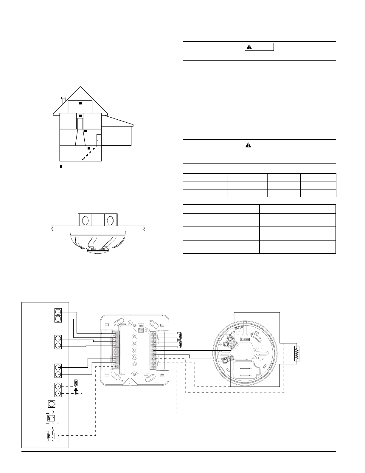
FIGURE 1: ALARM LOCATION DIAGRAM FOR RESIDENTIAL APPLICATION
BEDROOM
TO
BR
BEDROOM BEDROOM
LIVING
ROOM
KITCHEN
CLOSED
DOOR
GARAGE
S0295-01
BASEMENT
–
CARBON MONOXIDE/SMOKE ALARM
LOCATION FOR MULTI-LEVEL RESIDENCE
MOUNTING
The i4 detector can be ceiling mounted or wall mounted:
1. To a single gang box, 2 in. by 4 in. box, 3½ in. or 4 in. octagonal or 3½
in. or 4 in. round ceiling
2. Direct mount to ceiling or to wall using drywall fasteners
FIGURE 2: MOUNTING OF DETECTOR
S0326-00
WIRING INSTALLATION GUIDELINES
All wiring must be installed in compliance with the NFPA 70 standards, National Electrical Code, applicable state and local codes.
The screw terminals in the mounting base will accept 14-22 gauge wire. Wire
connections are made by stripping approximately 3/8" to ½" of insulation from
FIGURE 3: COSMO-2W WIRING DIAGRAM
ALL CIRCUITS ARE SUPERVISED
(EXCEPT TRIGGERS) AND MUST
SMOKE
BE POWER LIMITED
AUXPOWER
(resettable)
the end of the feed wire, inserting it into the proper base terminal, and tightening the screw to secure the wire in place. Do not put wires more than 2
gauge apart under the same clamping plate.
Remove power from alarm control unit or initiating device circuits before installing detectors.
1. Remove detector from packaging and separate the base from the detector head.
2. Wire the detector base screw terminals.
3. Screw the base of the detector onto an electrical box, or to the surface of
the wall or ceiling using the hardware included in the packaging.
4. Attach the detector head to the base by applying light pressure and rotating clockwise. The detector will lock in place when properly aligned.
5. After all detectors have been installed, apply power to the alarm control
unit. Refer to Table 3 for time to LED stabilization. Once stabilized, the
green LED will blink once every 5 seconds.
6. Test each detector as described in the Testing section.
7. Notify the proper authority that the system is in operation.
CAUTION
NFPA 72 recommends the installation of detectors only after completing construction or
any other dust producing activity
TABLE 2: LED INDICATION DURING POWER UP SEQUENCE
Green LED Red LED Blue LED
No Power OFF OFF OFF
Power on Reset Blink 5 Sec. Blink 5 Sec. Blink 5 Sec.
TABLE 3: POWER UP TIME TO FIRST ALARM / LED STABILIZATION
Power Up Time 45 Seconds
Power up time after
10 second reset
LED Indication time
Status LED indication
stabilization time
15 Seconds
Typical: 45 seconds
Maximum: 55 seconds
Typical: 55 seconds
Maximum: 268 seconds
TESTING
The detector must be tested after installation. The detector has two discrete
test switches, one for smoke testing and one for CO testing. The detector may
also be functionally tested using canned smoke and canned CO.
NOTE: Before testing, notify the proper authorities to avoid any nuisance alarms.
Ensure the proper wiring and power is applied to the detector. After power
up, allow approximately 5 minutes for the detector to stabilize before testing.
SMOKE
ZONE
CO
ZONE
MAINT.
ZONE
BELL
OR
SMOKE
TRIGGER OUT
CO
TRIGGER
OUT
Panel
EOL
Resistor
SS-500-003 2 I56-3747-001R
COSMOD2W
Panel
EOL
Resistors
LOOP STYLE D WIRING
COSMO-2W
3.9k
RESISTOR
(supplied
with module)
S0329-00
Page 3
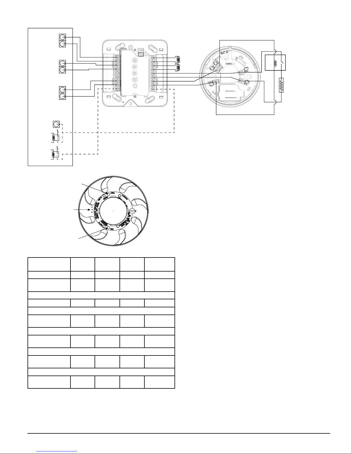
FIGURE 4: COSMO-4W WIRING DIAGRAM
SMOKE
POWER
(resettable)
ALL CIRCUITS ARE SUPERVISED
(EXCEPT TRIGGERS) AND MUST
BE POWER LIMITED
SMOKE
ZONE
CO
ZONE
COSMOD4W
Panel
EOL
Resistors
COSMO-4W
EOL
RELAY
#EOLR-1
3.9k
RESISTOR
(supplied
with module)
BELL
OR
SMOKE
TRIGGER OUT
CO
TRIGGER
OUT
FIGURE 5: TEST BUTTON LOCATION AND OPERATION
3. If the detector is within the listed sensitivity limits, the sounder will
alarm temporal 3 and the red alarm LED will light up.
TEST BUTTON
SMOKE
SMOKE SENSITIVITY READING
To measure the detector’s smoke sensitivity, the Infrared Sensitivity Reader
model #SENS-RDR should be used.
1. Point the SENS-RDR directly to the center of the detector at a distance of 1 to
GAS ENTRY
PORTS
10 feet. A broomstick can be attached to the SENS-RDR for extended reach.
2. The sensitivity will be displayed on the SENS-RDR. The SENS-RDR will
also display “replace” if a detector is found faulty.
SMOKE ENTRY TEST
TEST BUTTON
CARBON MONOXIDE
S0327-00
TABLE 4: LED INDICATION & SOUNDER DURING TEST AND MAINTENANCE
GREEN
LED
Smoke Maintenance OFF Blink 5 Sec. OFF OFF
CO Trouble/
End-of-Life
Simultaneous Smoke Maintenance & CO Trouble/EOL
EZ Walk Test® – Normal
EZ Walk® – Smoke Maintenance
EZ Walk® – CO Trouble/End-of-Life
EZ Walk® – Smoke Maintenance & CO Trouble/End-of-Life
OFF OFF Blink 5 Sec.
OFF Blink 5 Sec. Blink 5 Sec. OFF
Double
Blink 5 Sec.
OFF
OFF OFF
OFF
RED LED
OFF OFF OFF
Double
Blink 5 Sec.
Double
Blink 5 sec.
BLUE
LED
OFF OFF
Double
Blink 5 sec.
Double
Blink 5 sec.
SOUNDER
Intermittent chirp
after 30 days
OFF
OFF
*NOTE: EZ Walk applies to COSMO-2W 2-wire model only.
SMOKE TEST SWITCH
1. A recessed smoke test switch is located on the detector housing and
identified by text that says "TEST" next to it and “SMOKE” above it. It is
the switch closest to the red LED. (See Figure 5)
1. With the detector in standby mode, spray UL listed compatible, canned
smoke into the detector.
2. When the detector senses the presence of the smoke, the sounder will
alarm temporal 3 and the red alarm LED will illuminate.
Note: On some panels, resetting a smoke alarm may require additional steps
at the keypad to clear the trouble conditions on CO and smoke maintenance zones due to power loss to the module.
LOOP VERIFICATION (MODEL #COSMO-2W ONLY)
Loop verification is provided by the EZ Walk loop test feature. This feature is
for use with compatible control panels and System Sensor 2-wire detectors (i4
Series model COSMO-2W and i3 Series model 2WTA-B) installed with the COSMOD2W interface module only. The EZ Walk loop test verifies the initiating
loop wiring and provides visual status indication at each detector:
1. Ensure proper wiring and power is applied. Wait approximately 6 minutes after power-up before performing the EZ Walk test.
2. Place COSMOD2W interface module into EZ Walk test mode by depressing the recessed test button on the COSMOD2W Interface Module.
3. Observe the LED’s at each detector.
NOTE: The EZ Walk loop test should not be used in lieu of functional testing
(alarm, trouble and other functional tests) of the system.
CO TEST SWITCH
1. A recessed CO test switch is located on the detector housing and identified by text that says “TEST” next to it and “CARBON MONOXIDE”
above it. (See Figure 5)
2. With the detector in standby mode, use a small screwdriver to press and release the CO test switch. Pressing the switch one time will enter into RealTest®
Mode (see instructions below), pressing two times will enter test mode.
3. If the test is successful, the blue LED will light up. The detector and module will automatically reset within 60 seconds.
If the detector fails either of the above test methods the CO cell or the detector
should be replaced.
2. With the detector in standby mode, use a small screwdriver to press and
release the smoke test switch.
SS-500-003 3 I56-3747-001R
S0330-00
Page 4
FUNCTIONAL GAS TEST
REPLACEABLE CO CELL
Solo C6 brand canned CO may be used to verify the detector’s ability to sense
CO by utilizing the RealTest® feature as follows:
1. Press and release the test switch once as described in Testing above. The blue
LED will start blinking rapidly indicating it is RealTest® mode. If the detector
will not go into RealTest® mode, the CO sensor may be in fault or at end-of-life.
2. While the blue LED is blinking, spray a small amount of canned CO directly into the CO gas entry ports from ¼” away. (See Figure 5)
3. The detector will go into alarm if the gas entry was successful and the
cell is functioning properly.
4. The CO test will automatically clear when the CO clears or in 30 seconds
if no CO was introduced.
NOTE: Testing the detector will activate the alarm and send a signal to the panel.
Carbon monoxide gas may be present in other areas.
This detector is NOT:
• A substitute for the proper servicing of fuel-burning appliances or the
sweeping of chimneys.
• To be used on an intermittent basis, or as a portable alarm for the spillage of combustion products from fuel-burning appliances or chimneys.
Carbon monoxide gas is a highly poisonous gas which is released when fuels
are burnt. It is invisible, has no smell and is therefore impossible to detect with
the human senses. Under normal conditions in a room where fuel burning appliances are well maintained and correctly ventilated, the amount of carbon
monoxide released into the room by appliances should not be dangerous.
SYMPTOMS OF CARBON MONOXIDE POISONING
Carbon monoxide bonds to the hemoglobin in the blood and reduces the amount
of oxygen being circulated in the body. The following symptoms are examples
taken from NFPA 720; they represent approximate values for healthy adults.
Concentration (ppm CO) Symptoms
200 Mild Headache after 2-3 hours of exposure
400 Headache and nausea after 1-2 hours of exposure
800 Headache, nausea, and dizziness after 45 minutes of expo-
sure; collapse and unconsciousness after 2 hours of exposure
Many cases of reported carbon monoxide poisoning indicate that while victims are aware that they do not feel well, they become so disoriented that they
are unable to save themselves by either exiting the building or calling for assistance. Also young children and pets may be the first to be affected.
CO ALARM ACTIVATION
Per UL standard 2075, the i4 series detector has been tested to the sensitivity
limits defined in UL standard 2034.
TABLE 6: CO ALARM THRESHOLDS
Parts per Million (ppm) Detector Response Time (Min.)
30+-3ppm No alarm within 30 days
70+-5ppm 60-240
150+-5ppm 10-50
400+-10ppm 4-15
What to do if the carbon monoxide detector goes into alarm:
Immediately move to a spot where fresh air is available, preferably outdoors.
Find a phone in an area where the air is safe and call your security service
provider. Tell your provider the detector alarm status, and that you require
professional assistance in ridding your home of the carbon monoxide.
MAINTENANCE
NOTE: Before performing any maintenance on the detector, notify the proper
authorities that maintenance is being performed and the system will
be temporarily out of service. Disable the zone or system undergoing
maintenance to prevent any unwanted alarms. Power must be removed
from the detector before performing maintenance of any kind.
CLEANING
1. Remove the detector head by turning counterclockwise.
2. Clean the outside casing with a cloth. Ensure that the holes on the front
of the alarm are not blocked with dirt and dust. Canned air can be used
to remove any dust or debris.
SS-500-003 4 I56-3747-001R
©2012 System Sensor
3. Remove the white cover of the screen/sensing chamber located in the
center of the detector head by turning counterclockwise.
4. Remove the black screen/sensing chamber by pulling up on it.
5. Use canned air to remove any dust or particles that are present on both
the chamber cover/screen and chamber itself.
6. Replace the top half of the screen/sending chamber by aligning the two
arrows on the chamber cover with the notches in the detector head. Press
down until the screen/sensing chamber is fully seated.
7. Replace the white cover by placing it over the screen/sensing chamber
and turning it clockwise until it snaps into place
8. Reattach the detector head to the base by applying light pressure and
rotating clockwise. The detector will lock in place when properly aligned.
9. Test the detector to insure it is fully functional. (See Testing section)
10. Notify the proper authorities when the system is back in service.
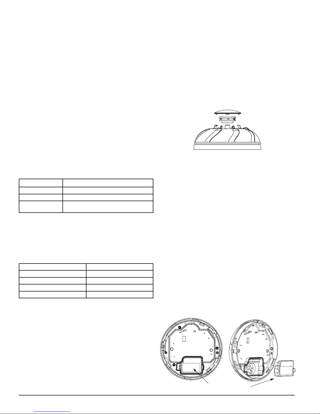
FIGURE 6: REMOVING/REPLACING SCREEN/SENSING CHAMBER
Do not paint, and do not use cleaning agents, bleach or polish the detector.
LIMITED LIFE OF CO SENSOR
This detector is manufactured with a long-life carbon monoxide sensor. Over
time the sensor will lose sensitivity, and will need to be replaced. A replacement CO sensor, model #CO-REPL, is available. The life span of the CO sensor
is approximately six years from the date of manufacture.
Periodically check the detector’s replacement date. Remove the detector head
and refer to the sticker placed on the replaceable CO cell.. The sticker will
indicate the date the CO cell should be replaced.
Reminder: This detector is also equipped with a feature that will signal the
panel once the CO sensor has passed the end of its’ useful life. If
this occurs, it is time to replace the CO sensor.
REPLACEMENT OF CO SENSOR
1. Remove the detector head by turning counterclockwise.
2. Locate the CO sensor on the back side of the detector head.
(Refer to Figure 7)
3. Depress the 2 tabs on the CO sensor and pull it out.
4. Insert replacement CO sensor model CO-REPL.
5. Reattach the detector head to the base by applying light pressure and
rotating clockwise. The detector will lock in place when properly aligned.
6. Test the detector to insure it is fully functional. (See Testing section)
7. Notify the proper authorities when the system is back in service.
NOTE: Before replacing the sensor or detector, notify the proper authorities
that maintenance is being performed and the system will be temporarily out of service. Disable the zone or system undergoing maintenance
to prevent any unwanted alarms. Follow the proper testing protocol as
outlined in the Testing section to make sure the device is functioning
properly. Dispose of detector in accordance with any local regulations.
FIGURE 7: CO SENSOR REPLACEMENT
S0333-00
 Loading...