

Page 1
INSTALLATION AND MAINTENANCE INSTRUCTIONS
DH100 Series Duct Smoke Detector
Replacement Detector Board
Replacement Detector Boards
Ionization Detector Board: part number A5052
Photoelectric 2-Wire Detector Board: part number A5180
Photoelectric 4-Wire Detector Board: part number A5190
NOTE: PHOTOELECTRIC DETECTOR BOARDS CAN ONLY
BE INSTALLED IN PHOTOELECTRIC DUCT SMOKE
DETECTOR MODELS; IONIZATION DETECTOR BOARDS
CAN ONLY BE INSTALLED IN IONIZATION DUCT SMOKE
DETECTOR MODELS.
IMPROPER INSTALLATION WILL VOID ALL AGENCY APPROVALS.
Detector Board Replacement Instructions
1. Notify the proper authorities that the smoke detector system is undergoing
maintenance and that the detector will temporarily be out of service.
2. Turn off power to the duct smoke detector.
3. Remove the two detector board mounting screws.
Retain screws for installation of new board.
4. Pull gently on the board to remove it from the detector housing.
3825 Ohio Avenue, St. Charles, Illinois 60174
1-800-SENSOR2, FAX: 630-377-6495
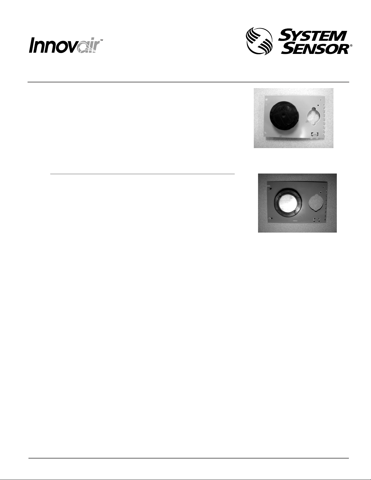
A5180/A5190: Photoelectric
Detector Board
A5052: Ionization
Detector Board
A Division of Pittway
5. Align the board mounting features, holes, and interconnect terminals
with the features on the duct smoke detector housing.
6. Push the board into place.
7. Secure the board with the two board mounting screws.
8. Perform the detector checks as outlined in sections 6.2.1 and 6.2.2.1 of the Installation and Maintenance
Instructions to ensure proper detector operation. The tests performed must include:
A. Visually check to see the green power LED blinks once every ten seconds, indicating power to the duct
smoke detector. If the green LED does not flash, the detector lacks power (check wiring, panel or power
supply), the detector board is missing (install), or the unit is defective (return for replacement).
B. Perform the magnet test to initiate an alarm condition. Reset the detector using the local reset button,
remote accessory or system control panel.
Return all ionization boards to System Sensor for proper disposal: System Sensor
3825 Ohio Avenue
St. Charles, IL 60174
For additional assistance in this process or questions, please contact System Sensor Technical Service at
800-SENSOR2 (800-736-7672).
D100-71-00 1 I56-1359-01
Page 2
INSTALLATION AND MAINTENANCE INSTRUCTIONS
DH100 Series Duct Smoke Detector
Replacement Power Board
Replacement Power Boards
Two-Wire Power Board: part number A5061
Four-Wire Power Board: part number A5064
NOTE: TWO-WIRE POWER BOARDS CAN ONLY BE
INSTALLED IN TWO-WIRE DUCT SMOKE DETECTOR
MODELS; 4-WIRE POWER BOARDS CAN ONLY BE
INSTALLED IN 4-WIRE DUCT SMOKE DETECTOR MODELS.
IMPROPER INSTALLATION WILL VOID ALL AGENCY APPROVALS.
Replacement Power Board Installation Instructions
1. Notify the proper authorities that the smoke detector system is undergoing
maintenance and that the detector will temporarily be out of service.
2. Turn off power to the duct smoke detector.
3. Mark the location of all wires to the terminal block.
4. Disconnect all wiring from the terminal block.
3825 Ohio Avenue, St. Charles, Illinois 60174
A Division of Pittway
1-800-SENSOR2, FAX: 630-377-6495
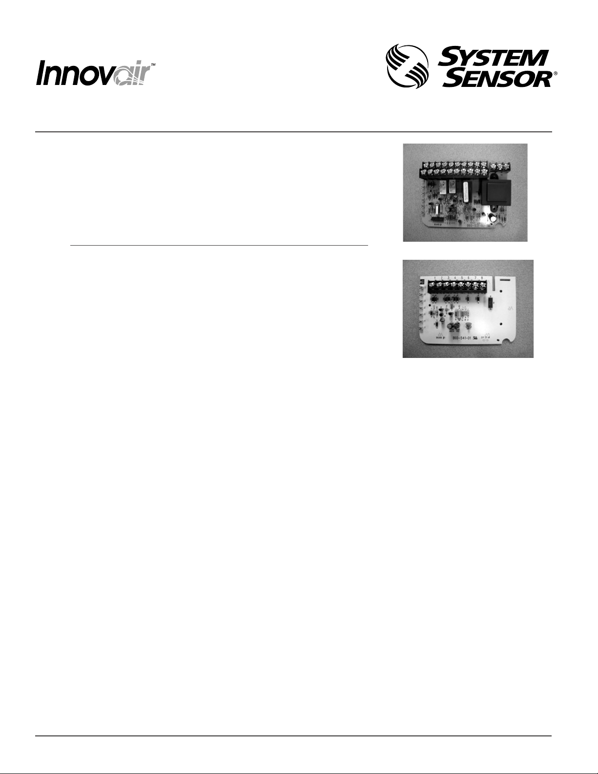
A5064: 4-Wire Power Board
A5061: 2-Wire Power Board
5. Remove the two power board mounting screws. Retain screws for installation of new board.
6. Pull gently on the board to remove it from the detector housing.
7. Align the board mounting features, holes, and interconnect terminals with the features on the duct smoke
detector housing.
8. Push the board into place.
9. Secure the board with the two board mounting screws.
10. Reconnect all wiring to the terminal block.
11. Apply power to the duct smoke detector.
12. Perform the detector checks as outlined in sections 6.2.1 and 6.2.2.1 of the Installation and Maintenance
Instructions to ensure proper detector operation. The tests performed must include:
A. Visually check to see the green power LED blinks once every ten seconds, indicating power to the duct
smoke detector.
B. Perform the magnet test to initiate an alarm condition. Reset the detector using the local reset button,
remote accessory, removing power or system control panel.
For additional assistance in this process or questions, please contact System Sensor Technical Service at
800-SENSOR2 (800-736-7672).
D100-71-00 2 I56-1359-01
© System Sensor 2004
 Loading...