

Page 1
INSTALLATION AND MAINTENANCE INSTRUCTIONS
WARNING
3825 Ohio Avenue, St. Charles, Illinois 60174
1-800-SENSOR2, FAX: 630-377-6495
CR-6 Six Relay Control Module
SPECIFICATIONS
Normal Operating Voltage: 15-32 VDC
Stand-By Current: 1.45 mA
Alarm Current: 32 mA (assumes all six relays have been switched once and all six LEDs solid on)
Temperature Range: 32°F to 120°F (0°C to 49°C)
Humidity: 10 to 93% Non-condensing
Dimensions: 6.8˝H × 5.8˝W × 1.0˝D
Accessories: BB-2 Cabinet; BB-6 Cabinet; CH-6 Chassis
Wire Gauge: 12-18 AWG
Relay Current: 30 mA/Relay Pulse (15.6 mS pulse duration) pulse under panel control
RELAY CONTACT RATINGS:
CURRENT RATING MAXIMUM VOLTAGE LOAD DESCRIPTION APPLICATION
2 A 25 VAC PF = 0.35 Non-coded
3 A 30 VDC Resistive Non-coded
2 A 30 VDC Resistive Coded
0.46 A 30 VDC (L/R = 20ms) Non-coded
0.7 A 70.7 VAC PF = 0.35 Non-coded
0.9 A 125 VDC Resistive Non-coded
0.5 A 125 VAC PF = 0.75 Non-coded
0.3 A 125 VAC PF = 0.35 Non-coded
I56-1798-009
www.systemsensor.com
All relay switch contacts are shipped in the standby state (open) state, but may have transferred to the activated (closed) state during shipping. To ensure that
the switch contacts are in their correct state, modules must be made to communicate with the panel before connecting circuits controlled by the module.
BEFORE INSTALLING
This information is included as a quick reference installation guide. If the
modules will be installed in an existing operational system, inform the operator and local authority that the system will be temporarily out of service.
Disconnect the power to the control panel before installing the modules. This
system contains static sensitive components. Always ground yourself with a
proper wrist strap before handling any circuits so that static charges are removed from the body. The housing cabinet should be metallic and suitably
grounded.
NOTICE: This manual should be left with the owner/user of this equipment.
GENERAL DESCRIPTION
The CR-6 Six Relay Control Module is intended for use in an intelligent alarm
system. Each module is intended for Form-C switching applications, which do
not require wiring supervision for the load circuit. A single isolated set of dry
relay contacts is provided for each module, which is capable of being wired
for either normally open or normally closed for each operation. Each module
has its own address. A pair of rotary code switches is used to set the address
of the first module from 01 to 94. The remaining modules are automatically assigned to the next five higher addresses. Provisions are included for disabling
a maximum of three unused modules to release the addresses to be used elsewhere. Each CR-6 module also has panel controlled green LED indicators. The
panel can cause the LEDs to blink, latch on, or latch off.
CONTENTS INCLUDE:
(6) 1 x 3 Terminal Blocks
(1) 1 x 4 Terminal Blocks
(2) 1¼˝ (32mm) Stand offs
(4) Machine Screws
(1) Shunt (NOTE: For the disable position, not more than one shunt shall be
installed at the same time)
(2) Nuts
COMPATIBILITY REQUIREMENTS
To ensure proper operation, this module shall be connected to a compatible
control panel only.
COMPONENTS
Following are descriptions of the CR-6 mounting frameworks. There are two
mounting options for CR-6 modules:
• Up to six CR-6 modules can be installed on a CH-6 in a BB-6 cabinet
• One or two CR-6 modules can be installed in a BB-2 cabinet
Chassis
The CH-6 chassis is used to mount CR-6 modules in a BB-6 cabinet. It accommodates up to six CR-6 modules in a single cabinet row three modules wide
and two modules deep.
D500-48-00 1 I56-1798-009
Page 2
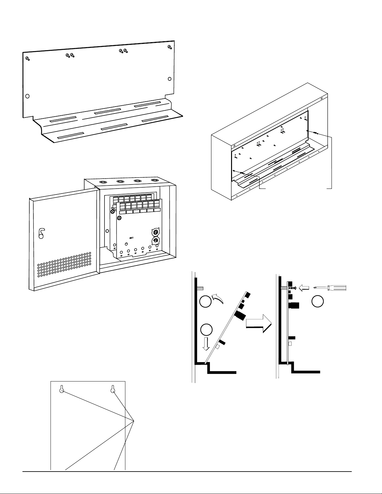
FIGURE 1: CH-6 CHASSIS
MOUNT WITH
SELF-THREADING SCREWS
TO BACK OF CABINET
BACKBOX
MOUNTING
HOLES
C0206-00
The BB-2 cabinet has a built-in chassis that will accommodate one or two
CR-6 modules.
FIGURE 2: BB-2 CABINET
4
3
5
2
6
1
7
BASE ADDRESS
0
8
15
9
NONE
THREE
ADDRESS
ONE
TWO
DISABLE
THREE
TWO
10
14
11
13
12
4
3
5
2
6
1
4
3
7
5
BASE ADDRESS
2
0
8
6
1
15
9
7
0
10
8
NONE
ONE
DISABLE
14
ADDRESS
11
13
12
9
4
3
5
2
6
1
7
0
8
9
In a clean, dry area, mount the backbox using the four holes provided in the
back surface of the cabinet.
2. Chassis Installation
The CH-6 chassis is mounted in the BB-6 cabinet. It is shipped with two selfthreading screws, which are used to fasten the chassis to the back wall of the
cabinet (see Figure 4).
FIGURE 4: MOUNTING THE CH-6 CHASSIS
C0236-00
The BB-2 cabinet comes with the chassis already installed, so no mounting
is necessary.
3. Module Installation
There are two methods for installing a module in the rear position of a chassis. Method one is for installation of a rear module only, when no module will
be installed in front of it. Refer to Figure 5 for instructions. Method two is for
installation of a rear module when another module will be installed in the
chassis position in front of it. Refer to Figures 6a and 6b for method two. All
necessary screws and standoffs are supplied with the modules.
FIGURE 5: INSTALLATION OF REAR MODULE ONLY, METHOD ONE
C0234-*00
The front CR-6 module positions of each chassis are offset below the rear CR-6
module positions so that all of the status indicators are visible.
Cabinets
A BB-6 cabinet will house the CH-6 chassis with up to six CR-6 modules installed on it.
The BB-2 cabinet houses one or two CR-6 modules on the internal chassis that
is part of the cabinet. Refer to cabinet installation documents for dimensions.
INSTALLATION STEPS
1. Cabinet Mounting
FIGURE 3: TYPICAL MOUNTING HOLE LOCATIONS
C0235-00
2
3
1
C0243-00
Step 1: Insert the bottom of the CR-6 module down into a rear slot
on the chassis.
Step 2: Carefully swing the upper edge of the board back towards the back of
the chassis until it touches the two standoffs.
Step 3: Align two 4-40 screws with the two standoffs and tighten.
Step 4: Address and wire the modules according to the instructions in
this manual.
The steps in Figures 6a and 6b describe and illustrate module installation
when the rear chassis position and the position in front of it will be filled.
Front position installation is possible only if the rear position is filled with an
input/output module.
D500-48-00 2 I56-1798-009
Page 3

FIGURE 6A: INSTALLATION OF CR-6 MODULE IN A REAR CHASSIS
POSITION, METHOD TwO
1
C0244-00
Step 1: Insert the bottom edge of the CR-6 module down into a rear slot of
the chassis.
Step 2: Carefully swing the upper edge of the board towards the back of the
chassis until it touches the short standoff attached to the chassis.
St ep 3: Align the long standoff with the short standoff and tighten.
FIGURE 6B: INSTALLATION OF CR-6 MODULE IN FRONT CHASSIS
POSITION
wIRING
NOTE: Power must not be applied to the unit when changing functionality of
the shunts.
NOTE: All wiring must conform to applicable local codes, ordinances, and
regulations.
1. Install module wiring in accordance with the job drawings and appropriate wiring diagrams.
2. Make electrical connections by stripping approximately 1/4˝ (6.35mm) of
insulation from the end of the wire sliding the bare end of the wire under
the clamping plate, and tightening the clamping plate screw.
3. Set the address on the modules per the job drawing. Use the rotary code
switches to set the address of the first
remaining modules are automatically assigned to the next five higher
addresses. For example, if the base address switch is set to 28, the next
five modules will be addressed to 29, 30, 31, 32, and 33. DO NOT set
the lowest address above 94, as the other modules will be assigned to
nonexistent addresses.
4. A shunt is provided to disable a maximum of three unused modules.
Modules are disabled from the highest address and work downward. If
two modules are disabled, the lowest four addresses will be functional,
while the highest two will be disabled. For example, if the shunt for Address Disable is placed on “two” and the base address switch is set to 28,
the modules will be assigned to 28, 29, 30 and 31.
module (between 01 and 94). The
3
2
1
C0245-00
Step 1: Insert the bottom edge of the CR-6 module down into a front slot of
the chassis.
Step 2: Carefully swing the upper edge of the board towards the back of the
chassis until it touches the 11/4˝ (31.75mm) standoffs installed on the
rear module.
Step 3: Align two 4-40 screws with the two standoffs and tighten.
Step 4: Address and wire the modules according to the instructions in
this manual.
D500-48-00 3 I56-1798-009
Page 4

0
1
2
3
4
5
6
7
8
9
N.C.
N.O.
COMMON
ADDRESS 5
N.C.
N.O.
COMMON
ADDRESS 4
N.C.
N.O.
COMMON
ADDRESS 3
N.C.
N.O.
COMMON
ADDRESS 2
N.C.
N.O.
COMMON
ADDRESS 1
N.C.
N.O.
COMMON
ADDRESS 0
SLC
BASE ADDRESS
ADDRESS
DISABLE
NONE
ONE
TWO
THREE
6.8"
5.8"
FROM PANEL
OR PREVIOUS DEVICE
SIGNAL LINE CIRCUIT
32 VDC MAX.
TWISTED PAIR
IS RECOMMENDED
TO NEXT
DEVICE
–
+
–
+
–
+
NC
NO
COMMON
RELAY CONNECTIONS
0
1
2
3
4
5
6
7
8
9
STATUS
INDICATORS
FIGURE 7: wIRING AND PROGRAMMING THE CR-6 MODULE
NOTES:
• The relay contacts on the CR-6 may be connected to either a powerlimited or non power-limited source, this wiring must remain separated
by at least 1/4˝ (6.35 mm) from all power-limited wiring.
• Power-limited circuits must employ type FPL, FPLR, or FPLP cable as
required by Article 760 of the NEC.
• For easier wiring, assign all power-limited wiring to one side rather than
alternating with non power-limited.
C205-01
THREE-YEAR LIMITED wARRANTY
System Sensor warrants its enclosed air duct smoke detector to be free from defects in
materials and workmanship under normal use and service for a period of three years
from date of manufacture. System Sensor makes no other express warranty for this air
duct smoke detector. No agent, representative, dealer, or employee of the Company has
the authority to increase or alter the obligations or limitations of this Warranty. The
Company’s obligation of this Warranty shall be limited to the replacement of any part of
the air duct smoke detector which is found to be defective in materials or workmanship
under normal use and service during the three year period commencing with the date of
manufacture. After phoning System Sensor’s toll free number 800-SENSOR2 (736-7672)
for a Return Authorization number, send defective units postage prepaid to: System
This device complies with part 15 of the FCC Rules. Operation is subject to the following two conditions: (1) This device may not cause harmful interference, and (2) this device must
accept any interference received, including interference that may cause undesired operation.
NOTE: This equipment has been tested and found to comply with the limits for a Class B digital device, pursuant to Part 15 of the FCC Rules. These limits are designed to provide
reasonable protection against harmful interference in a residential installation. This equipment generates, uses and can radiate radio frequency energy and, if not installed and used
in accordance with the instructions, may cause harmful interference to radio communications. However, there is no guarantee that interference will not occur in a particular installation. If this equipment does cause harmful interference to radio or television reception, which can be determined by turning the equipment off and on, the user is encouraged to
try to correct the interference by one or more of the following measures:
– Reorient or relocate the receiving antenna.
– Increase the separation between the equipment and receiver.
– Connect the equipment into an outlet on a circuit different from that to which the receiver is connected.
– Consult the dealer or an experienced radio/TV technician for help.
FCC STATEMENT
Sensor, Returns Department, RA #__________, 3825 Ohio Avenue, St. Charles, IL 60174.
Please include a note describing the malfunction and suspected cause of failure. The
Company shall not be obligated to replace units which are found to be defective because
of damage, unreasonable use, modifications, or alterations occurring after the date of
manufacture. In no case shall the Company be liable for any consequential or incidental
damages for breach of this or any other Warranty, expressed or implied whatsoever, even
if the loss or damage is caused by the Company’s negligence or fault. Some states do not
allow the exclusion or limitation of incidental or consequential damages, so the above
limitation or exclusion may not apply to you. This Warranty gives you specific legal
rights, and you may also have other rights which vary from state to state.
D500-48-00 4 I56-1798-009
©2011 System Sensor
 Loading...