

Page 1
INSTALLATION AND MAINTENANCE INSTRUCTIONS
LIVING
ROOM
BEDROOM BEDROOM
BEDROOM
KITCHEN
TO
BR
CLOSED
DOOR
BASEMENT
GARAGE
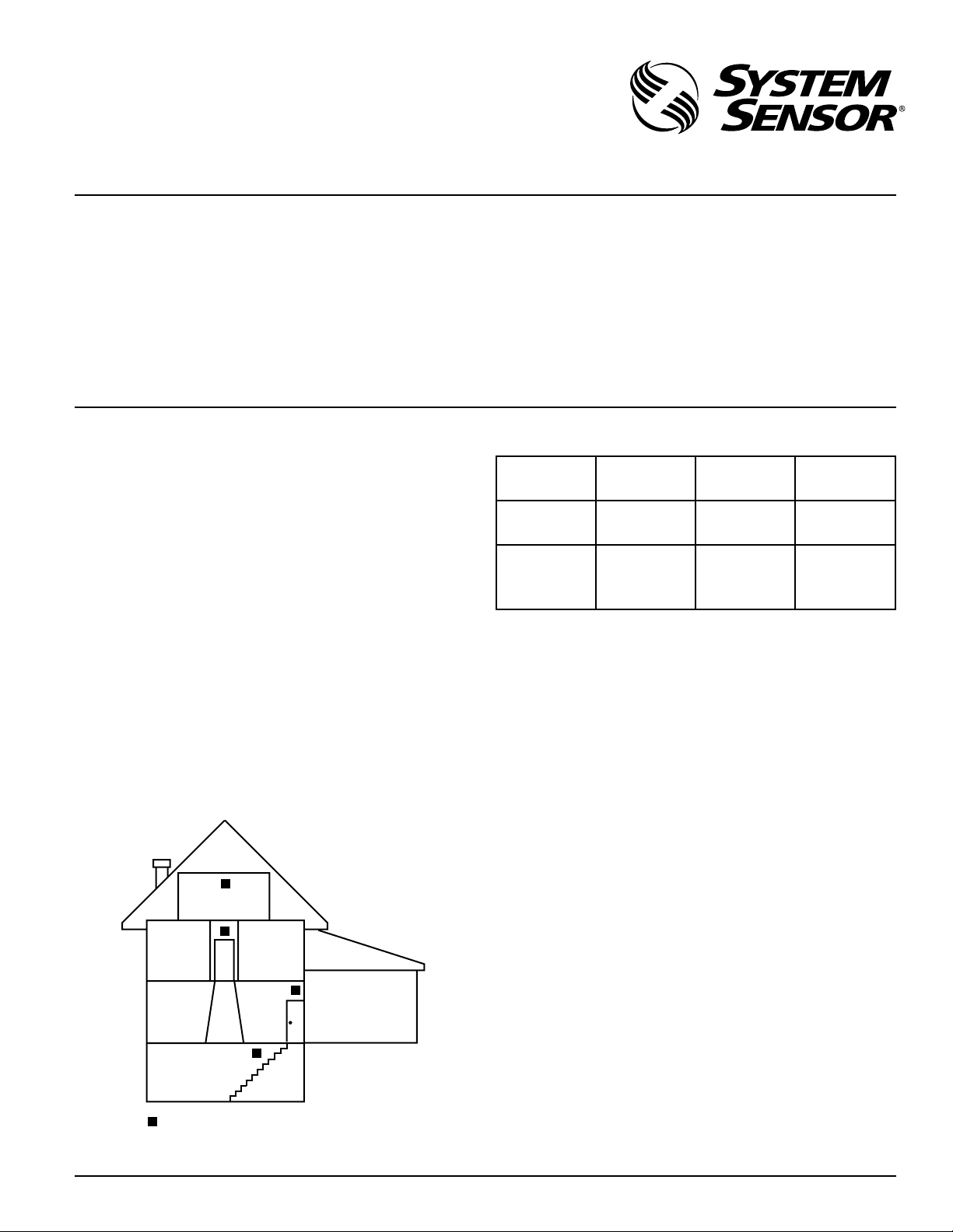
CARBON MONOXIDE ALARM
LOCATION FOR MULTI-LEVEL RESIDENCE
–
CO1224
Carbon Monoxide Detector
Specifications
Electrical Specifications
System Voltage
Nominal: 12/24 VDC
Min: 10 VDC
Max: 33 VDC
Avg. Standby Current: 20 mA
Max Alarm Current: 40 mA (75 mA test)
Alarm Contact Ratings: 30 VDC @ 0.5 A
Trouble Contact Ratings: 30 VDC @ 0.5 A
Audible Signal (temp 4 tone): 85 dBA min. in alarm (at 10ft)
Max. Start-up Capacitance: 20 uF
NOTICE: This manual shall be left with the owner/user of
this equipment.
WARNING: This product is intended for use in ordinary indoor
locations of dwelling units, including homes, residential buildings,
hotels, schools, dormitories, and day care centers. It is not intended
for use in industrial factories or commercial parking garages.
General Description
• Listed to UL standard 2075
• 4 wire, system monitored
• Local sounder
• Low current draw
• Alarm relay, Form C
• Trouble relay, Form A
• Dual LED’s
• Test/Hush button
• SEMS wiring terminals
• Mount to single gang electrical box or surface mount to wall
or ceiling
• Optional drywall anchors included
Figure 1. Alarm Location Diagram:
C0295-00
3825 Ohio Avenue, St. Charles, Illinois 60174
1-800-SENSOR2, FAX: 630-377-6495
www.systemsensor.com
Physical Specifications
Operating Temperature Range: 0
° to 40°C (32° to 104°F)
Operating Humidity Range: 22 – 90% %RH
Length: 5.1˝
Width: 3.3˝
Height: 1.3˝
Weight: 7 oz
Wire Gauge Acceptance: 14-22 AWG
Table 1. Detector Operation Modes:
Operation
Mode
Normal
(standby)
Alarm -
*Temp 4 pattern is repeated pattern of four short indications followed by a five second pause.
When the detector has been in alarm for 30 minutes the alarm
signal will be given once every minute.
If ambient conditions return to normal, the detector will self-re
store out of alarm and into Normal (standby) mode.
Hush feature: If required, the audible alarm can be silenced for
5 minutes by pushing the button marked “Test/Hush”. The red
alarm light will continue to flash in temp-4 pattern. If carbon
monoxide is still present after the 5 minute hush period, the au
dible alarm will sound. The hush facility will not operate at levels
above 350 ppm (parts per million) carbon monoxide.
Trouble feature: When the sensor supervision is in a trouble condition (such as a sensor that has been tampered with), the detec
tor will send a trouble signal to the panel. The detector must then
be replaced.
End of Life Timer feature: When the detector has reached the
end of its life, the trouble contact will open. This indicates that
the CO sensor inside the detector has passed the end of its life
and must be replaced. This detector’s lifespan is approximately
six years from the date of manufacture. Refer to Detector Replace
ment on page 3.
Per UL 2075, it is mandatory that a trouble signal be sent to the
panel upon CO cell trouble or cell end of life. Refer to Figure 4
for wiring of the trouble relay.
Green
LED
Blink 1
per minute
Red
LED
- -
Blink in
temp 4*
pattern
Sounder
Sound in
temp 4*
pattern
-
-
-
-
D250-03-00 1 I56-2874-001
Page 2
Installation Guidelines
WARNING
CAUTION
In a wall location, the detector should be at least as high as a light
switch, and at least six inches from the ceiling. In a ceiling loca
tion, the detector should be at least 12 inches from any wall.
Where to install, ideally:
• Within 10 feet of all sleeping areas
• Inside the bedroom if it contains a fuel burning appliance
• On every floor of the building
• Ideally, install in any room that contains a fuel burning appliance
• If the appliance in the room is not normally used, such as the
boiler room, the detector should be placed just outside the
room so the alarm can be heard more easily
Where
NOT to install, ideally:
• Detectors operate best if not installed within 10 feet of any
cooking appliance
• Directly above a sink, cooker, stove or oven
• Next to a door or window that would be affected by drafts i.e.
extractor fan or air vent
• Outside
• Do not install in any environment that does not comply with
the detector’s environmental specifications
• In or below a cupboard
• Where air flow would be obstructed by curtains or furniture
• Where dirt or dust could collect and block the sensor
• Where it could be knocked, damaged, or inadvertently removed
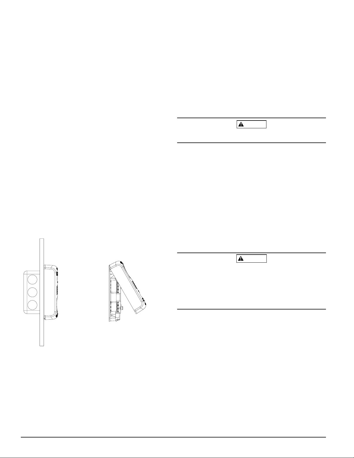
Mounting
The CO1224 can be wall- or ceiling-mounted:
1. To a single gang box, or
2. Direct mount to wall or to ceiling using drywall fasteners.
Figure 2. Mounting of Detector:
The screw terminals in the mounting base will accept 14-22 gauge
wire. Wire connections are made by stripping approximately
of insulation from the end of the feed wire, inserting it into the
proper base terminal, and tightening the screw to secure the wire
in place. Do not put wires more than 2 gauge apart under the
same clamping plate.
WARNING: This product does not have a local audible trouble
signal, and may fail without supervision if trouble loop remains
unconnected.
WARNING: Gas detectors on a zone that is bypassed may not signal
a trouble condition. Do not bypass zones used for gas detectors.
Wiring diagrams located on page 4, Figure 4.
Installation
Remove power from alarm control unit or initiating device circuits
before installing detectors.
1. Using a small, flat head screw driver, push in the small tab
located on the underside of the detector. Once the snap is
loosened, lift the bottom end of the cover up and unhinge the
top to remove the cover.
2. Wire the detector base screw terminals per
3. Screw the base of the detector onto a single gang electrical
box, or to the surface of the wall or ceiling. Use the hardware
included in the packaging.
4. Hinge the top portion of the cover onto the base; with the cover
at a 45 degree angle, fit the hinges into the slots of the base.
5. Push the unhinged bottom portion of the cover down until it
snaps into place.
6. After all detectors have been installed, apply power to the
alarm control unit.
7. Test each detector as described in Testing.
8. Notify the proper authorities that the system is in operation.
Figure 4.
1
/4˝
C0296-00
C0301-00
Wiring Installation Guidelines
All wiring must be installed in compliance with the NFPA 70, National Electrical Code, applicable state and local codes, and any spe
cial requirements of the local Authority Having Jurisdiction (AHJ).
Proper wire gauges should be used. The conductors used to con
nect carbon monoxide detectors to the alarm control panel and
accessory devices should be color-coded to reduce the likelihood
of wiring errors. Improper connections can prevent a system from
responding properly in the event of a CO.
Airborne dust particles can enter the detector. System Sensor recommends the removal of detectors before beginning construction
or any other dust producing activity.
Carbon monoxide detectors are not to be used with detector
guards unless the combination has been evaluated and found
suitable for that purpose.
Testing
Detector must be tested after installation.
NOTE: Before testing, notify the proper authorities that maintenance is being performed and the system will be temporarily out
of service. Disable the zone or system undergoing maintenance to
prevent any unwanted alarms.
Ensure proper wiring and power is applied. After power up, allow
80 seconds for the detector to stabilize before testing.
Test the CO1224 detector as follows:
-
1. A test button is located on the detector housing (See
2. Use the tip of your finger to press and hold the test button.
-
3. If the sounder beeps and the LED’s light up after 1-4 seconds,
the detector is operational.
Figure 3).
D250-03-00 2 I56-2874-001
Page 3

Figure 3. Test Button Location and Operation:
Test/ Hush
Button
C0298-00
If a detector fails the above test method, its wiring should be checked.
If the detector still fails after rewiring, it should be replaced.
The manufacturer cannot recommend a specific agent with
which to test the detector.
Testing the detector will activate the alarm relay and send a
signal to the panel.
CAUTION: This carbon monoxide detector is designed for indoor
use only. Do not expose to rain or moisture. Do not knock or
drop the detector. Do not open or tamper with the detector as
this could cause malfunction. The detector will not protect against
the risk of carbon monoxide poisoning if not properly wired. The
detector will only indicate the presence of carbon monoxide gas at
the sensor. Carbon monoxide gas may be present in other areas.
This carbon monoxide detector is NOT:
• Designed to detect smoke, fire or any gas other than car
bon monoxide
• To be seen as a substitute for the proper servicing of fuel-burn
ing appliances or the sweeping of chimneys.
• To be used on an intermittent basis, or as a portable alarm for
the spillage of combustion products from fuel-burning appli
ances or chimneys.
Carbon monoxide gas is a highly poisonous gas which is released
when fuels are burnt. It is invisible, has no smell and is therefore
impossible to detect with the human senses. Under normal condi
tions in a room where fuel burning appliances are well maintained
and correctly ventilated, the amount of carbon monoxide released
into the room by appliances should not be dangerous.
Symptoms of carbon monoxide poisoning: Carbon monoxide
bonds to the hemoglobin in the blood and reduces the amount
of oxygen being circulated in the body. The following symptoms
are related to carbon monoxide poisoning and should be discussed
with all members of the household:
Mild exposure: Slight headache, nausea, vomiting, fatigue
•
(often described as “flu-like” symptoms).
•
Medium exposure: Sever throbbing headache, drowsiness,
confusion, fast heart rate.
Extreme exposure: Unconsciousness, convulsions, cardio re
•
spiratory failure, death.
Many causes of reported carbon monoxide poisoning indicate that
while victims are aware that they are not well, they become so dis
oriented that they are unable to save themselves by either exiting
the building or calling for assistance.
Also young children and pets may be the first to be affected.
What to do if the carbon monoxide detector goes into alarm:
Immediately move to a spot where fresh air is available, preferably
outdoors. Find a phone in an area where the air is safe and call
your security service provider. Tell your provider the detector alarm
status, and that you require professional assistance in ridding your
home of the carbon monoxide.
IMPORTANT: This detector should be tested and maintained
regularly following National Fire Protection Association (NFPA)
720 requirements.
Maintenance
Occasionally clean the outside casing with a cloth. Ensure that the
holes on the front of the alarm are not blocked with dirt and dust.
Do not paint, and do not use cleaning agents, bleach, or polish
on the detector.
Detector Replacement
This detector is manufactured with a long-life carbon monoxide
sensor. Over time the sensor will lose sensitivity, and will need to
be replaced with a new System Sensor carbon monoxide detector.
This detector’s lifespan is approximately six years from the date
of manufacture.
Periodically check the detector’s replacement date. Remove the
detector cover and refer to the sticker placed on the inside of
the detector. The sticker will indicate the date that the detector
should be replaced.
-
This detector is also equipped with a feature that will open the
trouble relay once it has reached the end of its useful life. If this
occurs, it is time to replace the detector.
NOTE: Before replacing the detector, notify the proper authorities
that maintenance is being performed and the system will be tempo
rarily out of service. Disable the zone or system undergoing main
tenance to prevent any unwanted alarms. Dispose of detector in
accordance with any local regulations.
-
-
-
-
-
D250-03-00 3 I56-2874-001
Page 4

Figure 4. Wiring Diagram:
POSITIVE
NEGATIVE
TROUBLE
TROUBLE
NORMALLY
CLOSED
NORMALLY
OPEN
COMMON
}
POWER
}
TROUBLE
RELAY
ALARM
RELAY
NON-RESETTABLE PWR
CO ZONE
UL LISTED
PANEL
+
−
ALARM
INITIATION
CONTACTS
EOL RESISTOR
SPECIFIED BY PANEL
MANUFACTURER
C
NO
T T
+ −
CLOSED WITH
POWER APPLIED
AND NO FAULT
DETECTED
SINGLE UNIT, SINGLE ZONE, 4 CONDUCTOR CABLE
NON-RESETTABLE PWR
CO ZONE
UL LISTED
PANEL
+
−
SUPERVISORY TROUBLE CONTACTS
ALARM
INITIATION
CONTACTS
ALARM
INITIATION
CONTACTS
FIRST CO1224
DETECTOR
IN LOOP
LAST CO1224
DETECTOR
IN LOOP
EOL RESISTOR
SPECIFIED BY PANEL
MANUFACTURER
C
NO
C
NO
T T T T
+ −
+ −
CLOSED WITH
POWER APPLIED
AND NO FAULT
DETECTED
MULTIPLE UNIT, SINGLE ZONE, 6 CONDUCTOR CABLE
CAUTION
S0313-00
It should be noted the installation, operation, testing and maintenance of the CO1224 is different than System Sensor conventional
4-wire smoke detectors, such as the i3 Series. Below are specific
installation requirements for the CO1224:
* Connect to a non-resettable power supply
* Connect to a non-fire zone: Per NFPA 720 section 5.3.7.2 the CO1224
shall not be connected to a zone that signals a fire condition
* Per NFPA 720 section 5.3.7, do not connect the CO1224 on a zone with
other fire or intrusion initiating devices - i.e. do not connect on the
same zone as smoke detectors
* Wiring of the trouble relay is mandatory: Per UL Standard 2075 section
17.1.1 a detector shall send a trouble signal to the control panel upon
an open circuit, a ground fault, sensor removal or sensor end of life
* If wiring one CO1224 per zone: Use 4 conductors
* If wiring multiple CO1224 detectors per zone: Use 4 conductors from
panel to first CO1224, then use 6 conductors from the second CO1224
to other detectors on the zone
S0314-00
Input powered (12 or 24 VDC) from UL Listed Fire/Burg Control Panel (Class 2).
Please refer to inser t for the limitations of Carbon Monoxide Detectors
FCC Statement
This device complies with part 15 of the FCC Rules. Operation is subject to the following two conditions: (1) This device may not cause harmful interference, and (2) this device
must accept any interference received, including interference that may cause undesired operation.
NOTE: This equipment has been tested and found to comply with the limits for a Class B digital device, pursuant to Part 15 of the FCC Rules. These limits are designed to provide reasonable protection against harmful interference in a residential installation. This equipment generates, uses and can radiate radio frequency energy and, if not installed
and used in accordance with the instructions, may cause harmful interference to radio communications. However, there is no guarantee that interference will not occur in a
particular installation. If this equipment does cause harmful interference to radio or television reception, which can be determined by turning the equipment off and on, the user
is encouraged to try to correct the interference by one or more of the following measures:
– Reorient or relocate the receiving antenna.
– Increase the separation between the equipment and receiver.
– Connect the equipment into an outlet on a circuit different from that to which the receiver is connected.
– Consult the dealer or an experienced radio/TV technician for help.
Three-Year Limited Warranty
System Sensor warrants its enclosed product to be free from defects in
materials and workmanship under normal use and service for a period
of three years from date of manufacture. System Sensor makes no other
express warranty for the enclosed product. No agent, representative,
dealer, or employee of the Company has the authority to increase or alter
the obligations or limitations of this Warranty. The Company’s obliga
tion of this Warranty shall be limited to the replacement of any part of
the product which is found to be defective in materials or workmanship under normal use and service during the three year period commencing with the date of manufacture. After phoning System Sensor’s
toll free number 800-SENSOR2 (736-7672) for a Return Authorization
number, send defective units postage prepaid to: System Sensor, Returns
D250-03-00 4 I56-2874-001
©2006 System Sensor
Department, RA #__________, 3825 Ohio Avenue, St. Charles, IL 60174.
Please include a note describing the malfunction and suspected cause
of failure. The Company shall not be obligated to replace units which
are found to be defective because of damage, unreasonable use, modi
fications, or alterations occurring after the date of manufacture. In no
case shall the Company be liable for any consequential or incidental
damages for breach of this or any other Warranty, expressed or implied
whatsoever, even if the loss or damage is caused by the Company’s
negligence or fault. Some states do not allow the exclusion or limitation of incidental or consequential damages, so the above limitation or
exclusion may not apply to you. This Warranty gives you specific legal
rights, and you may also have other rights which vary from state to state.
S0300-01
-
 Loading...