

Page 1
INSTALLATION AND MAINTENANCE INSTRUCTIONS
SpectrAlert Selectable Output
CH24 Series Wall Chime/Strobes
3825 Ohio Avenue, St. Charles, Illinois 60174
1-800-SENSOR2, FAX: 630-377-6495
www.systemsensor.com
for Fire Protective Signaling Systems
For use with the following models: CH24 and CH24W
U.S. Patent Nos. 5,593,569; 5.914,665; 5,850,178; 5,598,139; 6,049,446; 6,127,935
Specifications: Chime
Mechanical
Input Terminals: 12 to 18 AWG (3.31 to 0.82 mm2)
Overall Dimensions: 6.9″ × 5.0″
Electrical
Voltage Input: DC or Full-Wave Rectified 8-33 volts
Operating
Temperature Range: 32° to 120°F (0° to 49°C)
Listings: UL S4011 Private Mode (Chime/Strobe),
UL S5512 (Strobe)
Note for Strobes: Do not exceed 1) 16-33 Voltage range limit, 2) Maximum number of 70 strobe lights when connecting the MDL Sync module with a maximum line impedance of 4 Ohms per loop and 3) Maximum line impedance as required by the fire alarm control manufacturer.
NOTICE: This manual shall be left with the owner/user of this
equipment.
General Description
The SpectrAlert CH24 series strobe can be installed in systems
using 24-volt panels having DC or full-wave rectified (FWR)
power supplies. The strobes can also be installed in applications
requiring synchronization (MDL required) or applications that do
not require synchronization (no module required). Please note
that the chime section is not synchronizable with the MDL.
The SpectrAlert CH24 series chime/strobes are designed to meet
the requirements of most agencies governing these devices,
including: NFPA, ADA, The National Fire Alarm Code, UL, CSFM,
MEA. Also, check with your local Authority Having Jurisdiction
for other codes or standards that may apply.
Note: The SpectrAlert CH24 Series Chime/Strobe must be
powered from a non-coded power supply. This appliance is not intended for use with a coded power supply.
Fire Alarm Considerations
Temporal and Non-Temporal Coded Signals:
The American National Standards Institute and the National
Fire Alarm Code require that all horns used for building evacuation installed after July 1, 1996, must produce Temporal Coded
Signals. Signals other than those used for evacuation purposes do
not have to produce the Temporal Coded Signal.
Power Supply Considerations For Strobes
Panels typically supply DC filtered voltage or FWR (full-wave
rectified) voltage. The system design engineer must calculate the
number of units used in a zone based on the type of panel sup-
Specifications: Strobe
Voltage Range: Regulated 24 DC/FWR
Operational Voltage Range: 16-33 Volts
Synchronous Applications
with MDL Module: 17-33 Volts
Flash Rate: 1 flash per second
Selectable Light Outputs: All candelas are selectable via a
manual slide switch. 15/75 is listed at 15 candela per UL 1971 but
will provide 75 candela on axis (straight ahead). 15, 30, 75, or 110
are rated for that candela.
ply. Be certain the sum of all the device currents do not exceed
the current capability of the panel. Calculations are based on
using the device current found in Table 3 and must be the current
specified for the type of panel power supply used.
Wire Sizes
The designer must be sure that the last device on the circuit has
sufficient voltage to operate the device within its rated voltage.
When calculating the voltage available to the last device, it is
necessary to consider the voltage drop due to the resistance of the
wire. The thicker the wire, the less the voltage drop. Generally, for
purposes of determining the wire size necessary for the system,
it is best to consider all of the devices as “lumped” on the end of
the supply circuit (simulates “worst case”).
Typical wire size resistance:
18 AWG solid: Approximately 8 ohms/1,000 ft.
16 AWG solid: Approximately 5 ohms/1,000 ft.
14 AWG solid: Approximately 3 ohms/1,000 ft.
12 AWG solid: Approximately 2 ohms/1,000 ft.
Example: Assume you have 10 devices on a zone and each
requires 50 mA average and 2000 Ft. of 14 AWG wiring (total
length=outgoing + return). The voltage at the end of the loop
is 0.050 amps per device × 10 devices × 3 ohms/1,000 ft. × 2000
ft =3 volts drop.
The same number of devices using 12 AWG wire will produce only
2 volts drop. The same devices using 18 AWG wire will produce
8 volts drop. Consult your panel manufacturer’s specifications, as
well as SpectrAlert’s operating voltage range to determine acceptable voltage drop.
Note: If class “A” wiring is installed, the wire length may be up to
4 times the single wire length in this calculation.
D900-24-00 1 I56-0936-003R
Page 2
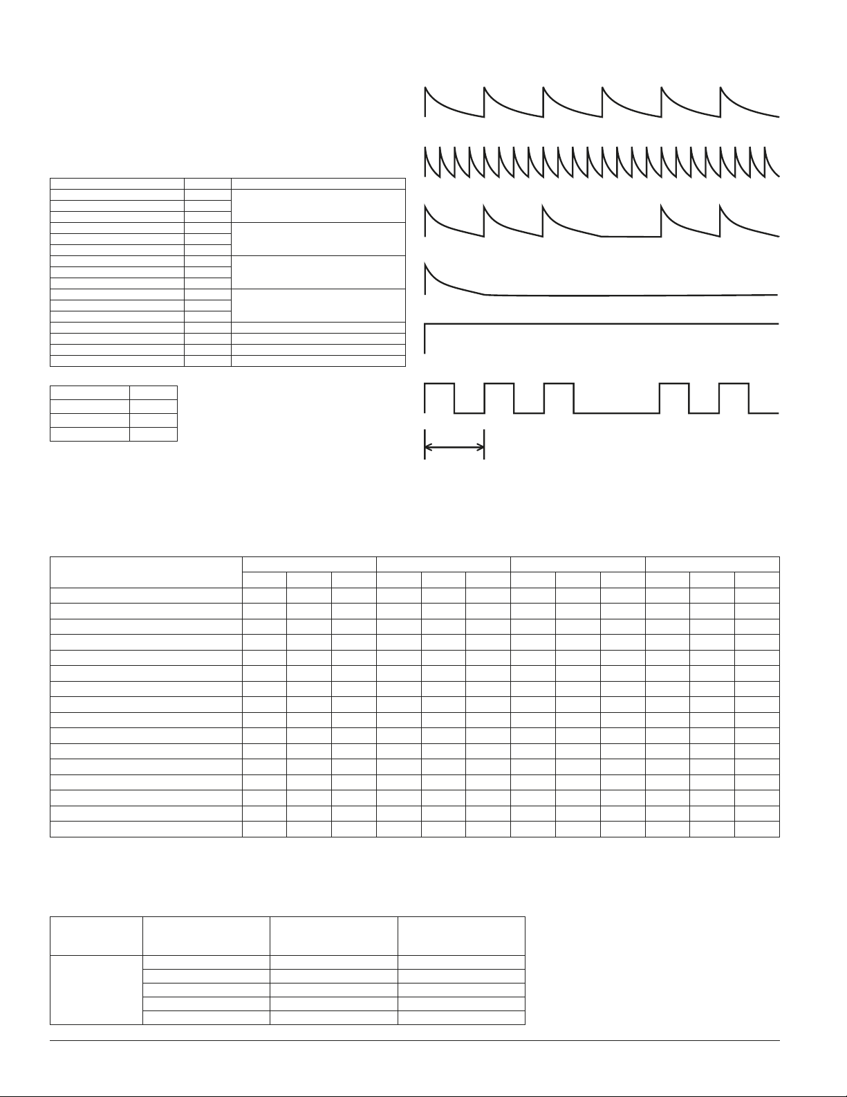
Chime Selection
Repeating 1-Second Chime
Repeating 1/4-Second Chime
Temporal 3 Chime
Single Stroke Chime
Continuous 500Hz Electromechanical and 3kHz Electromechanical
Temporal 500Hz Electromechanical and 3kHz Electromechanical
Scale:
1 second
Chimes are factory set for high volume, 1.0K repeating 1 second
chime. Tones may be selected by making the appropriate settings
on the DIP Switch located on the printed circuit board. The settings required for the available tone options are as follows:
Table 1: SpectrAlert Chime Switch Settings
Switch 1=on 0=off
1 2 3 4 Hz Type
1 1 1 1 1.2k
Repeating 1-Second Chime1 0 1 1 1.0k
1 1 0 1 0.8k
1 0 0 1 1.2k
Repeating 1/4-Second Chime1 1 1 0 1.0k
1 0 1 0 0.8k
1 1 0 0 1.2k
Temporal 3 Chime1 0 0 0 1.0k
0 1 1 1 0.8k
0 0 1 1 1.2k
Single Stroke Chime0 1 0 1 1.0k
0 0 0 1 0.8k
0 1 1 0 3.0k Electromechanical Continuous
0 0 1 0 3.0k Electromechanical Temporal 3
0 1 0 0 0.5k Electromechanical Continuous
0 0 0 0 0.5k Electromechanical Temporal 3
Volume Switch
5 6
0 0 LOW
1 0 MED
1 1 HIGH
SpectrAlert Chime Tones
SpectrAlert Electronic Chime Current Draw*
8-33VDC: 10–61mA
*Average current draw varies with tones selected. Current ratings per System Sensor testing at 12VDC and 24VDC. Add current values when connecting in parallel.
Table 2: SpectrAlert Electronic Chime Sound Output Guide
Tone
1.2K Repeating 1-Second Chime 51 52 55 53 54 56 57 61 52 59 61 64
1.0K Repeating 1-Second Chime 48 50 54 51 52 54 54 57 60 57 60 62
0.8K Repeating 1-Second Chime 47 47 53 49 51 52 53 55 58 55 58 60
1.2K Repeating 1/4-Second Chime 53 54 58 55 57 59 59 61 64 61 63 66
1.0K Repeating 1/4-Second Chime 49 50 54 51 53 54 55 57 60 57 59 62
0.8K Repeating 1/4-Second Chime 48 50 53 50 52 53 54 56 59 56 58 61
1.2K Temporal 3 Chime 51 52 56 52 54 55 55 57 61 58 60 63
1.0K Temporal 3 Chime 48 49 54 49 51 51 53 55 58 55 57 60
0.8K Temporal 3 Chime 46 47 51 48 50 51 52 54 57 54 56 59
1.2K Single Stroke Chime 52 53 58 52 54 56 56 58 62 58 60 64
1.0K Single Stroke Chime 47 48 53 50 51 59 53 55 58 56 58 62
0.8K Single Stroke Chime 47 48 53 49 50 52 54 56 60 56 59 61
3.0K Continuous Electromechanical 56 57 61 59 60 67 65 68 70 68 70 74
3.0K Temporal Electromechanical 51 52 56 53 54 61 56 59 62 58 60 64
0.5K Continuous Electromechanical 48 49 53 51 52 56 54 57 60 56 55 61
0.5K Temporal Electromechanical 45 47 51 47 49 53 51 52 58 52 54 60
Low Med. High Low Med. High Low Med. High Low Med. High
NOTE: Factory default setting is 1.0K Repeating 1 Second Chime set at High volume.
Table 3: Strobe Current Draw Measurements
NOTE: All models were only tested at the 16-33 Volt-FWR/DC limits. This does not include the 80% low-end or 110% high-end voltage limits.
Model No. Candela Setting
CH24MC
Chime/Strobe
15 84 59
15/75 74 69
30 93 90
75 158 160
110 208 209
8 Volts 12 Volts 24 Volts 33 Volts
FWR Operating
Current–Strobe
(mA RMS)
DC Operating
Current–Strobe
(mA RMS)
D900-24-00 2 I56-0936-003R
Page 3

Mounting
LOCKING RIB SLOT
DRYWALL SCREWS
(OPTIONAL)
4-INCH BACK BOX
MUD RING
8-32 SCREW
6-32 SCREW
6-32 SCREW
8-32 SCREW
BBS-CHS
INSERT
SCREWDRIVER
TO REMOVE
LOCKING RIB
When strobe is on the
right, mount chime/strobe
with 6-32 screws inserted
into the holes on the left
of the mud ring.
LEFT
RIGHT
When strobe is on the
left, mount chime/strobe
with 6-32 screws inserted
into the holes on the right
of the mud ring.
LEFT
RIGHT
4-INCH BACK BOX
MUD RING
8-32 SCREW
6-32 SCREW
Reversible strobe module
Should the back box be located near an obstruction such as a
doorway, the strobe module is field-reversible (Fig. 1).
A0166-00
To reverse the strobe module: insert screwdriver, as shown in
Fig. 3, to unlock snap. While pushing in the screwdriver, pull
back on the strobe module. Hinge the strobe module, disengage
the Locking Rib and lift the module away from the mounting
plate. Turn the module so that it is upside down from its original
position, re-insert the module into the mounting plate (be sure
to insert the Locking Rib into the slot), and press the module
into the mounting plate. The strobe module will make a “click”
when it has locked into place. Turn the entire assembly so that
the lens/reflector is on the bottom, as shown. The unit can now
be mounted.
Flush mount back box
The chime/strobe can be flush mounted on a 4″×4″×11⁄2″ back box
(Fig. 2) as follows:
A. For the 4″×4″, mount the mud plate (provided) using the 8-32
pan head screws. Make sure the mud plate is mounted vertically, as shown.
B. Mount the chime/strobe using the 6-32 oval head screws. The
chime/strobe shall be mounted on the left side of the mud
ring. The 6-32 screws shall be inserted into the holes on the
mud ring that are opposite that of the strobes; i.e., when the
strobe is on the right, screws into the left side of the mud ring,
and vice versa. See Figure 1.
NOTE: Two drywall screws (provided) may be used to fasten the
mounting plate to the wall. To use the drywall screws,
it will be necessary to first unsnap and hinge the strobe
module away from the mounting plate. (Fig. 3)
Surface mount back box
The chime/strobe can be surface mounted on a 4″×4″×11⁄2″ back
box (Fig. 4) as follows:
A. Mount the BBS-CHS and the mud plate (provided) using the
8-32 pan head screws. Make sure that the large opening in the
BBS-CHS lines up with the horn and the mud plate is mounted
vertically, as shown.
B. Mount the chime/strobe using the 6-32 oval head screws. The
chime/strobe shall be mounted on the left side of the mud
ring. The 6-32 screws shall be inserted into the holes on the
mud ring that are opposite that of the strobes; i.e., when the
strobe is on the right, screws into the left side of the mud ring,
and vice versa. See Figure 1.
Figure 3: Mounting to irregular surfaces
A0167-00
A0168-00
Figure 4: Sur face mount back box – 4″
A0169-00
D900-24-00 3 I56-0936-003R
Page 4

WARNING
System Operation: Non-Synchronized Devices
(+)
(–)
(+)
8-33 VDC
16-33 VDC
(–)
(+)
(–)
E
O
L
(+)
(–)
(+)
(–)
(+)
(–)
E
O
L
S
T
R
O
B
E
C
O
M
B
O
C
H
I
M
E
C
H
I
M
E
S
T
R
O
B
E
FACTORY INSTALLED
JUMPERS
TO NEXT
DEVICE OR
EOL
FROM
FACP, MODULE
OR PREVIOUS
DEVICE
CHIME
(+)
(–)
(+)
(–)
E
O
L
(+)
(–)
(+)
(–)
CHIME/STROBE
STROBE ONLY
FACTORY INSTALLED
JUMPERS REMOVED
TO NEXT
STROBE OR
EOL
TO NEXT
CHIME OR
EOL
FROM
FACP, MODULE
OR PREVIOUS
CHIME
FROM
FACP, MODULE
OR PREVIOUS
STROBE
Figure 1A. Any combination of models powered by a 2-wire circuit:
A0170-00
CAUTION: The voltage to combination units shall not exceed 16-33.
Figure 1B: Chime and strobes powered in tandem:
NOTE: Supply power must be continuous for proper operation.
TANDEM OPERATION
CHIME/STROBE
Figure 2A. Any combination of models powered by a 4-wire circuit
to provide independent chime and strobe operation (Remove factory installed jumpers, see Figure 2B):
A0171--00
Figure 2B: Chimes and strobes powered independently:
INDEPENDENT OPERATION
CHIME AND STROBE
Note: Wires must be cut,
not looped.
A0172-00
A0173-00
Please refer to insert for the Limitations of Fire Alarm Systems
The Limitations of Chime/Strobes
The chime/strobe must be powered from a non-coded power supply. This appliance is not
intended for use with a coded power supply.
The chime will not work without power. The chime gets its power from the fire/security panel
monitoring the alarm system. If power is cut off for any reason, the chime will not provide the
desired audio or visual warning.
The chime may not be heard. The loudness of the chime meets (or exceeds) current installation
standards for private mode operation. However, the chime may not alert a sound sleeper or one
who has recently used drugs or has been drinking alcoholic beverages. The chime may not be
heard if it is placed on a different floor from the person in hazard or if placed too far away to be
heard over the ambient noise such as traffic, air conditioners, machinery or music appliances that
may prevent alert persons from hearing the alarm. The chime may not be heard by persons who
are hearing impaired.
Three-Year Limited Warranty
System Sensor warrants its enclosed electronic chime to be free from defects in materials and
workmanship under normal use and service for a period of three years from date of manufacture.
System Sensor makes no other express warranty for this electronic chime. No agent, representative, dealer, or employee of the Company has the authority to increase or alter the obligations or
limitations of this Warranty. The Company’s obligation of this Warranty shall be limited to the
repair or replacement of any part of the speaker which is found to be defective in materials or
workmanship under normal use and service during the three year period commencing with the
date of manufacture. After phoning System Sensor’s toll free number 800-SENSOR2 (736-7672) for
a Return Authorization number, send defective units postage prepaid to: System Sensor, Returns
NOTE: This equipment has been tested and found to comply with the limits for a Class A digital
device, pursuant to part 15 of the FCC Rules. These limits are designed to provide reasonable protection against harmful interference when the equipment is operated in a commercial environment.
This equipment generates, uses, and can radiate radio frequency energy and, if not installed and
D900-24-00 4 I56-0936-003R
FCC Statement
The signal strobe may not be seen. The electronic visual warning signal uses an extremely reliable xenon flash tube. It flashes at least once every second. The strobe must not be installed in
direct sunlight or areas of high light intensity (over 60 foot candles) where the visual flash might
be disregarded or not seen. The strobe may not be seen by the visually impaired.
The signal strobe may cause seizures. Individuals who have positive photic response to visual
stimuli with seizures, such as persons with epilepsy, should avoid prolonged exposure to environments in which strobe signals, including this strobe, are activated.
The signal strobe cannot operate from coded power supplies. Coded power supplies produce interrupted power. The strobe must have an uninterrupted source of power in order to operate correctly.
System Sensor recommends that the horn and signal strobe always be used in combination so that
the risks from any of the above limitations are minimized.
Department, RA #__________, 3825 Ohio Avenue, St. Charles, IL 60174. Please include a note
describing the malfunction and suspected cause of failure. The Company shall not be obligated
to repair or replace units which are found to be defective because of damage, unreasonable use,
modifications, or alterations occurring after the date of manufacture. In no case shall the Company
be liable for any consequential or incidental damages for breach of this or any other Warranty,
expressed or implied whatsoever, even if the loss or damage is caused by the Company’s negligence or fault. Some states do not allow the exclusion or limitation of incidental or consequential
damages, so the above limitation or exclusion may not apply to you. This Warranty gives you
specific legal rights, and you may also have other rights which vary from state to state.
used in accordance with the instruction manual, may cause harmful interference to radio communications. Operation of this equipment in a residential area is likely to cause harmful interference
in which case the user will be required to correct the interference at his own expense.
System Sensor 2004
©
 Loading...