

Page 1
CD100VC
CO2 Ventilation Controller
User Manual
Featuring
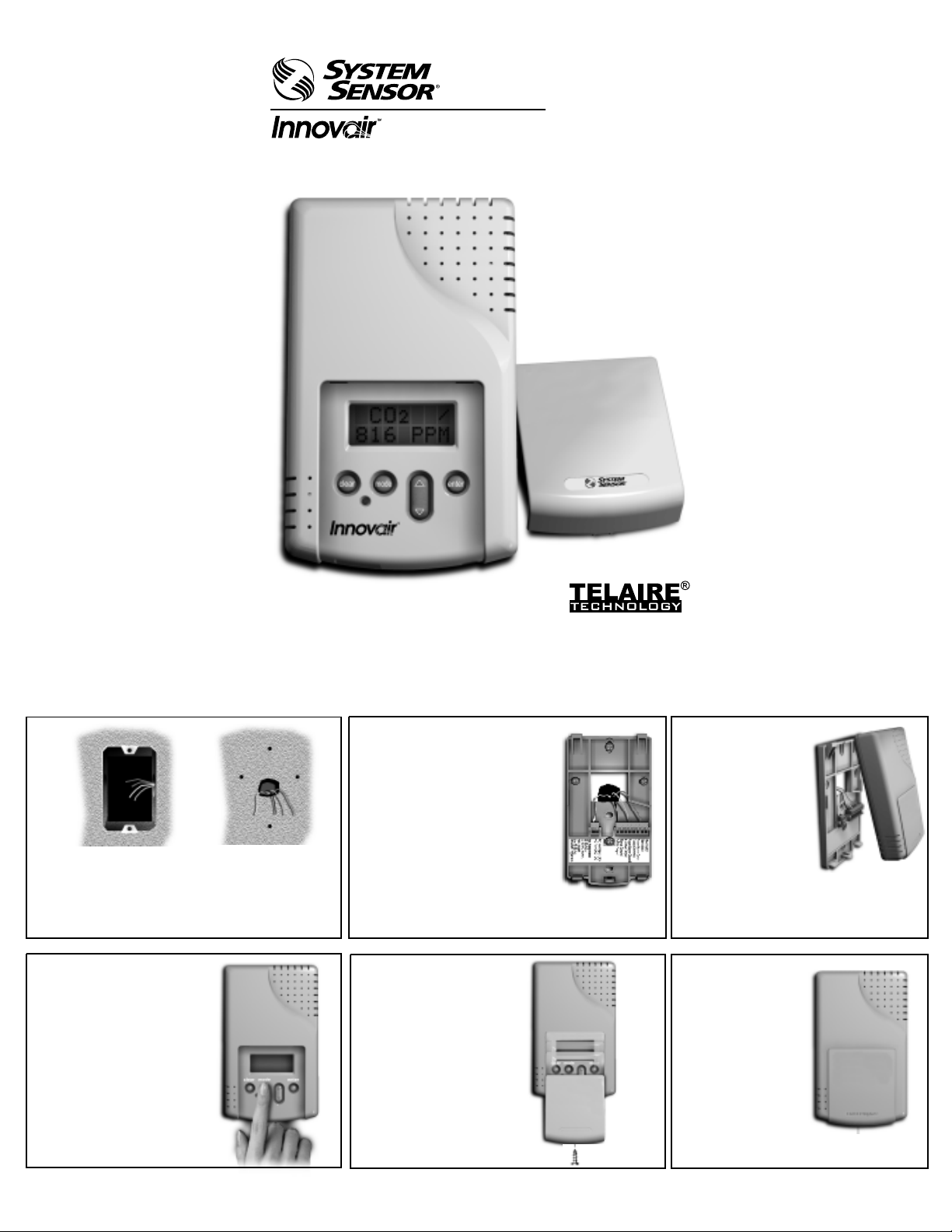
Installation
1 . 2 .
Use the mounting plate
Prepare for installation by
using the mounting holes
configured for US or
European junction boxes.
In less than 2 minutes, the
4 .
sensor will stabilize and display
the “Normal Mode” (current
CO2 readings).
At this point one of nine
preset programs or one
custom channel can be
selected for operation. Use
the charts below to select a
preset or to select/modify
sensor settings.
OR
as a template to mark
mounting and wiring
holes.
5 .
Secure the Mounting Plate to
the wall or junction box and
make necessary wire
connections.
Terminal Block Designations
1 Not Used
2 Not Used
3 Relay Norm Open
4 Relay Common
5 Relay Norm Closed
6 4-20mA Output
7 Signal Ground
8 0-10V Output
1 AC+ / DC+
2 AC- / GND
Finish installation by
sliding the cover over
the menu keys and
secure with the
supplied screw.
3 .
6 .
Mount the
Controller on the
base by aligning
the top clips and
then securing to
the bottom clips. A
“snap” sound will
indicate that the
sensor is secure.
The sensor will
now have power.
Ready for
operation!
Page 2
Software Operation
Your new Innovair™ CD100VC CO2 Ventilation Controller uses state-of-the-art
dual beam Absorption Infrared™ Technology. This patented technology
provides a stable, accurate and reliable sensor.
The sensor is also equipped with Engelhard Sensor Technologies’ patented
TEMA (Time Extended Measurement Algorithm) software. The TEMA software
will automatically sense and adjust for any sensor drift minimizing calibration
frequency to once every five years.
The Ventilation Controller is shipped with 9 preset settings (named Standard
Sets) and one setting for customizing (named Non-Standard). Two additional
settings are available; altitude adjustments and TEMA (on/off). These two are
accessible without entering the Standard or Non-Standard settings.
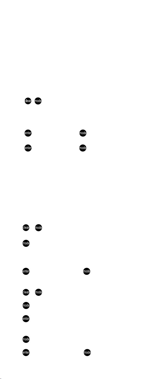
Altitude Correction and TEMA (On/Off)
1. Press + and hold (at least 5 seconds) until the sensor enters the
edit mode.
2. The first menu will be the Altitude correction. The adjustments will in-
crease/decrease in 500 ft. increments. To do this use the Up/Down Rocker
Button to adjust to the proper altitude.
3. Press to lock in value then press to proceed to TEMA.
4. Use the Up/Down Rocker Button to switch to On or Off.
5. Press to lock in value then press to proceed to Normal Mode.
Note: It is recommended that the TEMA feature is left on for the best
sensor operation.
Standard and Non-Standard Settings
The Non-Standard settings can be changed at any time after the sensor is
powered up. These settings have 7 variables and follow in sequence with the
Preset/Variable chart (see reverse side of this sheet). The Altitude and TEMA
feature can be changed without entering into the Non-Standard mode.
The Standard Settings (see reverse side of this sheet) are factory set and
cannot be changed. Like the Non-Standard settings, Altitude and TEMA can be
changed.
Select a Preset (from the STDSET Menu)
1. Press + and hold (at least 5 seconds) until the sensor enters the
edit mode.
2. Press 2 times. You will enter the “STDSET” Menu.
3. Use the Up/Down Rocker Button to select the Preset number.
“Preset” chart (on reverse side of this sheet) to select the desired
“Variables”
4. Press to lock in selection then press to return to monitoring mode.
.
Use the
For Custom Settings (from the NONSTD Menu)
1. Press + and hold (at least 5 seconds) until the sensor enters the
edit mode.
2. Press 2 times. You will enter the “STDSET” Menu.
3. Use the Up/Down Rocker Button to toggle to the “NONSTD” Menu and
press .
4. Use the Up/Down Rocker Button to scroll through the 8 variables. The
variables begin with customizing the ppm levels and end with hysterisis.
5. Press to move through variables. Use the Up/Down Rocker to toggle to
desired setting.
6. Press to lock in selection then press to continue to next Variable.
Page 3

Software Functionality
Specifications
Method
Dual Beam Absorption Infrared™
Patented TEMA self calibration
software
Sample Method
Diffusion or flow-through (50-100 ml/min)
Performance
Measurement Range
Analog output: 0-2000 ppm factory
default - Adjustable to 10,000 ppm
Digital display: 0-10,000 ppm
Sensitivity
±10 ppm
Resolution
±1 ppm
Operating Conditions
0°- 50°C (32°-122°F)
0 - 95% RH, non-condensing
Storage Temperatures
–40° - 70°C
Agency Certification
FCC Part 15 Class B
Calibration Interval
Five years / zero ppm gas offset adjust
Accuracy
Typical conditions 60-90°F (15-32°C):
0-2000 ppm: ±50 ppm or ±3% of
reading, whichever is greater
2,000-10,000 ppm: ±5% of reading
Extended conditions
32-122°F (0-50°C):
0-2000 ppm: ±100 ppm or ±5% of
reading, whichever is greater
2,000-10,000 ppm: ±7% of reading
Elevation (Pressure) Correction
Add 0.13% of reading per mm Hg
decrease from 760 (On-board
correction, user set)
Annual Drift
±10 ppm (negligible) with TEMA on
±20 ppm typical with TEMA off
Response Time 0..90% FS
<2 min.
Warm-Up Time @ 25°C
<2 minutes
Input/Output
Power
18-36 VAC RMS, 50/60 Hz
18-42 VDC polarity protected/dependent
70 mA average, 100 mA peak, at 24 VDC
Analog CO2 Output
0-10 VDC (100 Ohms output impedance)
4-20 mA (RLmax = 500 Ohms)
Both outputs available simultaneously
Relay
Normally Open or Normally Closed (wire
either way); gold bifurcated; 1 Amp at 24
VDC, resistive load, 2 Amp carrying
current. Adjustable setpoint, factory set
at 1000 ppm, 50 ppm hysteresis.
Wiring
18-28 AWG stranded copper wire only.
2 wires each for power, analog output,
relay.
Digital I/O
RS-232 interface
Note
CO2 readings may be temporarily
affected in the presence of certain portable two-way radios and cellular phones.
Specifications subject to change without
notice. Covered by United States
Patents: 5,060,508 and 5,163,332.
Other patents pending.
Warranty
System Sensor warrants its enclosed sensor to be free from defects in materials and workmanship under normal use and service for a period of 18 months from date of purchase by the
original owner. System Sensor makes no other express warranty for this sensor. No agent, representative, dealer, or employee of the Company has the authority to increase or alter the
obligations or limitations of this Warranty. The Companyís obligation of this Warranty shall be limited to the repair or replacement of any part of the sensor which is found to be defective in
materials or workmanship under normal use and service during the 18 month period commencing with the date of purchase by the original owner. After phoning System Sensorís toll free
number 800-SENSOR2 (736-7672) for a Return Authorization number, send defective units postage prepaid to: System Sensor, Warranty Service, RA#_______, 3825 Ohio Avenue, St.
Charles, IL 60174. Please include a note describing the malfunction and suspected cause of failure. The company shall not be obligated to repair or replace units which are found to be
defective because of damage, unreasonable use, modifications, or alterations occurring after the date of manufacture. In no case shall the Company be liable for any consequential or
incidental damages for breach of this or any other Warranty, expressed or implied whatsoever, even if the loss or damage is caused by the limitation of incidental or consequential
damages, so the above limitation or exclusion may not apply to you. This Warranty gives you specific legal rights, and you may also have other rights, and you may also have other rights
which may vary from state to state.
Featuring
System Sensor
3825 Ohio Avenue St. Charles, IL 60174
1-800-SENSOR2 (736-7672) Fax: 630-377-6495
Absorption Infrared™ is a trademark of Engelhard Sensor Technologies.
Telaire®is a registered trademark of Engelhard Sensor Technologies.
PN62511D - 31300
 Loading...