

Page 1
Installation Instructions for the Innovair™
CD100DH Duct Housing.
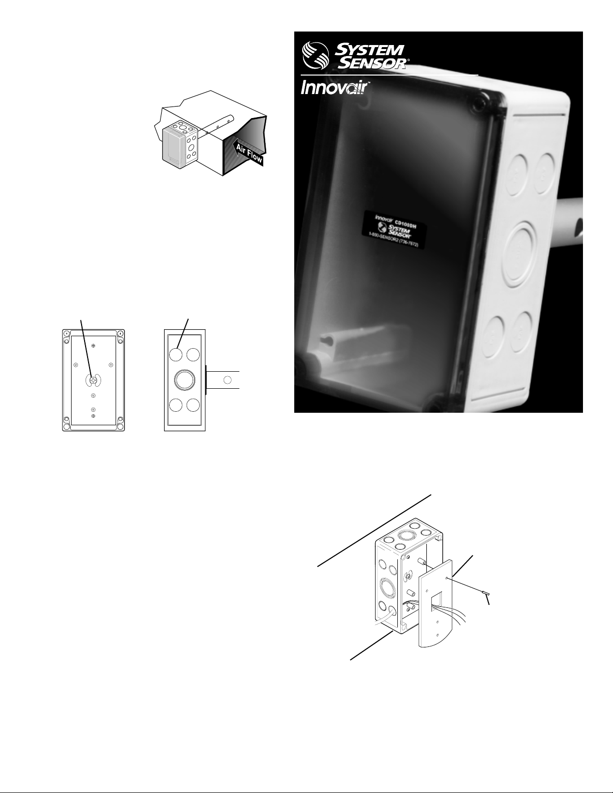
1. Overview
1.1 The mounting
location should be in
the return air duct.
Find a location that
will allow easy
access for modifying
or calibrating the
sensor .
2. Box Preparation
2.1 Remove the box cover by unscrewing the four
plastic screws.
2.2 For optimum sensing, the three holes located
on the inlet tube must face the duct air flow. If
the three inlet holes are facing the wrong
direction, simply turn the tube while making
sure the box is in the correct orientation.
CD100DH
Duct Housing for the CD100VC
Inlet Tube Screw
2.3 Secure the inlet tube to the housing by tightening the large screw located in the center of the
mounting bracket.
2.4 Using a sharp, pointed object, punch through a
conduit knockout. The duct housing is ready to
be mounted on the duct.
Conduit Knockout(s)
3. Installation
3.1 Using the template provided, mark the location
of the four mounting holes and one 1-1/4" hole
(for inlet tubing) on the duct.
3.4 Once the duct housing is secure, pass the
wiring through the open conduit hole and the
large opening on the sensor mounting bracket.
Sensor Base
Duct
3.2 On the duct, drill or punch the four mounting
holes and one 1-1/4" air inlet hole.
3.3 Mount the duct housing to the duct using four
sheet metal screws. V erify the three holes on
the inlet tube are facing into the airflow.
Mounting
Screws (4)
3.5 Using the four mounting screws (provided)
secure the sensor mounting bracket to the
four stand-off posts in the aspiration box.
Page 2
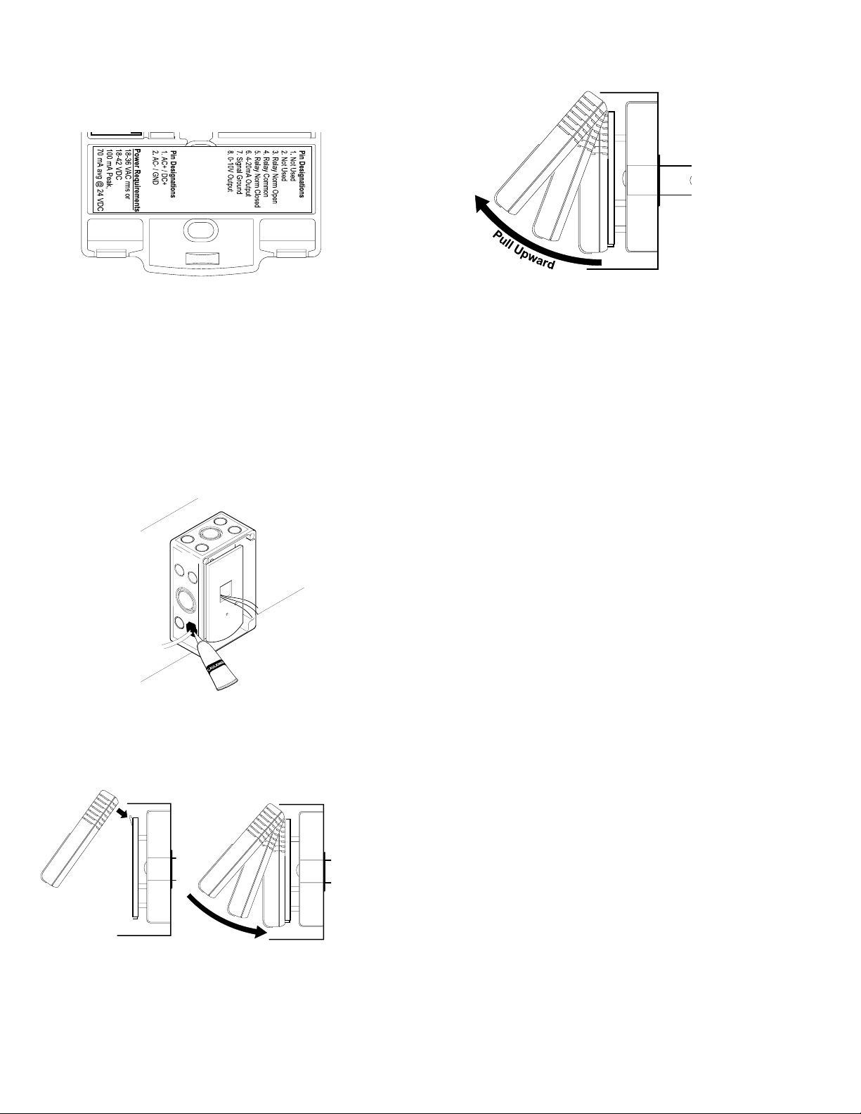
3.6 During wire installation, use caution while
routing the wires through the box. Strip the
wire insulation approximately 1/4" and ensure
the exposed wire is free of loose strands.
5. Sensor Removal
5.1 Remove the plastic cover.
3.7 Make the necessary wire connections by
following the pin designations on the terminal
block label. Insert the wires into the terminal
block and seat the wire insulation flush
against the terminal blocks. When wiring is
complete check for any wiring that may be
touching adjacent wires or terminal blocks.
3.8 For proper operation, it is important to maintain
an airtight seal within the duct housing. If any of
the “knockouts” were modified for wiring,
confirm that the opening is properly sealed with
caulk or putty.
4. Sensor Installation
4.1 The sensor can now be installed. First, mount
the top of the sensor to the top of the plastic
mounting plate and then firmly press the lower
half of the sensor into place.
5.2 The sensor is hinged at the top and fastened at
the lower end. To remove the sensor pull from
the bottom of the sensor and lift outward. The
sensor fits snugly into place, removal may
require a hard pull.
Warranty
System Sensor warrants its enclosed product to be free from defects in materials and
workmanship under normal use and service for a period of 18 months from date of
purchase by the original owner. System Sensor makes no other express warranty for this
sensor. No agent, representative, dealer, or employee of the Company has the authority
to increase or alter the obligations or limitations of this Warranty . The Company’s
obligation of this Warranty shall be limited to the repair or replacement of any part of the
product which is found to be defective in materials or workmanship under normal use and
service during the 18 month period commencing with the date of purchase by the original
owner. After phoning System Sensorís toll free number 800-SENSOR2 (736-7672) for a
Return Authorization number, send defective units postage prepaid to: System Sensor,
Warranty Service, RA#_______, 3825 Ohio Avenue, St. Charles, IL 60174. Please
include a note describing the malfunction and suspected cause of failure. The company
shall not be obligated to repair or replace units which are found to be defective because
of damage, unreasonable use, modifications, or alterations occurring after the date of
manufacture. In no case shall the Company be liable for any consequential or incidental
damages for breach of this or any other Warranty, expressed or implied whatsoever,
even if the loss or damage is caused by the limitation of incidental or consequential
damages, so the above limitation or exclusion may not apply to you. This Warranty
gives you specific legal rights, and you may also have other rights, and you may also
have other rights which may vary from state to state.
4.2 Upon power up, the LCD will read “INITIAL
WARMUP” for approximately 15 seconds and
after 1 minute the sensor will start reading
ambient CO2 levels.
4.3 Complete the installation by fastening the lid of
the box and tightening the four plastic screws.
System Sensor
3825 Ohio Avenue St. Charles, IL 60174
1-800-SENSOR2 (736-7672) Fax: 630-377-6495
Absorption Infrared™ is a trademark of Engelhard Sensor Technologies
Telaire® is a registered trademark of Engelhard Sensor Technologies
PN 62518B
10499
 Loading...