

Page 1
INSTALLATION INSTRUCTIONS
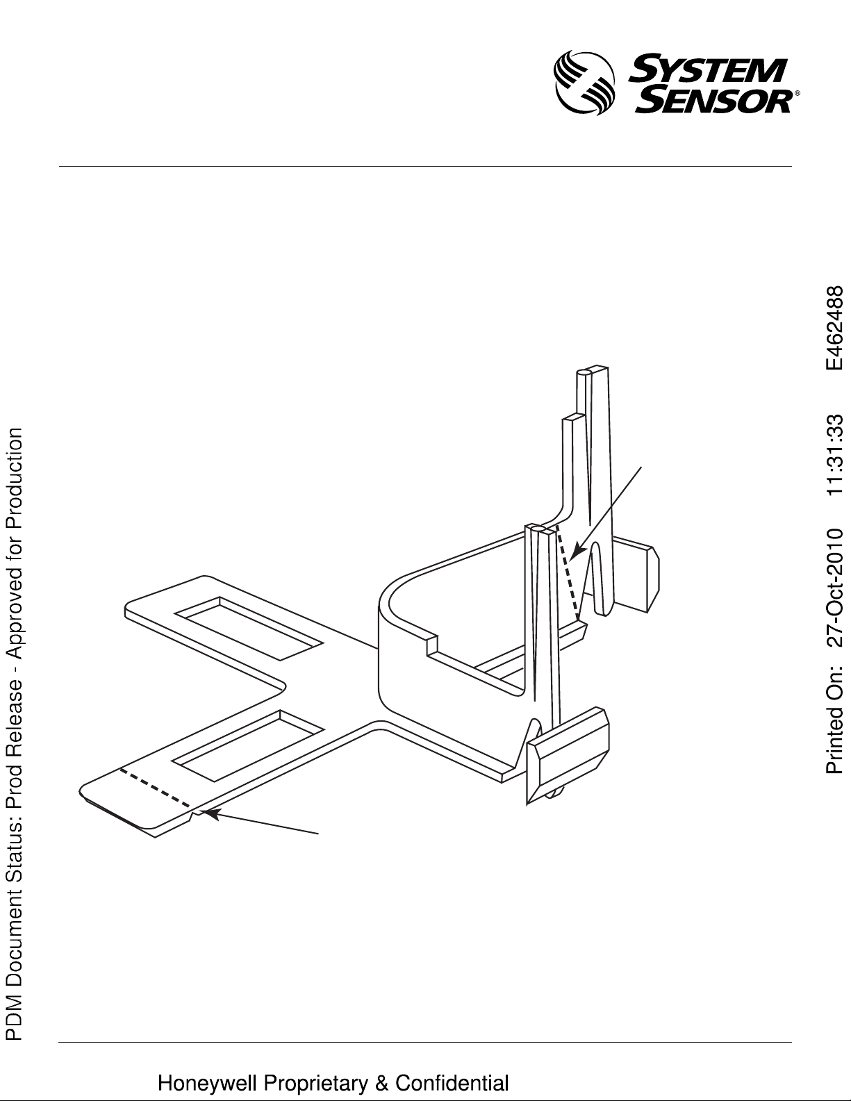
Cut here for
modules whose
Communication Lines
attach to
Terminals 0 and 1.
Cut here for
modules whose
Communication Lines
attach to
Terminals 1 and 2.
CB500 Wiring Barrier
I56-1483-00
3825 Ohio Avenue, St. Charles, Illinois 60174
1-800-SENSOR2, FAX: 630-377-6495
www.systemsensor.com
The CB500 barrier is used to separate power limited and nonpower limited wiring in a junction box. It is designed for multiple
applications, and one plastic tab must be removed prior to installation into a junction box.
Refer to the installation manual for the module being installed
to determine which screw terminals are used to attach the Communication Lines. Then, use diagonal cutters to cut off the appropriate tab on the barrier, as shown in the diagram below.
Prior to installing the barrier into the junction box, peel off the
label which says SIGNALING LOOP CIRCUIT TERMINALS ARE
POWER LIMITED. OTHERS ARE NOT. Affix this label over that
portion of the label on the back of the module which says ALL
CIRCUITS ARE POWER LIMITED.
Additional instructions on the installation of this barrier can be
found in the installation manual for the module.
C0686-00
D500-43-00 I56-1483-00
 Loading...