

Page 1
Pittway Tecnologica S.r.l., Via Caboto 19/3, 34147 Trieste, Italy
© System Sensor 2009 I56-2668-002
1
D550-33-00
B501AP / B524HTR
1
2
3
4
60 mm
SHIELD
102 mm
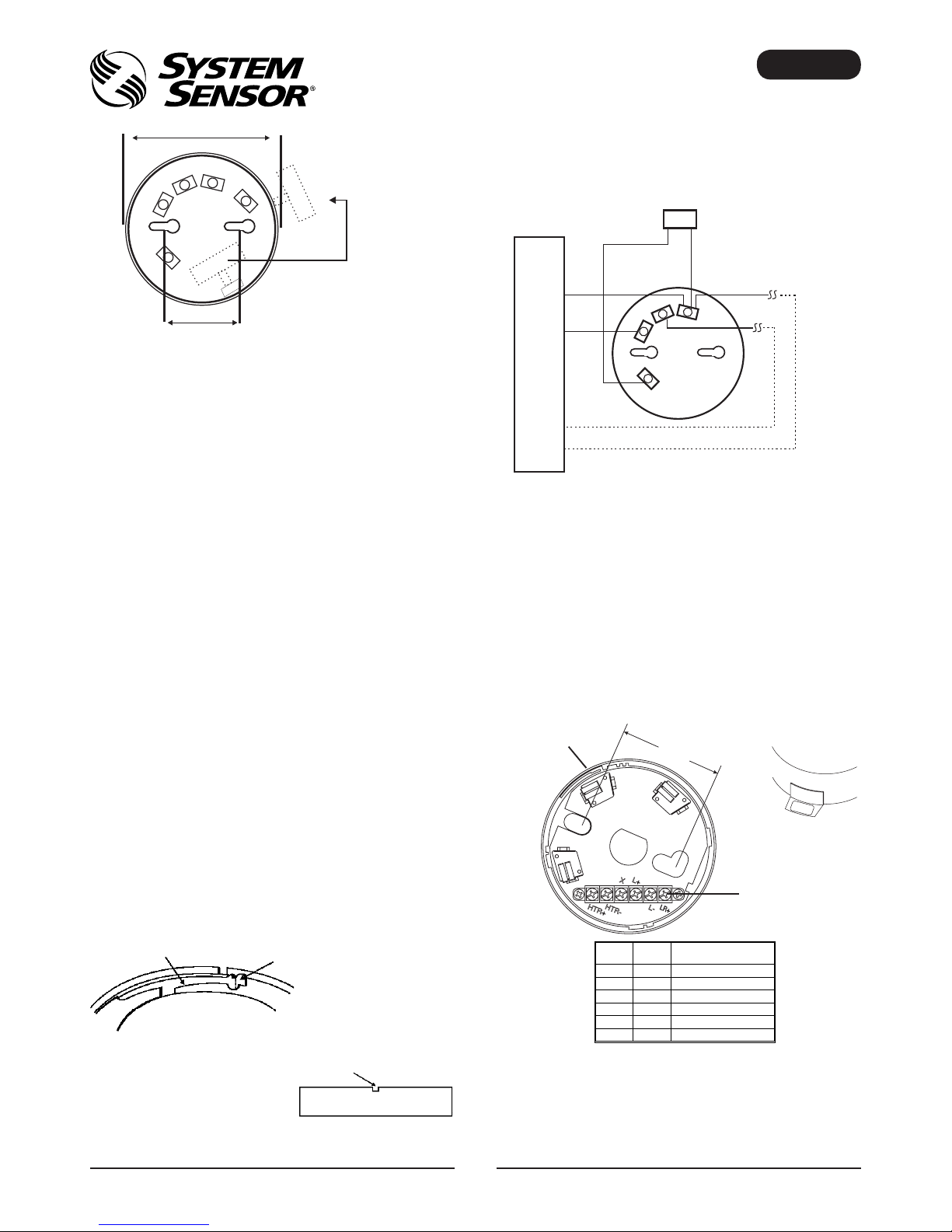
Notes:
1. The B524HTR requires an external power supply to drive the heater resistors
2. Ensure all terminals are fully screwed home prior to installation of the sensor
3. A self adhesive address tag is available for use with the B524HTR, which
is stuck to the side of the base, and labelled as appropriate to allow the
sensor address to be determined without removal of the sensor head
B501AP (-IV, -BK)
Address Tag
Height 22.5 mm
Weight 39 g
INSTALLATION INSTRUCTIONS FOR B501AP (-IV, -BK) AND
B524HTR INTELLIGENT SENSOR BASES
Before installing bases, please thoroughly read System Sensor’s Guide to
Intelligent Fire Systems, which gives information on sensor spacing, placement,
zones and applications. Copies are available from System Sensor at no charge.
GENERAL DESCRIPTION
These bases are designed for use with all System Sensor 500, 200, 200+ and
200 Advanced intelligent ranges of sensors and their variants (Note: If the
B524HTR is used with 200 Advanced Isolator sensors, the isolator feature will not
function. The standard B501AP is white, an IV suffix indicates the base is ivory in
colour, a BK suffix indicates the base is black. Please refer to the control panel
manufacturer for compatibility information.
INSTALLATION
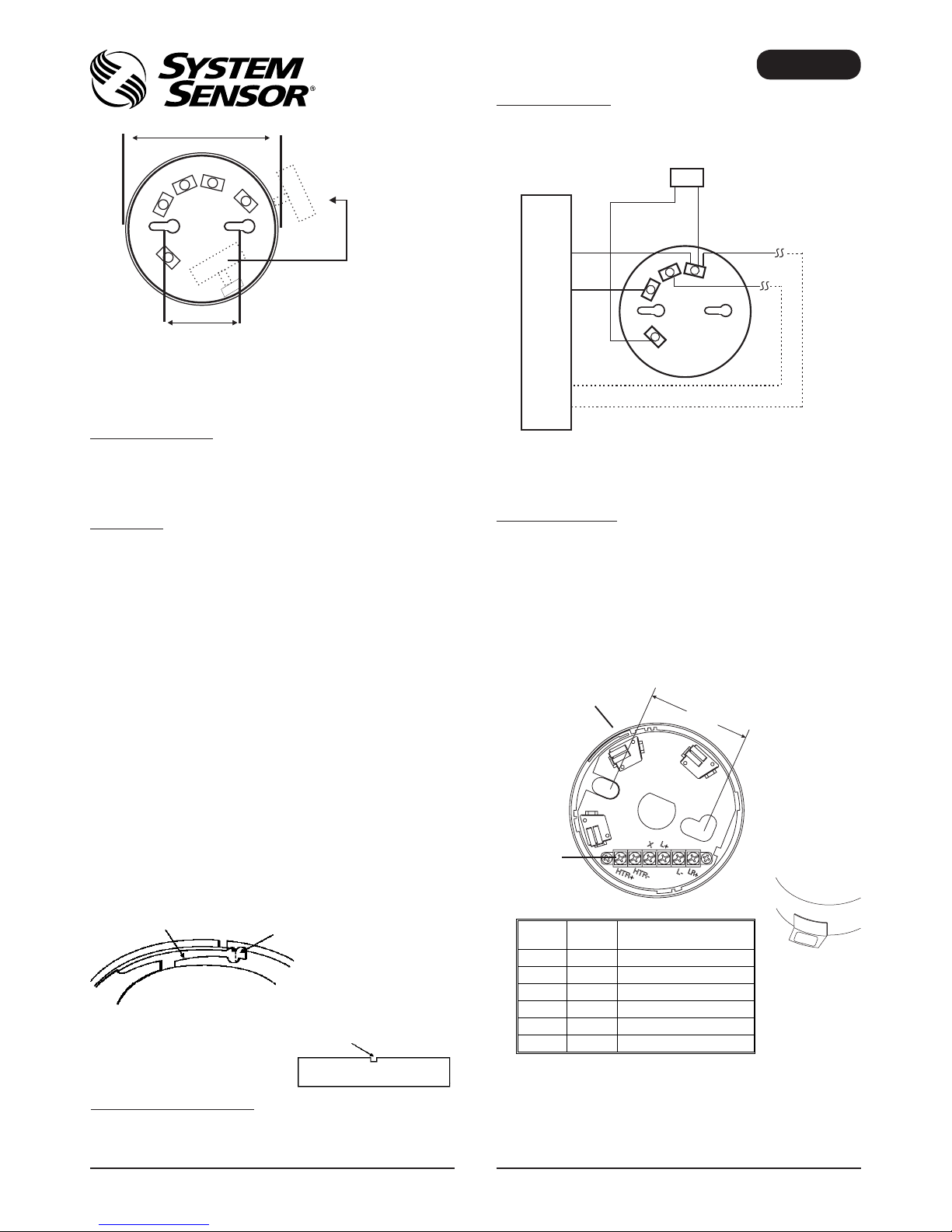
Mounting
The sensor base should be mounted using pan headed screws, with a maximum
diameter of 4mm, and with a maximum head diameter of 8mm. If required,
suitable junction boxes may be used. Standard mounting hole centres are 60mm,
however the B501AP offers from 50mm to 60mm and the B524HTR from 51mm
to 60mm.
The B501AP features knock-outs in the side of the base to allow the access
of surface mounted cabling. Match the markings on the knock-outs to ensure
perpendicular or opposed points (either blank or marked I or II).
Wiring
All wiring should be installed in compliance with local codes and standards, and
the authority having jurisdiction.
The base terminals are designed to accept cables with cross sectional areas
between 0.75mm² and 2.5mm². Reference should always be made to the control
panel specifications for acceptable cable parameters.
Note: To ensure supervision of contacts, the wire run must be broken. Do not loop
the wire under the terminals.
See diagrams opposite for wiring details.
Tamper Resist Feature
B500 bases also include a tamper resist feature, which when activated prevents
removal of the sensor head without the use of a tool.
To activate this feature, break off the tab on the base prior to installing the sensor
(figure 1a). To remove the sensor once this tamper resist is activated, place a
small bladed screwdriver into the slot on the side of the base, push the lever away
from the sensor and rotate the sensor anti clockwise (see figure 1b).
Note: Do not activate the feature if a head removal tool is to be used; this feature
is not reversible without damaging the base.
REMOTE ANNUNCIATOR OPTION
The RA100Z Remote Annunciator LED is available as an optional accessory. This
unit has a rectangular plate, which fits US single gang light switch boxes.
If a different remote annunciator is to be used, ensure that it is suitably rated for
operation with System Sensor intelligent sensors: 22.5V, 10.8mA at 24VDC supply.
Figure 1a: Activation of Tamper Resist Feature
Plastic Lever Break tab at dotted line by twisting
towards centre of base
Figure 1b: Removing Sensor Head From Base
Use a small bladed screwdriver to push
plastic in the direction of the arrow.
B501AP (-IV, -BK) BASE
If the sensor address needs to be visible without the removal of the sensor head,
break off the address tag from inside the base and place in the slot on the outside
of the base as required.
The tamper resist tab is located in the wall of the base between terminals 2 and 4.
Compatible Control Panel
Remote Indicator
22.5V Nominal
Terminal 1: Loop (-) In and Out and Remote Annunciator (-)
Terminal 4: Loop (+) Out
Terminal 2: Loop (+) In
Terminal 3: Remote Annunciator (+)
B524HTR HEATER BASE
This base contains an anti-condensation heater and is suitable for low temperature
applications.
B524HTR Specifications:
Diameter: 103 mm
Height: 36 mm
Weight: 92 g
Maximum Voltage: 32 V (dc or ac)
Power at 24V: 1.9 W
Maximum permissible peak power: 4W
Equivalent heating resistor value: 300 Ohms
Operating temperature: -30°C to +60°C
Operating humidity range: 10% to 93% Relative Humidity (Non-condensing)
60 mm
Address Tag
Z3 A55
Tamper Resist Tab
Terminal Strip
(See Table)
Terminal
PCB
Label
Connection
1
HTR+
HTR+: Heater Power Supply
2
HTR-
HTR-: Heater Power Supply
3 X Not Used (Shield)
4
L+
Loop +
5
L-
Loop -
6
LR+
Remote Annunciator +
ENGLISH
1
2
3
4
-
-
-
+
+
+
Page 2
Pittway Tecnologica S.r.l., Via Caboto 19/3, 34147 Trieste, Italy
© System Sensor 2009 I56-2668-002
2
D550-33-00
B501AP / B524HTR
1
2
3
4
60 mm
SHIELD
102 mm
Tag dell’indirizzo
Tag dell’indirizzo
B501AP (-IV, -BK)
Altezza 22,5 mm
Peso 39 g
ISTRUZIONI DI INSTALLAZIONE DI BASI DI SENSORI
INTELLIGENTI B501AP (-IV, -BK) E B524HTR
Prima dell’installazione delle basi, leggere attentamente la “Guida per rilevatori di
fumo intelligenti” che fornisce informazioni dettagliate su spazio, posizionamento,
disposizione e applicazioni del sensore. Copie di questa guida possono essere
richieste gratuitamente a System Sensor.
DESCRIZIONE GENERALE
Queste basi sono state progettate per l’uso con qualsiasi gamma di sensori
intelligenti 500, 200, 200+ e 200 Advanced System Sensor e loro varianti (Nota:
In caso di utilizzo del modello B524HTR con sensori dotati di isolamento 200
Advanced, la funzione di isolamento non funziona. Il modello B501AP standard
è bianco, il suffisso IV indica che la base è di color avorio mentre il suffisso
BK indica che la base è nera. Per informazioni sulla compatibilità rivolgersi al
produttore del pannello di controllo.
INSTALLAZIONE
Montaggio
Per il montaggio della base del sensore utilizzare viti a testa troncoconica con un
diametro di max. 4 mm e un diametro max. della testa di 8 mm. Se necessario è
possibile utilizzare apposite centraline. I fori standard di montaggio misurano 60
mm, tuttavia il modello B501AP dispone di fori da 50 – 60 mm mentre il modello
B524HTR da 51 – 60 mm.
Il modello B501AP presenta delle fessure sul lato della base che consente di
accedere al cablaggio per il montaggio a superficie. Far combaciare i segni sulle
fessure per punti perpendicolari o opposti (vuoti o contrassegnati da I o II).
Cablaggio
Il cablaggio deve essere installato conformemente ai codici e agli standard locali
e a quanto stabilito dall’autorità competente.
I terminali della base sono stati progettati per alloggiare cavi con sezioni trasversali
comprese tra 0,75 mm² e 2,5 mm². Per i parametri corretti dei cavi si consiglia di
fare sempre riferimento alle specifiche del pannello di controllo.
Nota: Per garantire la supervisione dei contatti, il filo utilizzato deve essere rotto.
Non avvolgere il filo sotto ai terminali.
Per i dettagli sul cablaggio ved. gli schemi in dotazione.
Funzione di antimanomissione
Le basi B500 sono dotate di una funzione di antimanomissione che, quando
attivata, impedisce la rimozione della testa del sensore senza l’uso di un utensile.
Per attivare questa funzione, rompere la linguetta presente sulla base prima
dell’installazione del sensore (figura 1a). Per rimuovere il sensore una volta
attivata questa funzione antimanomissione, inserire la lama piatta di un piccolo
cacciavite nello slot presente sul lato della base, spingere la leva dalla parte
opposta del sensore e ruotarlo in senso antiorario (ved. figura 1b).
Nota: Non attivare questa funzione qualora si debba utilizzare un utensile per la
rimozione della testa; questa funzione infatti non è reversibile a senza il rischio di
danneggiare la base.
Leva di plastica
Rompere la linguetta lungo la linea
tratteggiata ruotandola verso il
centro della base
Figura 1b: Rimozione della testa del sensore dalla base
Utilizzare un piccolo cacciavite a lama piatta per spingere la
plastica nella direzione della freccia
ANNUNCIATORE REMOTO OPZIONALE
Il LED Annunciatore remoto RA100Z è disponibile come accessorio opzionale.
Questo dispositivo presenta una placca rettangolare compatibile con un light
switch box ad accoppiamento singolo US.
In caso di utilizzo di un diverso annunciatore remoto, accertarsi che la sua
potenza sia idonea al funzionamento con sensori intelligenti System Sensor:
alimentazione 22,5 V, 10.8 mA a 24 V CC.
BASE B501AP (-IV, -BK)
Se l’indirizzo del sensore deve essere visibile senza ricorrere alla rimozione
della testa del sensore, rompere il tag dell’indirizzo dall’interno della base e
posizionarlo nello slot all’esterno della base secondo necessità.
La linguetta antimanomissione si trova sul lato della base tra i terminali 2 e 4.
Pannello di controllo compatibile
Terminale 1: Loop In e Out (-) e Annunciatore remoto (-)
Terminale 4: Loop Out (+)
Terminale 2: Loop In (+)
Terminale 3: Annunciatore remoto (+)
BASE DEL RISCALDATORE B524HTR
Questa base contiene un riscaldatore anticondensa ed è indicata per applicazioni
a basse temperature.
Specifiche di B524HTR:
Diametro: 103 mm
Altezza: 36 mm
Peso: 92 g
Tensione massima: 32 V (CC o CA)
Potenza a 24V: 1.9 W
Potenza di picco massima consentita: 4 W
Valore del resistore di riscaldamento equivalente: 300 Ohm
Temperatura d’esercizio: da -30°C a +60°C
Range dell’umidità operativa: dal 10% al 93% di umidità relativa (senza condensa)
60 mm
Note:
1. Il B524HTR necessita di un alimentatore esterno per il funzionamento dei
resistori di riscaldamento
2. Prima dell’installazione del sensore accertarsi che tutti i terminali siano ben
avvitati
3. Con il B524HTR può essere utilizzato un tag dell’indirizzo autoadesivo che si
fissa al lato della base ed è etichettato come appropriato al fine di consentire
la determinazione dell’indirizzo del sensore senza la rimozione della testa del
sensoreTag dell’indirizzo
Z3 A55
Figura 1a: Attivazione della funzione di antimanomissione
Indicatore remoto 22.5 V Nominale
Linguetta di
antimanomissione
Morsettiera
(ved. tabella)
Terminale
Etichetta
PCB
Connessione
1
HTR+
HTR+: alimentazione riscald.
2
HTR -
HTR - : alimentazione riscald.
3
X
Non utilizzata (Schermo)
4
L+
Loop +
5
L -
Loop -
6
LR+
Annunciatore remoto +
ITALIANO
1
2
3
4
-
-
-
+
+
+
Page 3

Pittway Tecnologica S.r.l., Via Caboto 19/3, 34147 Trieste, Italy
© System Sensor 2009 I56-2668-002
3
D550-33-00
B501AP / B524HTR
1
2
3
4
60 mm
SHIELD
102 mm
Notas:
1. La base B524HTR requiere una fuente de alimentación externa para poder
suministrar la corriente necesaria a la resistencia calefactora.
2. Asegúrese de que todos los terminales están bien atornillados antes de instalar
el detector.
3. La base B524HTR dispone de una etiqueta autoadhesiva que se puede pegar
en el lateral de la base. Así, se puede ver la dirección del detector sin necesidad
de extraerlo de la base.
Etiquetado de dirección
B501AP (-IV, -BK)
Altura: 22,5 mm
Peso: 39 g
INSTRUCCIONES DE INSTALACIÓN DE LAS BASES
B501AP (-IV, -BK) Y B524HTR PARA SENSORES INTELIGENTES
Antes de instalar las bases, lea atentamente la guía de System Sensor para
sistemas analógicos de protección contra incendios que contiene información
sobre la distancia, ubicación, tipo de zonas y aplicaciones de los detectores.
System Sensor puede proporcionarle copias gratuitas de este manual.
DESCRIPCIÓN GENERAL
Estas bases se utilizan con los sensores analógicos de System Sensor de la
serie 500, 200, 200+ y 200 Advanced y sus variantes (Nota: Si la base B524HTR
se utiliza con los sensores con aislador de la serie 200 Advanced, la función
de aislador no funcionará. La base estándar B501AP es blanca; el sufijo IV
(ivory) indica que es de color marfil y el sufijo BK (black) que es de color negra.
Consulte al fabricante de la central de incendios si desea información sobre la
compatibilidad de los equipos.
INSTALACIÓN
Montaje
La base se debe montar utilizando tornillos con un diámetro de rosca máximo
de 4mm y un diámetro de cabeza de 8mm como máximo. Si es necesario, se
pueden utilizar también cajas de conexiones. La distancia entre los centros de
los orificios de montaje es de 60mm, sin embargo la base B501AP le ofrece una
distancia entre orificios de entre 50mm y 60mm y la B524HTR una distancia entre
51mm y 60mm.
En la periferia de la base B501AP hay cuatro orificios pretaladrados para el
acceso lateral del cable en montaje de superficie. Realice los orificios de forma
que queden perpendiculares u opuestos.
Cableado
El cableado debe cumplir con las normativas, reglamentos locales y la autoridad
con jurisdicción.
Los terminales de la base aceptan cables entre 0,75mm2 y 2,5mm2. Consulte las
especificaciones de la central para informarse sobre la resistencia y capacidad
del cable adecuadas.
Nota: Para garantizar una supervisión correcta de los contactos, el recorrido del
cable debe cortarse. No haga ramales con el cable bajo los terminales
Véase los diagramas de conexionado.
Opción antisabotaje (bloqueo de extracción del detector)
Mediante esta opción se impide que se extraiga el detector si no es mediante el
uso de herramientas. Para ello, corte la pestaña de la base antes de instalar el
detector (fig. 1a). Para extraer el detector bloqueado, coloque un destornillador
pequeño en la ranura de la base, empuje la pestaña de plástico hacia el interior
de la base y gire el detector en sentido contrario a las agujas del reloj (fig. 1b).
Nota: No active esta opción si va a utilizar herramientas para extraer el detector,
ya que no es reversible.
Figura 1a: Activación de la opción antisabotaje
Pestaña de plástico
Rompa la pestaña por la línea de puntos
girándola hacia el centro de la base.
Figura 1b: Extracción del detector de la base
Utilice un destornillador pequeño para empujar la pestaña de
plástico en la dirección de la flecha.
B501AP (-IV, -BK) Base
Si la dirección del detector debe estar visible sin desmontarlo de la base, rompa
la pieza donde está anotada la dirección dentro de la base y colóquela en la
ranura, por la parte externa de la base. La pestaña antisabotaje se encuentra
entre los terminales 2 y 4 de la base.
Central de incendios compatible
Terminal 1: Entrada y salida de Lazo (-) y Anunciador Remoto (-)
Terminal 4: Salida de Lazo (+)
Terminal 2: Entrada de Lazo (+)
Terminal 3: Anunciador Remoto (+)
BASE CON CALEFACTOR B524HTR
Esta base dispone de un calefactor anticondensación y es adecuada para instalar
en ambientes con bajas temperaturas.
Especificaciones B524HTR:
Diámetro: 103 mm
Altura: 36 mm
Peso: 92 g
Tensión máxima: 32 V (cc o ca)
Alimentación a 24V: 1,9 W
Pico máx, de alimentación permitido: 4W
Valor de resistencia equivalente: 300 Ohms
Temperatura de funcionamiento: de -30°C a +60°C
Humedad de funcionamiento: de 10% a 93% HR (sin condensación)
60 mm
Pieza donde se pega la
etiqueta con la dirección
del detector
Z3 A55
OPCIÓN DE SEÑALIZACIÓN REMOTA
El modelo de LED Anunciador Remoto RA100Z está disponible como accesorio
opcional. Esta unidad consta de una placa rectangular que se instala en cajas
eléctricas estándar. Si se utiliza un modelo de anunciador diferente, asegúrese
de que es compatible con los detectores de System Sensor, es decir, 22,5V;
10,8mA a 24Vcc.
Indicador remoto 22,5V Nominal
Terminales
(ver tabla)
Pestaña antisabotaje
Anunciador Remoto +LR+6
Lazo -L-5
Lazo +L+4
Sin uso (pantalla)X3
HTR -: Alimentación calefactorHTR-2
HTR +: Alimentación calefactorHTR+1
ConexiónMarca
en la
placa
Terminal
Anunciador Remoto +LR+6
Lazo -L-5
Lazo +L+4
Sin uso (pantalla)X3
HTR -: Alimentación calefactorHTR-2
HTR +: Alimentación calefactorHTR+1
ConexiónMarca
en la
placa
Terminal
ESPAÑOL
1
2
3
4
-
-
-
+
+
+
Page 4

Pittway Tecnologica S.r.l., Via Caboto 19/3, 34147 Trieste, Italy
© System Sensor 2009 I56-2668-002
4
D550-33-00
B501AP / B524HTR
1
2
3
4
60 mm
SHIELD
102 mm
Adressierung
Adressierung
B501AP (-IV, -BK)
Höhe 22.5 mm
Gewicht 39 g
INSTALLATIONSANLEITUNG FÜR B501AP (-IV, -BK) UND
B524HTR INTELLIGENTE MELDERSOCKEL
Vor der Installation von Meldersockeln lesen Sie bitte gründlich die „Richtlinien
für intelligente Feuermeldesystem“ von System Sensor durch. Darin sind
Informationen über Abstände, Anordnungen, Zonen und Anwendungen von
Meldern enthalten. Kostenlose Exemplare sind bei System Sensor erhältlich.
ALLGEMEIN
Die Meldersockel sind für den Betrieb mit den Brandmeldern der Serie 500,
200, 200+ und den Meldern Typ 200 mit erhöhter Intelligenz sowie deren
Modellvarianten geeignet (Hinweis: Bei dem Einsatz des Meldersockels B524HTR
in Verbindung mit den intelligenten Brandmeldertypen 200 mit Isolator wird die
Isolatorfunktion nicht unterstützt. Der Standard Meldersockel B501AP hat die
Farbe weiß. Die Typenbezeichnung „IV“ steht für die Gehäusefarbe Elfenbein und
„BK“ für Schwarz. Weitere Informationen zur Kompatibilität entnehmen Sie bitte
der Dokumentation der Brandmelderzentrale.
INSTALLATION
Montage
Der Meldersockel sollte mit Flachkopfschrauben (max. 4mm Gewindedurchmesser
und max. 8mm Kopfdurchmesser) montiert werden. Falls notwendig sollten
passende Anschlussdosen verwendet werden. Der Standardabstand der
Befestigungspunkte beträgt 60mm, mit dem Sockel B501AP sind jedoch 50mm
bis 60mm und mit Sockel B524HTR sind 51mm bis 60mm möglich.
Der Sockel B501AP hat seitliche Sollbruchstellen für die Kabeleinführung bei
der Aufputz-Montage. Die Markierung der Sollbruchstellen (keine oder mit I
bzw. II markiert) müssen für eine geradlinige oder gegenläufige Kabelführung
ausgerichtet werden.
VERDRAHTUNG
Die Verdrahtung muss den lokalen und nationalen Normen und Anforderungen
entsprechen. An die Anschlussklemmen des Meldersockels können Kabel mit
einem Querschnitt von 0,75mm² bis 2,5mm² angeschlossen werden. Beachten
Sie hierzu die Hinweise zur Spezifikation der Anschlusskabel in der Anleitung der
Brandmelderzentrale.
Hinweis: Zur Überwachung der Kontakte muss die Kabelführung unterbrochen
werden. Kabel nicht unter den Klemmen durchschleifen.
Siehe nebenstehende Grafik zur detaillierten Verdrahtung.
SABOTAGESCHUTZ / ENTNAHMESICHERUNG
Die B500 Meldersockel verfügen über eine Melderentnahmesicherung durch die
- im aktivierten Zustand – eine Entnahme des Melders aus dem Sockel ohne
Werkzeug nicht möglich ist
Zur Aktivierung dieser Sicherung ist die Kunststoffzunge vor der Installation aus dem
Meldersockel zu entfernen (Abbildung 1a). Um die Melder trotz eingebauter Sicherung
aus dem Sockel zu entnehmen, kann ein schmaler Schraubendreher in die seitliche
Öffnung des Sockels eingesteckt, der Kunststoffhebel nach innen gedrückt und der
Melder durch eine Linksdrehung entnommen werden (Abbildung 1b).
Hinweis: Bei aktivierter Entnahmesicherung ist der Einsatz des Melderentnahmewerkzeuges nicht möglich ohne den Sockel zu beschädigen.
Abbildung 1a: Melderentnahmesicherung aktivieren
KUNSTSTOFFHEBEL
KUNSTSTOFFZUNGE AN DER
GEPUNKTETEN LINIE DURCH EINE
DREHUNG ZUR INNENSEITE DES
SOCKELS ABTRENNEN.
Abbildung 1b: Melderkopf vom Sockel abnehmen
Falls eine andere Parallelanzeige eingesetzt werden soll ist sicherzustellen, dass
diese für den Betrieb in Verbindung mit den System Sensor Analogbrandmeldern
geeignet ist: 22,5V; 10,8mA @ 24VDC Versorgungsspannung.
B501AP (-IV, -BK) MELDERSOCKEL
Wenn die Erkennung der Melderadresse gefordert ist, ohne dass der Melderkopf
aus dem Sockel entnommen werden muss, kann das Beschriftungsfeld aus der
Innenseite herausgetrennt und in die entsprechende Öffnung der Außenseite des
Meldersockels gesteckt werden.
Die Melderentnahmesicherung befindet sich an der Seite des Meldersockels
zwischen Klemme 2 und 4.
Kompatible Brandmelderzentrale
Klemme 1: Loop (-) IN und OUT und Parallelanzeige (-)
Klemme 4: Loop (+) Out
Klemme 2: Loop (+) In
Klemme 3: Parallelanzeige (+)
B524HTR BEHEIZBARER MELDERSOCKEL
Dieser Meldersockel enthält eine Antikondensationsheizung für Anwendungen
bei niedrigen Temperaturen.
B524HTR Technische Daten:
Durchmesser: 103 mm
Höhe: 36 mm
Gewicht: 92 g
Maximale Spannung: 32 V (DC oder AC)
Leistung bei 24V: 1,9 W
Max. Spitzenleistung: 4W
Heizwiderstand: 300 Ohm
Betriebstemperatur: -30 °C bis +60 °C
Umgebungsbedingungen: 10% bis 93% relative Feuchte, ohne Betauung
60 mm
Hinweis:
1. Für den Meldersockel B524HTR ist eine externe Spannungsversorgung des
Heizwiderstandes erforderlich.
2. Stellen Sie sicher dass vor der Inbetriebnahme alle Anschlussklemmen fest
angezogen sind.
3. Für den Meldersockel B524HTR steht ein selbstklebendes Beschriftungsfeld
zur Verfügung, welches einfach an dem Meldersockel befestigt wird und die
Kennzeichnung des Melders ermöglicht ohne den Melderkopf aus dem Sockel
zu entfernen.
Z3 A55
MELDERPARALLELANZEIGEN
Optional steht die LED-Melderparallelanzeige RA100Z zur Verfügung. Durch
die rechteckige Montageplatte kann die Anzeige auf einer Schalterdose/
Unterputzdose befestigt werden.
Melderparallelanzeige
22.5V Nominal
Melderentnahmesicherung
(Öffnung)
Anschlussklemmen
(siehe Tabelle)
NUTZEN SIE EINEN SCHRAUBENDREHER MIT
SCHMALER KLINGE UM DEN KUNSTSTOFF IN
PFEILRICHTUNG HERAUSZUDRÜCKEN.
Klemme Platinenaufdruck Anschluss
1 HTR+ HTR+: Heizung Spannungsversorgung
2 HTR- HTR-: Heizung Spannungsversorgung
3 X Nicht belegt (Kabelabschirmung)
4 L+ Loop +
5 L- Loop 6 LR+ Parallelanzeige +
DEUTSCH
1
2
3
4
-
-
-
+
+
+
 Loading...