

Page 1
INSTALLATION AND MAINTENANCE INSTRUCTIONS
I56-2816-003R
B401BH-2
Sounder Bases
SpECIfICATIONS
Base Diameter: 6 inches (152 mm)
Base Height (less base and sensor): 0.75 inches (19mm)
Weight: 0.32 lb. (145 g)
Operating Temperature Range: 14° to 140°F (–10° to +60°C)
Operating Humidity Range: 10% to 95%, non-condensing
Electrical Ratings
Voltage: 17 to 32 VDC
Standby Current: 1.0 mA maximum
Alarm Current: 15 mA maximum
Maximum Ripple Voltage: 10% of supply voltage
Start-up Capacitance: 200 µF
Horn Input Current Requirement: 600 µA maximum
Sound Output: Greater than 90 dBa measured in anechoic room at 10 feet (3 meters),
24 volts. 85 dBa minimum measured in UL reverberant room.
Sounder Delay Time: 0.75 to 5.7 sec
BEfORE INSTALLINg
Please thoroughly read the, System Smoke Detector Application Guide, which
provides detailed information on detector spacing, placement, zoning, wiring,
and special applications. Copies of this manual are available from System Sensor. NFPA 72 and NEMA guidelines should be observed.
NOTICE: This manual should be left with the owner/user of this equipment.
IMPORTANT: The detector used with these bases must be tested and maintained regularly following NFPA 72 requirements. The detector used with
these bases should be cleaned at least once a year.
gENERAL DESCRIpTION
Model B401BH-2 sounder bases is intended for use with System Sensor 400
Series plug-in sensor heads in conventional 2-wire plug-in systems. Refer to
systems manuals for the maximum allowable number of units per loop. The
B401BH-2 requires an external 24VDC (nominal) supply with reverse polarity
capability. The connections of the external supply (terminals 1 and 2) and the
initiating loop (terminals 3, 4, and 5) are isolated in the B401BH-2 to prevent
electrical interaction between them.
A loop of horns can be made to sound by reversing the polarity of the external
supply.
NOTE: When the associated system is NOT used as a supplementary evacuation system, the external 24VDC supply must be treated as a component of the
main power supply system with the result that it falls under the requirements
of NFPA 72.
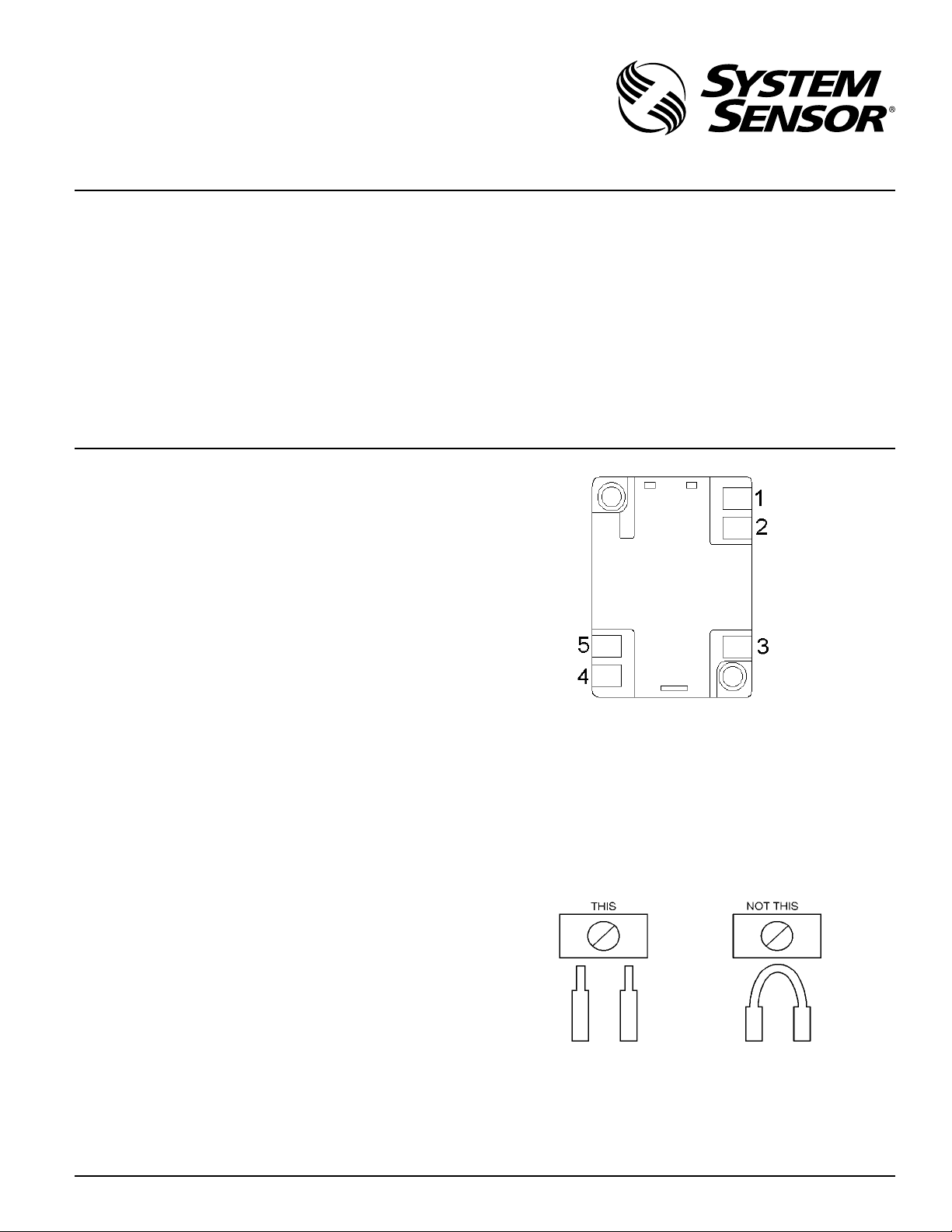
B401BH-2 TERMINALS
No. Function
1 External Supply Positive (+)
2 External Supply Negative (–)
3 Negative (–) V
4 Positive (+) V In
5 Positive (+) V Out
Terminals 3, 4, and 5 are used for the communication/initiating circuit.
INSTALLATION WIRINg gUIDELINES
All wiring must be installed in compliance with the National Electrical Code
and all applicable local codes and any special requirements of the authority
having jurisdiction, using the proper wire size. The conductors used to connect smoke detectors to control panels and accessory devices should be colorcoded to reduce the likelihood of wiring errors. Improper connections can
prevent a system from responding properly in the event of a fire.
fIgURE 1. TERMINAL LAyOUT :
For signal wiring (the wiring between interconnected detectors), it is recommended that the wire be no smaller than AWG 18. However, the screws and
clamping plate in the base can accommodate wire sizes up to AWG 12. The
use of twisted pair wiring or shielded cable for the power (+ and –) loop is
recommended to minimize the effects of electrical interference on the initiating loop.
Begin electrical connections by stripping about 3/8” insulation from the end
of the wire. Then, slide the bare end of the wire under the clamping plate and
tighten the clamping plate screw. Break the wire at each terminal to ensure
that the connections are supervised, as shown in Figure 2.
fIgURE 2.
DO NOT loop the wire under the clamping plate.
Check the zone wiring of the detector base before the detector heads are
installed. Perform continuity, base polarity, and dielectric tests on the wiring.
Smoke detectors and alarm system control panels have specifications for allowable supervision current. Consult the control panel manufacturer’s specifications for the total loop current supervision allowed for the control panel
being used before wiring the detector loops.
3825 Ohio Avenue, St. Charles, Illinois 60174
1-800-SENSOR2, FAX: 630-377-6495
www.systemsensor.com
C0471-00
C0473-00
D450-00-00 1 I56-2816-003R
Page 2
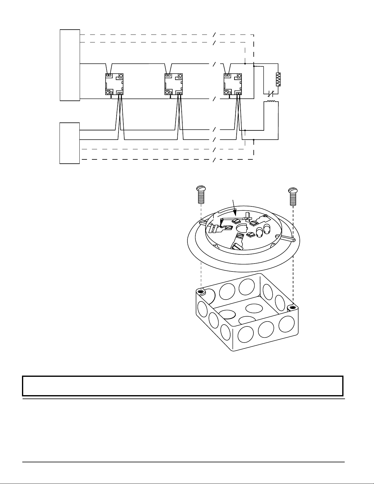
fIgURE 3. TypICAL WIRINg LAyOUT :
SCREWS
(NOT SUPPLIED)
DETECTOR
BASE
BOX
(NOT SUPPLIED)
SHORTING
SPRING
CLASS A OPTIONAL WIRING
(+) INIT.
4
5
3
UL LISTED COMPATIBLE
CONVENTIONAL CONTROL PANEL
SUPPLY
EXTERNAL 24V
(−) INIT.
(−)POWER
(+)POWER
4
5
3
1
2
CLASS A OPTIONAL WIRING
WIRINg INSTRUCTIONS
The shorting spring in the base will disengage automatically when the detector head is removed from the base.
DO NOT remove the shorting spring since it reengages as the detector head is
turned into the base, completing the circuit.
A typical wiring for a two-wire conventional system is shown in Figure 3. Refer to this diagram as needed while wiring the base into the system.
NOTE: Figure 3 shows external 24V supply polarity when
the loop system is in standby (NOT alarming).
MOUNTINg
NOTE: It is recommended that the base be completely wired before mounting.
See Figure 4. Attach the base directly to an electrical box using the screws
supplied with the box. Then, use the plastic screw covers, supplied with the
base, to cover the screws.
The sounder base is 1.1 inches (28 mm) deep. Electrical boxes must be 4 inches
(102 mm) square by at least 1-1/2 inches (38 mm) deep; 2-1/8 inches (54 mm)
is recommended.
TESTINg
Before testing, notify the proper authorities that the smoke detector system is undergoing maintenance and that the system will be temporarily out of service. Disable the zone or system undergoing maintenance to prevent unwanted alarms.
Detectors and bases must be tested after installation and following periodic
maintenance.
Test the B401BH-2 as follows:
1. Test the conventional detector head following the procedure in its manual. The B401BH-2 should sound approximately 0.75 to 5.7 seconds after
the detector alarms.
2. Reverse the polarity of the external 24 VDC supply. This should cause
every base in the loop to sound after approximately 0.75 to 5.7 seconds.
Please refer to insert for the Limitations of Fire Alarm Systems
4
5
1
2
3
1
2
UL
LISTED
EOL
RELAY
24V
fIgURE 4. MOUNTINg TO AN ELECTRICAL BOx:
UL
LISTED EOL
RESISTOR
C0956-01
C0503-01
THREE-yEAR LIMITED WARRANTy
System Sensor warrants its enclosed product to be free from defects in materials and
workmanship under normal use and service for a period of three years from date of
manufacture. System Sensor makes no other express warranty for this air duct smoke
detector. No agent, representative, dealer, or employee of the Company has the authority
to increase or alter the obligations or limitations of this Warranty. The Company’s obligation of this Warranty shall be limited to the replacement of any part of the product which
is found to be defective in materials or workmanship under normal use and service
during the three year period commencing with the date of manufacture. After phoning
System Sensor’s toll free number 800-SENSOR2 (736-7672) for a Return Authorization
number, send defective units postage prepaid to: System Sensor, Returns Department, RA
#__________, 3825 Ohio Avenue, St. Charles, IL 60174. Please include a note describing
the malfunction and suspected cause of failure. The Company shall not be obligated to
replace units which are found to be defective because of damage, unreasonable use,
modifications, or alterations occurring after the date of manufacture. In no case shall the
Company be liable for any consequential or incidental damages for breach of this or any
other Warranty, expressed or implied whatsoever, even if the loss or damage is caused by
the Company’s negligence or fault. Some states do not allow the exclusion or limitation of
incidental or consequential damages, so the above limitation or exclusion may not apply
to you. This Warranty gives you specific legal rights, and you may also have other rights
which vary from state to state.
D450-00-00 2 I56-2816-003R
©2010 System Sensor
 Loading...