

Page 1

INSTALLATION AND MAINTENANCE INSTRUCTIONS
2951 Intelligent Photoelectronic
3825 Ohio Avenue, St. Charles, Illinois 60174
Smoke Sensor
Specifications
Operating Voltage Range: 15 to 30 VDC
Current: 270µA Max. Communication active but not to device in blink mode
LED Current: 6.5 mA Continous ON
Operating Humidity Range: 10% to 93% Relative Humidity, noncondensing
Operating Temperature Range: 0° to 49°C (32° to 120°F)
Height: 1.95 inches (50 mm) installed in Base
Diameter: 4.0 inches (102 mm) installed in Base
Weight: 2.96 oz. (92 g)
Before Installing
This sensor must be installed in compliance with the control panel system installation manual. The installation must
meet the requirements of the A uthority Having Jurisdiction
(AHJ). Sensors offer maximum performance when installed
in compliance with the National Fire Protection Association
(NFPA); see NFPA 72, and all applicable codes, ordinances
and regulations.
General Description
Model 2951 is a plug-in type smoke sensor that combines a
photoelectronic sensing chamber with addressable-analog
communications. The sensor transmits an analog representation of smoke density over a communication line to a
control panel. The sensor’s address is set b y the Hand Held
Programmer (HHP ). An LED on the sensor is controlled b y
the panel to indicate sensor status.
The Model 2951 requires compatible addressable communications to function properly. Connect this sensor to
listed-compatible control panels only.
Spacing
System Sensor recommends spacing sensors in compliance
with NFPA 72. In low air flow applications with smooth
ceilings, space sensors 30 feet apart. For specific information regarding sensor spacing, placement, and special applications, refer to NFPA 72 or the S y stem Sensor Guide For
Proper Use of System Smoke Detectors, available at no
charge from System Sensor (P/N I56-407-XX).
Wiring Instructions
All wiring must be installed in compliance with the National Electrical Code, applicable local codes, and any special requirements of the Authority Having Jurisdiction.
Proper wire gauges should be used. The installation wires
should be color-coded to limit wiring mistakes and ease
system troubleshooting. Improper connections will prevent
a system from responding properly in the event of a fire.
NOTE: The mounting base (B901) uses SEMS Plate termi-
nals and can accommodate 2 wires each. The 2
wires can differ by a maximum of 2 wire gauges.
Remove power from the communication line before installing sensors.
All wiring must conform to applicable local codes, ordinances, and regulations.
1. Wire the sensor base (supplied separately) per the wiring diagram, see Figure 1.
2. Prior to installation, address the sensor using the Hand
Held Programmer (HHP ). See Hand Held Programmer
instruction manual for proper operation.
3. Install the sensor into the sensor base. Push the sensor
into the base while turning it clockwise to secure it in
place.
1-800-SENSOR2, FAX: 630-377-6495
A Division of Pittway
D200-86-00 1 I56-1321-00
Page 2
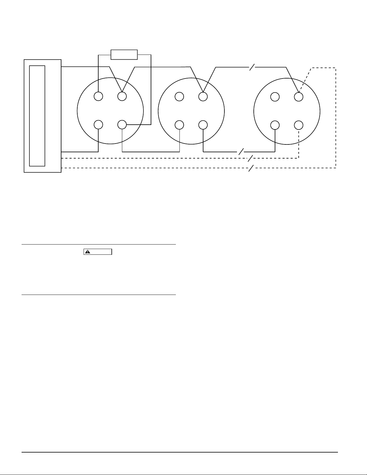
Figure 1:
Remote Annunciator
+
-
+
OUT
+IN/OUT
-
IN
-
+R/A
-
-
-
U.L. listed compatible control panel
4. After all sensors have been installed, apply power to the
control unit and activate the communication line.
5. Test the sensor(s) as described in the TESTING section
of this manual.
Dust covers provide limited protection against airborne
dust particles during shipping. Dust covers must be removed before the sensors can sense smoke. Remove sensors prior to heavy remodeling or construction.
+
CAUTION
CLASS A OPTIONAL WIRING
+R/A
+IN/OUT
-
OUT
IN
The sensor can be tested in the following ways:
A. Smoke Entry: Aerosol Generator
Aerosol generators for smoke entry testing are available
from a number of third party manufacturers (e.g.,
Gemini Scientific). Follo wing the manufacturer’ s instructions, apply aerosol until the panel alarms.
Coded signals, transmitted from the panel, can cause the
LEDs to blink, latch on, or latch off. Refer to the control
panel technical documentation for sensor LED status
operation and expected delay to alarm.
+R/A
-
OUT
+IN/OUT
-
IN
A78-2665-01
B. Sensitivity:
Testing
Before testing, notify the proper authorities that the system
is undergoing maintenance, and will temporarily be out of
service. Disable the system to prevent unwanted alarms.
All sensors must be tested after installation and periodically thereafter. Testing methods must satisfy the Authority
Having Jurisdiction (AHJ). Sensors offer maximum performance when tested and maintained in compliance with
NFPA 72 and all applicable codes, ordinances and regulations.
D200-86-00 2 I56-1321-00
The sensitivity of the detector can be monitored and
tested by the Hand Held Programmer. R efer to HHP documentation for sensitivity testing information. Certain
control panels may also monitor and test the detector’s
sensitivity. Refer to control panel documentation for sensitivity testing information. The sensitivity indication is
independent of communication. An acceptable sensitivity range is stamped on the back of the sensor.
A sensor that fails any of these tests should be cleaned as
described under CLEANING, and retested. If the sensor fails
after cleaning, it must be replaced and returned for repair.
When testing is complete, restore the system to normal operation and notify the proper authorities that the system is
back in operation.
Page 3

Figure 2:
SENSOR COVER
SCREEN
Cleaning
It is recommended that the detector be removed from its
mounting base to facilitate cleaning. The detector is
cleaned as follows:
NOTE: Before removing the detector, notify the proper authorities that the smoke detector system is undergoing
maintenance and will be temporarily out of service. Disable
the zone or system undergoing maintenance to pr event unwanted alarms.
SENSING CHAMBER
SENSOR
SENSOR BASE
A78-2666-00
1. Remove the sensor cover, see Figure 2. Grasp the cover
and the base, rotate the co v er counter clockwise and remove from the sensor base assembly.
2. Vacuum the screen carefully without removing it. If further cleaning is required continue with Step 3, other
wise skip to Step 6.
3. Remove the screen assembly by pulling it straight out
(see Figure 2).
4. Clean the sensing chamber and the inside of the screen
assembly. Use a vacuum or clean, compressed air to remove dust and debris.
5. Replace the screen assembly.
6. Replace the cover by locating it into the sensor base assembly and turning the cover clockwise until it locks
into place.
7. Reinstall the sensor.
8. When all sensors have been cleaned and reinstalled, restore system oper ations for testing purposes and test the
sensor(s) as described in the TESTING section of this
manual.
9. Reconnect disabled circuits.
10. Notify the proper authorities that the system is back on
line.
Remote Annunciator (RA400Z)
The remote annunciator is connected between the R/A terminal and either the – IN or – OUT terminal as shown in
Figure 1.
It is not acceptable to have three stripped wires under the
same wiring terminal unless they are separated by a
washer or equivalent means. The spade lug supplied with
the model RA400 is considered an equivalent means.
D200-86-00 3 I56-1321-00
Page 4

The Limitations of Property Protection Smoke Detectors
This smoke detector is designed to activate and initiate emergency action, but will do so only when it is used in conjunction with an authorized
fire alarm system. This detector must be installed in accordance with
NFPA standard 72.
Smoke detectors will not work without power. AC or DC powered
smoke detectors will not work if the power supply is cut off.
Smoke detectors will not sense fires which start where smok e does not
reach the detectors. Smoldering fires typically do not generate a lot of
heat which is needed to drive the smoke up to the ceiling where the
smoke detector is usually located. For this reason, there may be large delays in detecting a smoldering fire with either an ionization type detector
or a photoelectric type detector. Either one of them may alarm only after
flaming has initiated which will generate the heat needed to drive the
smoke to the ceiling.
Smoke from fires in chimneys, in walls, on roofs or on the other side of a
closed door(s) may not reach the smoke detector and alarm it. A detector
cannot detect a fire developing on another lev el of a building quickly or at
all. For these reasons, detectors shall be located on every level and in
every bedroom within a building.
Smoke detectors have sensing limitations, too. Ionization detectors and
photoelectric detectors are required to pass fire tests of the flaming and
WARNING
smoldering type. This is to ensure that both can detect a wide range of
types of fires. Ionization detectors offer a broad r ange of fir e sensing capability but they are somewhat better at detecting fast flaming fires than
slow smoldering fires. Photoelectric detectors sense smoldering fir es better
than flaming fires which have little , if any, visible smoke . Because fires develop in different ways and are often unpredictable in their growth, neither type of detector is always best, and a given detector may not always
provide early warning of a specific type of fire.
In general, detectors cannot be expected to provide warnings for fires resulting from inadequate fire protection practices, violent explosions, escaping gases which ignite, improper storage of flammable liquids like
cleaning solvents which ignite, other similar safety hazards, arson, smoking in bed, children playing with matches or lighters, etc . Smok e detector s
used in high air velocity conditions may have a dela y in alarm due to dilution of smoke densities created by frequent and r apid air e x changes . A dditionally, high air velocity environments may create increased dust
contamination, demanding more frequent maintenance.
Smoke detectors cannot last forever. Smoke detectors contain electronic
parts. Even though smoke detectors are made to last over 10 years, any
part can fail at any time. Therefore, smoke detectors shall be replaced after
being in service for 10 y ears. The smoke detector system that this detector
is used in must be tested regularly per NFPA 72. This smoke detector
should be cleaned regularly per NFPA 72 or at least once a year.
Three-Year Limited Warranty
System Sensor warrants its enclosed smoke detector to be free from defects in materials and workmanship under normal use and service for a
period of three years from date of manufacture. System Sensor makes no
other express warranty for this smoke detector. No agent, representative,
dealer, or employee of the Company has the authority to increase or alter
the obligations or limitations of this Warranty. The Company’s obligation
of this W arranty shall be limited to the r epair or replacement of an y part of
the smoke detector which is found to be defective in materials or workmanship under normal use and service during the three year period commencing with the date of manufacture. After phoning System Sensor’s toll
free number 800-SENSOR2 (736-7672) for a Return A uthorization number,
send defective units postage prepaid to: System Sensor, Repair Depart-
ment, RA #__________, 3825 Ohio Avenue, St. Charles, IL 60174. Please
include a note describing the malfunction and suspected cause of failure.
The Company shall not be obligated to repair or replace units which are
found to be defective because of damage, unreasonable use, modifications, or alterations occurring after the date of manufacture. In no case
shall the Company be liable for any consequential or incidental damages
for breach of this or any other Warranty , e xpr essed or implied whatsoe ver,
even if the loss or damage is caused by the Company’ s negligence or fault.
Some states do not allow the exclusion or limitation of incidental or consequential damages, so the above limitation or exclusion may not apply to
you. This Warranty gives you specific legal rights, and you may also have
other rights which vary from state to state.
D200-86-00 4 I56-1321-00
© System Sensor 1998
 Loading...