


25.02.2009/KLLA
Villavent
VR 400 DCV/DE
VR 700 DCV/DE
Installationsanweisung Installation instructions

EINLEITUNG
Villavent produziert seit 1980 Lüftungsund Wärmerückgewinnungsanlagen. Diese Geräte sind und werden in Tausenden von Gebäuden in Norwegen und im Ausland eingesetzt.
Alle daraus gewonnenen Erfahrungen haben wir in das System Villavent einfließen lassen. Ebenso wurde die letzte Untersuchung über den Zusammenhang zwischen Innenraumklima und dem menschlichen Wohlbefinden berücksichtigt. Große Beachtung gilt der Qualitätssicherung .
Selbst wenn wir alle Erfahrungen bei der Entwicklung der Anlage haben einfließen lassen, so hängt der letztliche Erfolg doch in großem Maße von der Installation und der Handhabung ab. Darum sollten Sie diese Anleitung vor der Montage aufmerksam durchlesen.
INHALT
INSTALLATION DES GERÄTES/ STANDORTWAHL |
Seite |
3 |
ROHRSYSTEM |
Seite |
6 |
Allgemeines |
Seite |
6 |
Kanal-Verbindungen |
Seite |
7 |
Schalldämpfer |
Seite |
7 |
Flexible Rohre |
Seite |
7 |
Kondensbildung/Wärmedämmung |
Seite |
7 |
ZU- UND ABLUFTVENTILE |
Seite |
8 |
Auslässe / Abluftventile und Dunsthaube |
Seite |
9 |
Volumenstrom-Einstellung |
Seite |
9 |
Luftzirkulation |
Seite |
10 |
Kamine, Dunsthauben, Trockner etc. |
Seite |
10 |
ELEKTRISCHER ANSCHLUSS |
Seite |
11 |
Das WRG-Gerät |
Seite |
11 |
Die Dunstabzugshaube |
Seite |
11 |
Fernbedienung |
Seite |
11 |
Digitaleingänge |
Seite |
11 |
ALTERNATIV: MONTAGEANLEITUNG: WASSERFÜHRENDES HEIZ- |
|
|
ODER KÜHLREGISTER |
Seite |
11 |
ZUBEHÖR |
Seite |
12 |
INBETRIEBNAHME/GRUNDEINSTELLUNG |
Seite |
13 |
Checkliste nach der Installation |
Seite |
13 |
Einstellungen vor Inbetriebnahme |
Seite |
13 |
Einstellen der Luftmenge |
Seite |
14 |
SCHALTPLAN |
Seite |
15 |
INTRODUCTION
Villavent ventilation units with heat recovery have been manufactured since 1980. The units are installed in thousands of buildings in Norway, with increasing numbers in the U.K.
Experience from these installations is incorporated in the Villavent-units. The latest results from the studies of the indoor climate and it’s influence on our health are taken into consideration, and great emphasis is given to quality and performance.
However even after we have put all our experience in developing the unit, the final result depends on the quality of the total installation and maintenance. The installation instructions should therefore be read carefully before starting the installation.
INDEX
INSTALLING THE UNIT/POSITIONING AND ACCESS |
page |
3 |
DUCT SYSTEM |
page |
6 |
General |
page |
6 |
Connecting the duct system |
page |
7 |
Attenuation |
page |
7 |
Flexible ducting |
page |
7 |
Condensation-/heat insulation |
page |
7 |
DIFFUSERS/LOUVERS |
page |
8 |
Inlet diffusers/ Extract louvers |
page |
9 |
Setting of air volume |
page |
9 |
Air circulation |
page |
10 |
Fireplace, kitchen ventilator etc. |
page |
10 |
ELECTRICAL CONNECTIONS |
page |
11 |
The unit |
page |
11 |
The cookerhood |
page |
11 |
Separate controller |
page |
11 |
Digital inlets |
page |
11 |
ALTERNATIVE: INSTALLING BATTERY FOR WATER-BORN HEATING/COOLING |
page |
11 |
ADDITIONAL EQUIPMENT |
page |
12 |
COMMISSIONING |
page |
13 |
Checklist after installation |
page |
13 |
Before starting the system |
page |
13 |
Commissioning of airflow |
page |
14 |
WIRING DIAGRAMS |
page |
15 |
2
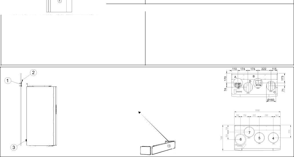
1. |
Inspektionstür |
8. |
Rohr von Dunstabzugshaube (Ø125) nur bei VR 400 |
|
|
|
DCV/B (falls angeschl.) |
2. |
Schalldämpfer am Gerät |
9. |
Flexible Rohre (nur am Gerät oder zugänglich) |
4. |
Frischlufteinlaß |
10. |
Spirorohre |
5. |
Fortluft über Dachhaube |
11. |
Diffusionsdichte Wärmedämmung, siehe sep Kapitel |
6. |
Zuluft/Auslässe |
12. |
Rohre mit Gefälle zur Aussenwand. |
7. |
Abluftventile in Nassräumen |
13. |
Etwaige Abdeckung zwischen Decke und Gerät |
Hinweis! VR 400 DCV/DE kann nur mit dem Bedienteil links geliefert werden.
Hinweis! Anbringen der Montageschiene (1) an der Wand. Die Unterkante der Montageschiene befindet sich 45mm unterhalb der Geräteoberkante. Schwingungsdämpfung (2) auf der Montageschiene und auf der Rückseite des Gerätes (3) auf Beschädigung überprüfen. Gerät einhängen und sicherstellen, daß kein direkter Kontakt zwischen dem Gerät und dem Gebäude besteht.
1. |
Inspection hatch |
8. |
Duct from cookerhood, (Ø125/ only for VR 400 DCV/B) |
2. |
Sound attenuators inlet/extract |
9. |
Flexible ducting |
4. |
Fresh air intake |
10. |
Spiro ducting |
5. |
Discharge extract air |
11. |
Condensation-/ heat insulation, see |
6. |
Air inlet/inlet diffusers |
|
separate chapter |
7. |
Extract/extract louvers |
12. |
Grade towards wall grill |
|
|
13. |
Duct cover between roof and unit, if required |
NOTE! VR 400 DCV/DE is only available as a left hand model.
NOTE!Install mounting bracket (1) on the wall. Bottom side of bracket should be 45 mm below top of unit position, when installed on the wall. Check that the anti vibration packing (2) on the mounting bracket and on the backside of the unit (3) is undamaged. Lift the unit into position and make sure that there is no direct contact between unit and building construction.
4xØ160 mm
VR 400 DCV/DE
4xØ200 mm
Fig. 1 |
VR 700 DVC/DE |
3

INSTALLATION DER ZENTRALEINHEIT (Fig. 1)
Das Zentralgerät wird vorzugsweise in einem Extraraum aufgestellt, z.B. im Hauswirtschaftsraum oder im Abstellraum. Die Geräte sind Wandgeräte können aber auch liegend mit der Front nach oben aufgestellt werden. In diesem Falle müssen Schalldämmunterlagen darunter gelegt werden.
Bei der Standortwahl denken Sie bitte an die regelmäßige Reinigung und Wartung der Anlage. Stellen Sie sicher, daß sich die Kontrolltüren zur Wartung öffnen lassen und genügend Platz zum Ausbau der Hauptkomponenten vorhanden ist. Wenn das Gerät auf einer Leichtbauwand zu einem Wohnod. Schlafzimmer hin montiert wird, ist auf die Vermeidung der Schallübertragung zu achten!
Der empfohlene Platz für die Frischluftansaugung ist die Nordoder Ostseite des Gebäudes, mit einem ausreichenden Abstand zu Abluftöffnungen wie z.B. Dunsthauben, Zentralstaubsauger, Kanalentlüftung und anderen Geruchsquellen. Denken Sie bitte auch an den Straßenverkehr. Die Fortluft sollte über die Dachhaube ins Freie geleitet werden, mit einem ausreichenden Abstand zu Fenstern und dem Frischlufeinlaß.
Eine weiße Abdeckung (13)zw. Decke und Gerät (H=295mm) ist als Zubehör erhältlich.
Die Abdeckung muß so montiert sein, daß die Revisionstür (1) entfernt werden kann: max. Tiefe VR 400 DCV = 355 mm, VR 700 DCV = 470 mm.
INSTALLING THE UNIT/POSITIONING AND ACCESS (Fig. 1)
The unit should preferably be installed in a separate room (e.g. storeroom, laundry room or similar). The unit is produced for installation on the wall, but can alternatively be installed lying (i.e. inspection door upwards). If lying installation is chosen, ensure that necessary anti vibration pads under the unit.
When choosing the installation position, consideration must be taken that the unit requires regular maintenance. Make sure that the inspection doors are available for maintenance/service. Leave free space for removing of inspection doors and main components inside the unit. If the unit is installed on a light wall construction towards a living room (f.ex. bedroom), we recommend that the wall is insulated/ designed so that transfer of noise is avoided.
Recommended installation location for the fresh air intake is the northern or eastern side of the building and with a distance to openings for discharge of stale ventilation air, kitchen ventilator, central vacuum system, waist water drainage and other pollution sources like exhaust from traffic etc. Stale discharge air should ideally be led via a roof unit to outside and with a good distance to any fresh air intake, windows etc.
White painted duct cover (13) between ceiling and unit (H=295mm) can be supplied as additional equipment. If duct cover over the unit is being built on site, ensure that it is built so that inspection hatch (1) can be removed. I.e. max. debth VR 400 DCV = 355 mm, VR 700 DCV = 470 mm.
4

1. |
Schlafen |
1. |
Bedroom |
2. |
Wohnen |
2. |
Living room |
3. |
Küche |
3. |
Kitchen |
4. |
Bad/HWR |
4. |
Bathroom/Laundry room |
5. |
Windfang |
5. |
Hall |
6. |
Abstellraum |
6. |
Storeroom |
Fig. 2
5
 Loading...