


SYSDRIVE 3G3XV Inverter
3G3XV- -EV2
Operation Manual
Revised November 1997
iv

Notice:
OMRON products are manufactured for use according to proper procedures by a qualified operator and only for the purposes described in this manual.
The following conventions are used to indicate and classify precautions in this manual. Always heed the information provided with them. Failure to heed precautions can result in injury to people or damage to the product.
! DANGER Indicates information that, if not heeded, is likely to result in loss of life or serious injury.
! WARNING Indicates information that, if not heeded, could possibly result in loss of life or serious injury.
! Caution Indicates information that, if not heeded, could result in relatively serious or minor injury, damage to the product, or faulty operation.
OMRON Product References
All OMRON products are capitalized in this manual. The word ªUnitº is also capitalized when it refers to an OMRON product, regardless of whether or not it appears in the proper name of the product.
The abbreviation ªCh,º which appears in some displays and on some OMRON products, often means ªwordº and is abbreviated ªWdº in documentation in this sense.
The abbreviation ªPCº means Programmable Controller and is not used as an abbreviation for anything else.
Visual Aids
The following headings appear in the left column of the manual to help you locate different types of information.
Note Indicates information of particular interest for efficient and convenient operation of the product.
1, 2, 3... 1. Indicates lists of one sort or another, such as procedures, checklists, etc.
OMRON, 1993
All rights reserved. No part of this publication may be reproduced, stored in a retrieval system, or transmitted, in any form, or by any means, mechanical, electronic, photocopying, recording, or otherwise, without the prior written permission of OMRON.
No patent liability is assumed with respect to the use of the information contained herein. Moreover, because OMRON is constantly striving to improve its high-quality products, the information contained in this manual is subject to change without notice. Every precaution has been taken in the preparation of this manual. Nevertheless, OMRON assumes no responsibility for errors or omissions. Neither is any liability assumed for damages resulting from the use of the information contained in this publication.
v
vi
|
TABLE OF CONTENTS |
|
SECTION 1 |
|
|
SYSDRIVE 3G3XV Inverter Main Unit . . . . . . . . |
1 |
|
1-1 Part Names of the 3G3XV . . . . . . . . . . . . . . . . . . . . . . . . . . . . . . . . . . . . . |
2 |
|
1-2 |
Receiving . . . . . . . . . . . . . . . . . . . . . . . . . . . . . . . . . . . . . . . . . . . . . . . . . . |
2 |
1-3 |
Installation . . . . . . . . . . . . . . . . . . . . . . . . . . . . . . . . . . . . . . . . . . . . . . . . . |
3 |
1-4 |
Wiring . . . . . . . . . . . . . . . . . . . . . . . . . . . . . . . . . . . . . . . . . . . . . . . . . . . . |
5 |
1-5 |
Operation . . . . . . . . . . . . . . . . . . . . . . . . . . . . . . . . . . . . . . . . . . . . . . . . . . |
16 |
1-6 |
Specifications . . . . . . . . . . . . . . . . . . . . . . . . . . . . . . . . . . . . . . . . . . . . . . . |
21 |
SECTION 2 |
|
|
Digital Operator . . . . . . . . . . . . . . . . . . . . . . . . . . . . |
27 |
|
2-1 |
Digital Operator Components . . . . . . . . . . . . . . . . . . . . . . . . . . . . . . . . . . |
28 |
2-2 |
Function/Constant Setting . . . . . . . . . . . . . . . . . . . . . . . . . . . . . . . . . . . . . |
29 |
2-3 Digital Operator Operation Example . . . . . . . . . . . . . . . . . . . . . . . . . . . . . |
31 |
|
2-4 Constant Initialization and Write-protection . . . . . . . . . . . . . . . . . . . . . . . |
33 |
|
2-5 |
Corrective Function . . . . . . . . . . . . . . . . . . . . . . . . . . . . . . . . . . . . . . . . . . |
34 |
2-6 |
Monitor . . . . . . . . . . . . . . . . . . . . . . . . . . . . . . . . . . . . . . . . . . . . . . . . . . . |
35 |
2-7 |
Function/Constant List . . . . . . . . . . . . . . . . . . . . . . . . . . . . . . . . . . . . . . . . |
37 |
2-8 Description of Functions and Constants . . . . . . . . . . . . . . . . . . . . . . . . . . |
43 |
|
SECTION 3 |
|
|
Troubleshooting and Maintenance . . . . . . . . . . . . . |
65 |
|
3-1 |
Fault Display . . . . . . . . . . . . . . . . . . . . . . . . . . . . . . . . . . . . . . . . . . . . . . . |
66 |
3-2 |
Correcting Motor Faults . . . . . . . . . . . . . . . . . . . . . . . . . . . . . . . . . . . . . . . |
69 |
3-3 |
Maintenance . . . . . . . . . . . . . . . . . . . . . . . . . . . . . . . . . . . . . . . . . . . . . . . . |
70 |
Revision History . . . . . . . . . . . . . . . . . . . . . . . . . . . . |
73 |
|
vii

About this Manual:
This manual provides operating procedures and parameter specifications for the SYSDRIVE 3G3XV All-Digital Low-Noise Inverter.
Section 1 describes handling, wiring, operation, and specifications of the SYSDRIVE 3G3XV series (hereinafter called 3G3XV).
Section 2 outlines the digital operator performance,constants, operation, etc.
Section 3 describes maintenance, periodic inspections, troubleshooting, etc.
Before using the 3G3XV, a thorough understanding of this manual is recommended.
This manual will be of great help for daily maintenance, inspection and troubleshooting.
! WARNING Failure to read and understand the information provided in this manual may result in personal injury or death, damage to the product, or product failure. Please read each section in its entirety and be sure you understand the information provided in the section and related sections before attempting any of the procedures or operations given.
ix
SECTION 1
SYSDRIVE 3G3XV Inverter Main Unit
This section describes handling, wiring, operation, and specifications of the SYSDRIVE 3G3XV series.
1-1 Part Names of the 3G3XV . . . . . . . . . . . . . . . . . . . . . . . . . . . . . . . . . . . . . |
2 |
||
1-2 |
Receiving . . . . . . . . . . . . . . . . . . . . . . . . . . . . . . . . . . . . . . . . . . . . . . . . . . |
2 |
|
1-3 |
Installation . . . . . . . . . . . . . . . . . . . . . . . . . . . . . . . . . . . . . . . . . . . . . . . . . |
3 |
|
|
1-3-1 Location . . . . . . . . . . . . . . . . . . . . . . . . . . . . . . . . . . . . . . . . . . . . . |
3 |
|
|
1-3-2 |
Mounting Space . . . . . . . . . . . . . . . . . . . . . . . . . . . . . . . . . . . . . . . |
4 |
|
1-3-3 Dimensions in Inches (mm) . . . . . . . . . . . . . . . . . . . . . . . . . . . . . . |
4 |
|
1-4 |
Wiring |
. . . . . . . . . . . . . . . . . . . . . . . . . . . . . . . . . . . . . . . . . . . . . . . . . . . . |
5 |
|
1-4-1 |
Terminal Blocks . . . . . . . . . . . . . . . . . . . . . . . . . . . . . . . . . . . . . . . |
5 |
|
1-4-2 |
Standard Wiring Diagram . . . . . . . . . . . . . . . . . . . . . . . . . . . . . . . |
7 |
|
1-4-3 |
Main Circuit . . . . . . . . . . . . . . . . . . . . . . . . . . . . . . . . . . . . . . . . . . |
8 |
|
1-4-4 |
Control Circuit . . . . . . . . . . . . . . . . . . . . . . . . . . . . . . . . . . . . . . . . |
14 |
1-5 |
Operation . . . . . . . . . . . . . . . . . . . . . . . . . . . . . . . . . . . . . . . . . . . . . . . . . . |
16 |
|
|
1-5-1 |
Checking Before Operation . . . . . . . . . . . . . . . . . . . . . . . . . . . . . . |
16 |
|
1-5-2 |
Setting Before Operation . . . . . . . . . . . . . . . . . . . . . . . . . . . . . . . . |
17 |
|
1-5-3 |
Test Run Method . . . . . . . . . . . . . . . . . . . . . . . . . . . . . . . . . . . . . . |
18 |
1-6 |
Specifications . . . . . . . . . . . . . . . . . . . . . . . . . . . . . . . . . . . . . . . . . . . . . . . |
21 |
|
|
1-6-1 |
200-V-class Specifications . . . . . . . . . . . . . . . . . . . . . . . . . . . . . . . |
21 |
|
1-6-2 |
400-V-class Specifications . . . . . . . . . . . . . . . . . . . . . . . . . . . . . . . |
23 |
|
1-6-3 |
Optional Units . . . . . . . . . . . . . . . . . . . . . . . . . . . . . . . . . . . . . . . . |
24 |
|
1-6-4 |
Peripheral Units . . . . . . . . . . . . . . . . . . . . . . . . . . . . . . . . . . . . . . . |
25 |
1
Receiving |
Section 1-2 |
|
|
|
|
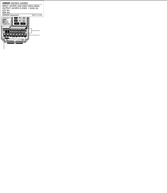
1-1 Part Names of the 3G3XV
The following diagram shows the main components of the SYSDRIVE 3G3XV. The terminal block cover has been removed to expose the terminal blocks. Refer to 1-4-1 Terminal Blocks for details on removing the terminal block cover.
Digital Operator
(Model 3G3XV-PJVOP110)
Set the operating constants with the Digital Operator. (3G3XV-series only)
Control circuit terminal block
Main circuit terminal block
CHARGE indicator
Do not touch the main circuit terminals when this indicator is lit.
1-2 Receiving
This SYSDRIVE 3G3XV has been put through demanding tests at the factory before shipment.
After unpacking, check for the following.
•Verify the part numbers with the purchase order sheet and/or packing slip.
•Transit damage.
If any part of 3G3XV is damaged or lost, immediately notify the shipper.
Nameplate Data
Inverter Model 
Input specifications 
Output specifications 
2
Installation |
Section 1-3 |
|
|
|
|
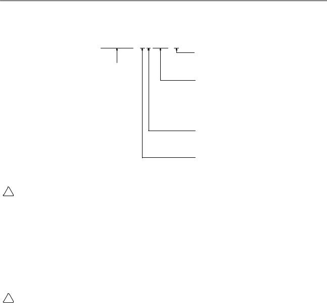
Inverter Model Numbers
3G3XV-A4002-EV2
Country
EV2: European countries
3G3XV-series (E: Old model) None:Japan
Max. Applicable Motor Capacity
001: 0.1 kW
002: 0.2 kW 004: 0.4 kW
. .
. .
. .
037: 3.7 kW
Voltage Class
2: 3-phase, 200 V
4: 3-phase, 400 V
B: Single-phase, 200 V
Protective Structure
A: Enclosed wall mounting
P: Optional structure
! WARNING
1, 2, 3... 1. After turning off the main circuit power supply, do not touch circuit components until the ªCHARGEº indicator is extinguished.
The capacitors are still charged and can be quite dangerous.
2.Do not change the wiring while power is applied to the circuit.
3.Do not check signals during operation.
4.Be sure to ground 3G3XV using the ground terminal G (E).
5.Never connect main circuit output terminals, T1 (U), T2 (V), T3 (W), to AC main circuit supply.
! Caution
1, 2, 3... 1. All the constants of 3G3XV have been adjusted at the factory. Do not change their settings unnecessarily.
2.Do not perform withstand voltage test on any part of the 3G3XV
Unit. This electronic equipment uses semi-conductors and is vulnerable to high voltage.
1-3 Installation
1-3-1 Location
Location of the equipment is important to achieve proper performance and normal operating life.
The 3G3XV Units should be installed in areas where the following conditions exist.
•Ambient temperature:
±10° to 40°C, 14° to 104°F (with top cover on) ±10° to 45°C, 14° to 113°F (with top cover off)
•Protected from rain or moisture.
3

Installation |
Section 1-3 |
|
|
|
|
•Protected from direct sunlight.
•Protected from corrosive gases or liquids.
•Free from airborne dust or metallic particles.
•Free from vibration.
•Free from magnetic noise.
! Caution To house multiple SYSDRIVE 3G3XVs in a switchgear, install a cooling fan or some other means to cool the air entering the
Inverter below 113°F (45°C).
1-3-2 Mounting Space
1.18 in (30 mm)
OR MORE
Install the 3G3XV vertically and allow sufficient space for effective cooling as shown in below.
1.18 in (30 mm)
OR MORE
3.94 in (100 mm) OR MORE
|
3.94 in (100 mm) OR MORE |
|
(a) Front View. |
(b) Side View |
|
1-3-3 Dimensions in Inches (mm)
The Unit dimensions vary from model to model, as shown in the following diagram and table.
4
Wiring |
Section 1-4 |
|
|
|
|
H1 H
|
|
|
|
|
Four, d dia. |
|
|
D |
|
|
|
|
|
|
W |
|
|
|
|
|
|||
|
|
|
|
|
|
|
|
|
|||
|
|
|
|
|
|
|
|
|
|
||
Voltage |
Phase |
Max. Applicable |
|
W |
W1 |
H |
H1 |
D |
d |
||
|
|
Motor Output HP (kW) |
|
|
|
|
|
|
|||
200 V |
3-phase |
0.13 to 0.5 (0.1 to 0.4) |
|
4.13 |
3.66 |
5.91 |
5.43 |
3.94 |
0.20 |
||
|
|
|
|
|
|
(105) |
(93) |
(150) |
(138) |
(100) |
(5) |
|
|
1/2 (0.75/1.5) |
|
|
5.51 |
5.04 |
5.91 |
5.43 |
5.43 |
0.20 |
|
|
|
|
|
|
|
(140) |
(128) |
(150) |
(138) |
(138) |
(5) |
|
|
3/5 (2.2/3.7) |
|
|
5.51 |
4.96 |
7.87 |
7.32 |
6.69 |
0.22 |
|
|
|
|
|
|
|
(140) |
(126) |
(200) |
(186) |
(170) |
(5.5) |
|
|
|
|
|
|
|
|
|
|
||
|
Single-phase |
0.13 to 0.5 (0.1 to 0.4) |
|
5.51 |
5.04 |
5.91 |
5.43 |
5.43 |
0.20 |
||
|
|
|
|
|
|
(140) |
(128) |
(150) |
(138) |
(138) |
(5) |
|
|
1/2 (0.75/1.5) |
|
|
5.51 |
4.96 |
7.87 |
7.32 |
6.69 |
0.22 |
|
|
|
|
|
|
|
(140) |
(126) |
(200) |
(186) |
(170) |
(5.5) |
|
|
|
|
|
|
|
|
|
|
|
|
|
|
3/5 (2.2/3.7) |
|
|
7.48 |
6.89 |
7.87 |
7.28 |
7.48 |
0.23 |
|
|
|
|
|
|
|
(190) |
(175) |
(200) |
(185) |
(190) |
(5.8) |
|
|
|
|
|
|
|
|
|
|
||
400 V |
3-phase |
0.25/0.5 (0.2/0.4) |
|
5.51 |
4.96 |
7.87 |
7.32 |
4.72 |
0.22 |
||
|
|
|
|
|
|
(140) |
(126) |
(200) |
(186) |
(120) |
(5.5) |
|
|
1/2 (0.75/1.5) |
|
|
5.51 |
4.96 |
7.87 |
7.32 |
6.69 |
0.22 |
|
|
|
|
|
|
|
(140) |
(126) |
(200) |
(186) |
(170) |
(5.5) |
|
|
|
|
|
|
|
|
|
|
|
|
|
|
3/5 (2.2/3.7) |
|
|
7.48 |
6.89 |
7.87 |
7.28 |
7.48 |
0.23 |
|
|
|
|
|
|
|
(190) |
(175) |
(200) |
(185) |
(190) |
(5.8) |
1-4 Wiring
Connect the main circuit and control circuit wiring securely, as described below.
Note Use closed-loop connectors sized for the gauge of wire being used. Attach the connectors using a crimping tool recommended by the connector manufacturer.
1-4-1 Terminal Blocks
The main circuit and control circuit terminal blocks are at the bottom of the Inverter under a terminal cover.
Removing/Attaching the Terminal Cover
To remove the terminal cover, squeeze the sides of the cover (1), and lift up (2) at the same time, as shown in the following diagram. Reverse these steps to attach the cover.
5

Wiring |
Section 1-4 |
|
|
|
|
(1)
(2)
(1)
Terminal Position
The main circuit and control circuit terminal blocks are shown below. Terminal numbers are usually shown on the terminal number nameplate, but the terminal numbers are printed on the printed board on some Inverters.
Fault signal output terminal
(FLT± A, B, C) Main circuit terminal block
Control circuit
terminal block
CHARGE indicator
Grounding terminal
6

Wiring |
Section 1-4 |
|
|
|
|
1-4-2 Standard Wiring Diagram
Models with Digital Operators can be operated from the Digital
Operator only by main circuit wiring. When these models are operated by control circuit terminals, control constant change is required. For details refer to 2-8-2 Operation Mode Selection. Models without Digital Operator (with blind cover) are preset in Operation Mode from control circuit terminals at the factory prior to shipping.
Main circuit |
Braking resistor (optional) |
|
power supply |
||
|
Only terminal L1(R), L2(S) for single-phase power supply
|
MCCB |
B1/(+) |
|
B2 |
|
|
|
|
|
L1 (R) |
L1 (R) |
|
T1 (U) |
|
L2 (S) |
L2 (S) |
|
T2 (V) |
|
L3 (T) |
L3 (T) |
|
T3 (W) |
|
|
|
3G3XV |
|
G (E) |
Forward |
|
|
|
|
|
|
|
|
|
Run/Stop |
1 |
|
|
|
Reverse |
|
|
|
|
|
|
|
12 |
|
Run/Stop |
2 |
|
|
|
|
|
|
||
|
|
Analog monitor |
||
|
|
|
||
|
|
|
|
11 |
Fault reset |
3 |
|
|
|
External fault |
|
|
FL T-A |
|
4 |
|
|
||
Multi-step speed |
Multifunction contact input |
|
||
|
FL T-B |
|||
setting 1 |
5 |
|
|
|
|
|
|
||
|
|
|
|
FL T-C |
|
6 |
Sequence common terminal (0v) |
||
G (E)
Shielded lead connection terminal
IM
|
FM |
Analog output |
|
|
0 to + 10 VDC. |
|
|
(Factory setting is |
|
|
output frequency) |
Fault contact output contact capacity: less than 1 A for
250 VAC and 30 VDC
|
2KΩ |
|
|
2KΩ |
0 to +10 VDC |
||
4 to 20 mA |
|||
|
|||
|
P |
P |
|
10 |
Power supply for speed setting: |
|
+12 V 20 mA |
||
|
||
8 Master command |
||
9 |
0 to +10 VDC(2 KΩ) |
|
Current command |
||
|
||
|
4 to 20 mA(250 Ω) |
|
|
11 |
|
|
0V |
|
13 |
|
|
|
During run |
|
|
|
Multlfunction |
14 |
|
output open |
|
collector less |
|
|
|
|
|
Frequency |
than 48 V 50 mA |
7 |
agreement |
|
|
Standard Wiring Diagram |
|
|
|
P |
Note 1. |
indicates shielded leads. |
indicates twisted-pair |
|
shielded leads. |
|
2.Terminal 10 (12 VDC) has a maximum output current capacity of 20 mA.
3.Terminal symbols:  indicates the main circuit, and
  indicates the control circuit.
7

Wiring |
Section 1-4 |
|
|
|
|
4.When using the optional braking resistor (3G3IV-
PERF150WJ), place a thermal overload relay between the braking resistor and Inverter to prevent the braking resistor from overheating. In addition, use a sequencer to break the power supply side on the thermal overload relay trip contact.
1-4-3 Main Circuit
Main Circuit Wiring
Connect wiring as shown below.
Braking resistor or
Braking Resistor Unit (optional)
|
|
MCCB |
|
|
B1/ B2 |
|
Motor |
|
L1 |
(R) |
L1 |
(R) |
T1 |
(U) |
|||
|
||||||||
L2 |
(S) |
L2 |
(S) |
3G3XV T2 |
(V) |
IM |
||
L3 |
(T) |
L3 |
(T) |
T3 |
(W) |
|
||
3-phase power supply |
|
|
G(E) |
|
||||
|
|
|
|
|
||||
200 to 230 |
VAC, 50/60 Hz, |
|
|
|
|
|
||
380 to 460 |
VAC, 50/60 Hz |
|
|
|
|
|
||
Only terminal L1 (R), L2 (S) for single-phase power supply
Note Circuit terminal block screw size is M4
Main Circuit Terminals
3G3XV Main Circuit Terminals
Terminal |
|
Description |
|
|
|
|
|
L1 |
(R) |
Main circuit power input |
|
L2 |
(S) |
ªLº and ªLº are used for single-phase input specifications. |
|
1 |
2 |
||
L3 |
(T) |
|
|
T1 |
(U) |
Inverter output |
|
T2 |
(V) |
|
|
T3 |
(W) |
|
|
B1/ |
Braking resistor or Braking Resistor Unit connector (options) |
||
B2 |
|
|
|
|
|
||
G (E) |
Grounding (Ground resistance should be 100 ohms or less.) |
||
|
|
Note: Use screw for frame ground. |
|
Main Circuit Terminal Arrangement
3-phase series (all Models):
L1 |
L2 |
L3 |
B1/ |
B2 |
T1 |
T2 |
T3 |
(R) |
(S) |
(T) |
|
|
(U) |
(V) |
(W) |
200-V single-phase series, 0.13 to 2 HP (0.1 to 1.5 kW):
L1 |
L2 |
|
B1/ |
B2 |
T1 |
T2 |
T3 |
(R) |
(S) |
|
|
|
(U) |
(V) |
(W) |
Note The third terminal is blank.
8

Wiring |
Section 1-4 |
|
|
|
|
200-V single-phase series, 3/5 HP (2.2/3.7 kW):
L1 |
L2 |
B1/ |
B2 |
T1 |
T2 |
T3 |
(R) |
(S) |
|
|
(U) |
(V) |
(W) |
Molded-case Circuit Breaker (MCCB)
Be sure to connect MCCBs between the power supply and 3G3XV input terminals L1 (R), L2 (S), L3 (T). Recommended MCCBs are listed in the tables below.
When a ground fault interrupter is used select the one with no influence for high frequency. When using an ordinary type, the setting current should be 200 mA or over per Unit and operating time,
0.1 sec or over to prevent malfunction.
Molded-case Circuit Breakers and Magnetic Contactors
200-V-class 3-phase Input Series:
|
Model |
A2001 |
A2002 |
A2004 |
|
A2007 |
|
A2015 |
|
A2022 |
|
A2037 |
||||
3G3XV |
3G3XV- -EV2 |
|
|
|
|
|
|
|
|
|
|
|
|
|
|
|
|
|
|
|
|
|
|
|
|
|
|
|
|
|
|
|
|
Capacity (kVA) |
0.3 |
0.6 |
1.1 |
|
1.9 |
|
|
2.5 |
|
|
4.2 |
|
6.7 |
|||
|
|
|
|
|
|
|
||||||||||
|
|
|
|
|
|
|
|
|
|
|
|
|
|
|
|
|
|
Rated output current (A) |
0.8 |
1.5 |
3 |
|
|
5 |
|
|
6.5 |
|
|
11 |
|
17.5 |
|
|
|
|
|
|
|
|
|
|
|
|
|
|
|
|
|
|
Molded-case Circuit Breakers |
5 A |
5 A |
5 A |
|
10 A |
|
20 A |
|
|
20 A |
|
30 A |
||||
|
200-V-class Single-phase Input Series: |
|
|
|
|
|
|
|||||||||
|
|
|
|
|
|
|
|
|
|
|
|
|
|
|||
|
Model |
AB001 |
AB002 |
AB004 |
|
AB007 |
|
AB015 |
|
AB022 |
|
AB037 |
||||
3G3XV |
3G3XV- -EV2 |
|
|
|
|
|
|
|
|
|
|
|
|
|
|
|
|
|
|
|
|
|
|
|
|
|
|
|
|
|
|
|
|
Capacity (kVA) |
0.3 |
0.6 |
1.1 |
|
1.9 |
|
|
2.5 |
|
|
4.2 |
|
6.7 |
|||
|
|
|
|
|
|
|
||||||||||
|
|
|
|
|
|
|
|
|
|
|
|
|
|
|
|
|
|
Rated output current (A) |
0.8 |
1.5 |
3 |
|
|
5 |
|
|
6.5 |
|
|
11 |
|
17.5 |
|
|
|
|
|
|
|
|
|
|
|
|
|
|
|
|
|
|
Molded-case Circuit Breakers |
5 A |
5 A |
10 A |
|
20 A |
|
20 A |
|
|
40 A |
|
50 A |
||||
|
400-V-class 3-phase Input Series: |
|
|
|
|
|
|
|||||||||
|
|
|
|
|
|
|
|
|
|
|
||||||
|
Model |
A4002 |
|
A4004 |
|
A4007 |
|
A4015 |
A4022 |
A4037 |
||||||
3G3XV |
3G3XV- -EV2 |
|
|
|
|
|
|
|
|
|
|
|
|
|
|
|
|
|
|
|
|
|
|
|
|
|
|
|
|
|
|
|
|
Capacity (kVA) |
0.8 |
|
1.2 |
|
2.0 |
|
|
3.0 |
|
|
3.7 |
|
6.1 |
|||
|
|
|
|
|
|
|
|
|||||||||
|
|
|
|
|
|
|
|
|
|
|
|
|
|
|
||
|
Rated output current (A) |
1 |
|
1.6 |
|
2.6 |
|
|
4 |
|
|
4.8 |
|
8 |
||
|
|
|
|
|
|
|
|
|
|
|
|
|||||
Molded-case Circuit Breakers |
5 A |
|
5 A |
|
5 A |
|
10 A |
|
10 A |
20 A |
||||||
Surge Absorber
The surge absorbers should be connected to the coils of relays, magnetic contactors, magnetic valves, or magnetic relays. Select the type from the table below.
Surge Absorbers
Coils of magnetic contactor and control relay |
Surge absorber (see note) |
||||
|
|
|
|
|
|
|
|
Model |
|
Specifications |
|
|
|
|
|
|
|
200 to 230 V |
Large-size magnetic contactors |
DCR2-50A22E |
250 |
VAC, 0.5 |
μF + 20 Ω |
|
Control relay |
DCR2-10A25C |
250 |
VAC, 0.1 |
μF + 100 Ω |
|
LY-2, -3 (OMRON) |
|
|
|
|
|
MM-2, -4 (OMRON) |
|
|
|
|
|
|
|
|
||
400to 460-V Units |
DCR2-50D100B |
1,000 VDC, 0.5 μF + 220 Ω |
|||
Note Made by MARCON Electronics. Marketed in Japan.
9

Wiring |
Section 1-4 |
|
|
|
|
Wiring
Main Circuit Input/Output
•Phase rotation of input terminals L1 (R), L2 (S), L3 (T) is available in either direction, clockwise and counterclockwise.
•When Inverter output terminals T1 (U), T2 (V), and T3 (W) are connected to motor terminals T1 (U), T2 (V), and T3 (W), respectively, motor rotates counterclockwise, viewed from opposite drive end, upon forward operation command. To reverse the rotation interchange any two of motor leads.
•Never connect AC main circuit power supply to output terminals
T1 (U), T2 (V), and T3 (W).
•Care should be taken to prevent contact of wiring leads with the 3G3XV cabinet, or a short-circuit may result.
•Never connect the power factor correction capacitor or noise filter to 3G3XV output.
•Never open or close contactors in the output circuit unless
Inverter is properly sized.
! Caution The withstand voltage between the motor's phases is insufficient.
When the motor is connected to the Inverter's output, a surge is generated between the Inverter's switching and the motor's coil.
Normally the maximum surge voltage is three times the Inverter's input power supply voltage (i.e., 600 V for 200-V class, and
1,200 V for 400-V class). Be sure to use a motor with a withstand voltage between the motor's phases that is greater than the maximum surge voltage. In particular, when using a 400-V-class
Inverter, use a special motor for Inverters.
10

Wiring |
Section 1-4 |
|
|
|
|
Wire Sizes and Types
200-V-class 3-phase Input Series:
Circuit |
Model |
Inverter |
Terminal symbol |
Terminal |
Wire size |
Wire type |
|
|
3G3XV |
capacity |
|
screw |
|
|
|
|
|
AWG |
mm2 |
|
|||
Main |
A2001 |
0.3 kVA |
L1 (R), L2 (S), L3 (T), B1/ , |
M4 |
14-10 |
2 to 5.5 |
Power cable: |
circuit |
|
|
B2, T1 (U), T2 (V), T3 (W) |
|
|
|
600 V |
|
|
|
|
|
|
|
vinyl-sheathed |
|
|
|
G (E) |
|
14-10 |
2 to 5.5 |
|
|
|
|
|
lead or |
|||
|
|
|
|
|
|
|
|
|
A2002 |
0.6 kVA |
L1 (R), L2 (S), L3 (T), B1/ , |
M4 |
14-10 |
2 to 5.5 |
|
|
equivalent |
||||||
|
|
|
B2, T1 (U), T2 (V), T3 (W) |
|
|
|
|
|
|
|
|
|
|
|
|
|
|
|
G (E) |
|
14-10 |
2 to 5.5 |
|
|
|
|
|
|
|
|
|
|
A2004 |
1.1 kVA |
L1 (R), L2 (S), L3 (T), B1/ , |
M4 |
14-10 |
2 to 5.5 |
|
|
|
|
B2, T1 (U), T2 (V), T3 (W) |
|
|
|
|
|
|
|
G (E) |
|
14-10 |
2 to 5.5 |
|
|
|
|
|
|
|
|
|
|
A2007 |
1.9 kVA |
L1 (R), L2 (S), L3 (T), B1/ , |
M4 |
14-10 |
2 to 5.5 |
|
|
|
|
B2, T1 (U), T2 (V), T3 (W) |
|
|
|
|
|
|
|
G (E) |
|
14-10 |
2 to 5.5 |
|
|
|
|
|
|
|
|
|
|
A2015 |
2.5 kVA |
L1 (R), L2 (S), L3 (T), B1/ , |
M4 |
12-10 |
3.5 to 5.5 |
|
|
|
|
B2, T1 (U), T2 (V), T3 (W) |
|
|
|
|
|
|
|
G (E) |
|
14-10 |
2 to 5.5 |
|
|
|
|
|
|
|
|
|
|
A2022 |
4.2 kVA |
L1 (R), L2 (S), L3 (T), B1/ , |
M4 |
12-10 |
3.5 to 5.5 |
|
|
|
|
B2, T1 (U), T2 (V), T3 (W) |
|
|
|
|
|
|
|
G (E) |
|
14-10 |
2 to 5.5 |
|
|
|
|
|
|
|
|
|
|
A2037 |
6.7 kVA |
L1 (R), L2 (S), L3 (T), B1/ , |
M4 |
12-10 |
3.5 to 5.5 |
|
|
|
|
B2, T1 (U), T2 (V), T3 (W) |
|
|
|
|
|
|
|
G (E) |
|
14-10 |
2 to 5.5 |
|
|
|
|
|
|
|
|
|
Control |
Common |
±±± |
1 to 14, |
M3.5 |
20-14 |
0.5 to 2 |
Shielded lead |
circuit |
to all |
|
FLT-A, FLT-B, FLT-C |
|
|
|
or equivalent |
|
Models |
|
|
|
|
|
|
|
|
G (E) |
|
|
|
|
|
|
|
|
|
|
|
|
|
200-V-class Single-phase Input Series:
Circuit |
Model |
Inverter |
Terminal symbol |
Terminal |
Wire size |
Wire type |
|
|
3G3XV |
capacity |
|
screw |
|
|
|
|
|
AWG |
mm2 |
|
|||
Main |
AB001 |
0.3 kVA |
L1 (R), L2 (S), B1/ , B2, T1 |
M4 |
14-10 |
2 to 5.5 |
Power cable: |
circuit |
|
|
(U), T2 (V), T3 (W) |
|
|
|
600 V |
|
|
|
|
|
|
|
vinyl-sheathed |
|
|
|
G (E) |
|
14-10 |
2 to 5.5 |
|
|
|
|
|
lead or |
|||
|
|
|
|
|
|
|
|
|
AB002 |
0.6 kVA |
L1 (R), L2 (S), B1/ , B2, T1 |
M4 |
14-10 |
2 to 5.5 |
|
|
equivalent |
||||||
|
|
|
(U), T2 (V), T3 (W) |
|
|
|
|
|
|
|
|
|
|
|
|
|
|
|
G (E) |
|
14-10 |
2 to 5.5 |
|
|
|
|
|
|
|
|
|
|
AB004 |
1.1 kVA |
L1 (R), L2 (S), B1/ , B2, T1 |
M4 |
14-10 |
2 to 5.5 |
|
|
|
|
(U), T2 (V), T3 (W) |
|
|
|
|
|
|
|
G (E) |
|
14-10 |
2 to 5.5 |
|
|
|
|
|
|
|
|
|
|
AB007 |
1.9 kVA |
L1 (R), L2 (S), B1/ , B2, T1 |
M4 |
14-10 |
2 to 5.5 |
|
|
|
|
(U), T2 (V), T3 (W) |
|
|
|
|
|
|
|
G (E) |
|
14-10 |
2 to 5.5 |
|
11

Wiring |
|
|
|
|
|
|
Section 1-4 |
|
|
|
|
|
|
|
|
|
|
Circuit |
Model |
Inverter |
Terminal symbol |
Terminal |
Wire size |
Wire type |
||
|
3G3XV |
capacity |
|
screw |
|
|
|
|
|
|
AWG |
mm2 |
|
|
|||
Main |
AB015 |
2.5 kVA |
L1 (R), L2 (S), B1/ , B2, T1 |
M4 |
14-10 |
2 to 5.5 |
Power cable: |
|
circuit |
|
|
(U), T2 (V), T3 (W) |
|
|
|
600 V |
|
|
|
|
|
|
|
|
vinyl-sheathed |
|
|
|
|
G (E) |
|
14-10 |
2 to 5.5 |
||
|
|
|
|
lead or |
||||
|
|
|
|
|
|
|
||
|
AB022 |
4.2 kVA |
L1 (R), L2 (S), B1/ , B2, T1 |
M5 |
12-8 |
3.5 to 8 |
||
|
equivalent |
|||||||
|
|
|
(U), T2 (V), T3 (W) |
|
|
|
||
|
|
|
|
|
|
|
|
|
|
|
|
G (E) |
|
14-8 |
2 to 8 |
|
|
|
|
|
|
|
|
|
|
|
|
AB037 |
6.7 kVA |
L1 (R), L2 (S), B1/ , B2, T1 |
M5 |
10-8 |
5.5 to 8 |
|
|
|
|
|
(U), T2 (V), T3 (W) |
|
|
|
|
|
|
|
|
G (E) |
|
14-8 |
2 to 8 |
|
|
|
|
|
|
|
|
|
|
|
Control |
Common |
±±± |
1 to 14, |
M3.5 |
20-14 |
0.5 to 2 |
Shielded lead |
|
circuit |
to all |
|
FLT-A, FLT-B, FLT-C |
|
|
|
or equivalent |
|
|
Models |
|
|
|
|
|
|
|
|
|
G (E) |
|
|
|
|
|
|
|
|
|
|
|
|
|
|
|
|
|
|
400-V-class 3-phase Input Series: |
|
|
|
|
|
|
|
|
|
|
|
|
|
|
Circuit |
Model |
Inverter |
Terminal symbol |
Terminal |
Wire size |
Wire type |
||
|
3G3XV |
capacity |
|
screw |
|
|
|
|
|
|
AWG |
mm2 |
|
|
|||
Main |
A4002 |
0.8 kVA |
L1 (R), L2 (S), L3 (T), B1/ , |
M4 |
14-10 |
2 to 5.5 |
Power cable: |
|
circuit |
|
|
B2, T1 (U), T2 (V), T3 (W) |
|
|
|
600 V |
|
|
|
|
|
|
|
|
vinyl-sheathed |
|
|
|
|
G (E) |
|
14-10 |
2 to 5.5 |
||
|
|
|
|
lead or |
||||
|
|
|
|
|
|
|
||
|
A4004 |
1.2 kVA |
L1 (R), L2 (S), L3 (T), B1/ , |
M4 |
14-10 |
2 to 5.5 |
||
|
equivalent |
|||||||
|
|
|
B2, T1 (U), T2 (V), T3 (W) |
|
|
|
||
|
|
|
|
|
|
|
|
|
|
|
|
G (E) |
|
14-10 |
2 to 5.5 |
|
|
|
|
|
|
|
|
|
|
|
|
A4007 |
2.0 kVA |
L1 (R), L2 (S), L3 (T), B1/ , |
M4 |
14-10 |
2 to 5.5 |
|
|
|
|
|
B2, T1 (U), T2 (V), T3 (W) |
|
|
|
|
|
|
|
|
G (E) |
|
14-10 |
2 to 5.5 |
|
|
|
|
|
|
|
|
|
|
|
|
A4015 |
3.0 kVA |
L1 (R), L2 (S), L3 (T), B1/ , |
M4 |
14-10 |
2 to 5.5 |
|
|
|
|
|
B2, T1 (U), T2 (V), T3 (W) |
|
|
|
|
|
|
|
|
G (E) |
|
14-10 |
2 to 5.5 |
|
|
|
|
|
|
|
|
|
|
|
|
A4022 |
3.7 kVA |
L1 (R), L2 (S), L3 (T), B1/ , |
M4 |
14-10 |
2 to 5.5 |
|
|
|
|
|
B2, T1 (U), T2 (V), T3 (W) |
|
|
|
|
|
|
|
|
G (E) |
|
14-10 |
2 to 5.5 |
|
|
|
|
|
|
|
|
|
|
|
|
A4037 |
6.1 kVA |
L1 (R), L2 (S), L3 (T), B1/ , |
M4 |
14-10 |
2 to 5.5 |
|
|
|
|
|
B2, T1 (U), T2 (V), T3 (W) |
|
|
|
|
|
|
|
|
G (E) |
|
14-10 |
2 to 5.5 |
|
|
|
|
|
|
|
|
|
|
|
Control |
Common |
±±± |
1 to 14, |
M3.5 |
20-14 |
0.5 to 2 |
Shielded lead |
|
circuit |
to all |
|
FLT-A, FLT-B, FLT-C |
|
|
|
or equivalent |
|
|
Models |
|
|
|
|
|
|
|
|
|
G (E) |
|
|
|
|
|
|
|
|
|
|
|
|
|
|
|
12

Wiring |
Section 1-4 |
|
|
|
|
! Caution Observe the following guidelines when wiring.
•Lead size should be determined considering voltage drop of leads. Select the lead size so that the voltage drop will be within
2% of the normal rated voltage. The voltage drop can be obtained from the lead resistance (R) in W/km, wiring distance (D) in meters, and current (I) in A using the following equation:
Phase-to-phase voltage drop in volts = √ 3 ×R ×D ×I ×10±3
•Insertion of AC reactor:
When the power supply capacity exceeds 600 kVA, connect an AC reactor at the Inverter input side for power supply coordination. This reactor is also effective in improving the power factor of the power supply.
•Wiring length between Inverter and motor:
If the total wiring distance between the Inverter and motor is excessively long and the Inverter carrier frequency (main transistor switching frequency) is high, harmonic leakage current from the cable will increase to affect the Inverter Unit or peripheral devices. If the wiring distance between the Inverter and motor is long, reduce the Inverter carrier frequency as shown below. The carrier frequency can be set with constant No. 40. For details, refer to 2-8-18 Carrier Frequency. The carrier frequency is set to 10 kHz at the factory prior to shipping.
Wiring distance between Inverter and motor |
Up to 30 m |
Up to 50 m |
Up to 100 m |
Over 100 m |
|
|
|
|
|
Allowable carrier frequency |
15 kHz max. |
10 kHz max. |
5 kHz max. |
2.5 kHz max. |
(Corresponding setting for constant no. 40) |
(6) |
(4) |
(2) |
(1) |
Grounding |
Ground the casing of the 3G3XV using ground terminal G (E). |
|
|
•Ground resistance should be 100 W or less. |
|
|
•Never ground the 3G3XV in common with welding machines, |
|
|
motors, and other large-current electrical equipment, or ground |
|
|
pole. Run the ground lead in a separate conduit from leads for |
|
|
large-current electrical equipment. |
|
|
•Use the ground leads which comply with AWG standards and |
|
|
make the length as short as possible. |
|
|
•Where several 3G3XV Units are used side by side, all the Units |
|
|
should preferably be grounded directly to the ground poles. How- |
|
|
ever, connecting all the ground terminals of 3G3XV in parallel, |
|
|
and grounding only one of 3G3XV to the ground pole is also per- |
|
|
missible as shown below. However, do not form a loop with the |
|
|
ground leads. |
|
|
Good |
Poor |
(a) |
(b) |
13

Wiring |
Section 1-4 |
|
|
|
|
1-4-4 Control Circuit
Control Circuit Wiring
Main circuit power supply
The control signals are connected by screws. The following figure shows the relationship between I/O signals (factory preset values) and screw terminal numbers. The terminal functions shown in the figure indicate standard setting prior to shipping. Since Operation Mode from the Digital Operator is set for the Model with the Digital
Operator, it is necessary to change the control constants when operation is performed from the control circuit terminals. For details, refer to 2-8-2 Operation Mode Selection.
Braking resistor (optional)
Only terminal L1(R), L2(S) for single-phase power supply
|
MCCB |
B1/(+) |
|
B2 |
|
|
|
|
|
L1 (R) |
L1 (R) |
|
T1 (U) |
|
L2 (S) |
L2 (S) |
|
T2 (V) |
|
L3 (T) |
L3 (T) |
|
T3 (W) |
|
|
|
3G3XV |
|
G (E) |
Forward |
|
|
|
|
|
|
|
|
|
Run/Stop |
1 |
|
|
|
Reverse |
|
|
|
|
|
|
|
12 |
|
Run/Stop |
2 |
|
|
|
|
|
|
||
|
|
Analog monitor |
||
|
|
|
||
|
|
|
|
11 |
Fault reset |
3 |
|
|
|
External fault |
|
|
FL T-A |
|
4 |
|
|
||
Multi-step speed |
Multifunction contact input |
|
||
|
FL T-B |
|||
setting 1 |
5 |
|
|
|
|
|
|
||
|
|
|
|
FL T-C |
|
6 |
Sequence common terminal (0v) |
||
G (E)
Shielded lead connection terminal
IM
|
FM |
Analog output |
|
|
0 to + 10 VDC. |
|
|
(Factory setting is |
|
|
output frequency) |
Fault contact output contact capacity: less than 1 A for
250 VAC and 30 VDC
|
2KΩ |
|
10 Power supply for speed setting: |
|
|
|
|
|
|
|
13 |
|
|
||
2KΩ |
0 to +10 VDC |
8 |
+12 V 20 mA |
|
|
||
Master command |
|
During run |
|
||||
|
|
|
|
|
|||
|
4 to 20 mA |
9 |
0 to +10 VDC(2 KΩ) |
|
|
Multlfunction |
|
|
|
|
|
Current command |
|
|
|
|
P |
P |
|
4 to 20 mA(250 Ω) |
14 |
|
output open |
|
|
|
|
11 |
|
|
collector less |
|
|
|
|
|
Frequency |
than 48 V 50 mA |
|
|
|
|
|
0V |
|
||
|
|
|
|
7 |
agreement |
|
|
|
|
|
|
Standard Wiring Diagram |
|
|
|
|
|
|
|
|
|
P |
|
Note 1. |
indicates shielded leads. |
indicates twisted-pair |
|
shielded leads. |
|
2.Terminal symbols:  indicates the main circuit, and
  indicates the control circuit.
14
Wiring Section 1-4
Control Circuit (Terminals Factory Preset)
Control Circuit Terminal Functions
Classification |
Terminal |
Signal name |
Function |
Signal level |
|
|
|
|
|
|
|
Sequence |
1 |
Forward run/stop signal |
Forward run when ªclosedº, |
Photo-coupler |
|
Input Signal |
|
|
stop when ªopenº. |
insulation input |
|
|
|
|
|
|
24 VDC 8 mA |
|
2 |
Reverse run/stop signal |
Reverse run when ªclosedº, |
||
|
|
||||
|
|
|
stop when ªopenº. |
|
|
|
|
|
|
|
|
|
3 |
Fault reset signal |
Reset when ªclosedº. |
|
|
|
|
|
|
|
|
|
4 |
External fault |
External fault when ªclosedº. |
|
|
|
|
|
|
|
|
|
5 |
Multi-step speed ref. 1 |
Multi-step |
Multifunction |
|
|
|
|
speed ref. 1 |
contact input: |
|
|
6 |
Sequence control input |
effective |
two signals |
|
|
|
common terminal |
|
available to |
|
|
|
|
|
select1 |
|
Analog Input |
10 |
Power supply terminal |
Speed ref. power supply |
12 V (Allowable |
|
Signal |
|
for frequency setting |
|
|
current 20 mA max.) |
|
|
|
|
|
|
|
8 |
Frequency ref. |
0 to 10 V/Max. output |
0 to 10 V (20 kΩ) |
|
|
|
|
frequency |
|
|
|
9 |
|
4 to 20 mA/Max. output |
4 to 20 mA (250 Ω) |
|
|
|
|
frequency |
|
|
|
11 |
Common terminal for |
0 V |
|
±±± |
|
|
control circuit |
|
|
|
Sequence |
13 |
During running |
ªLº level at run |
Multifunction |
Photo-coupler output |
Output Signal |
|
|
|
contact input: |
48 V, 50 mA max. |
14 |
Frequency agreed |
ªLº level at set |
|||
|
|
signal |
frequency = |
two signals |
|
|
|
available to |
|
||
|
|
|
output |
|
|
|
|
|
select2 |
|
|
|
|
|
frequency |
|
|
|
|
|
|
|
|
|
7 |
Photo-coupler output |
±±± |
|
|
|
|
common |
|
|
|
|
FLT-A |
Fault signal contact |
ªClosedº between A and C at |
Contact capacity |
|
|
|
output |
fault |
|
250 VAC: 1 A max. |
|
FLT-B |
|
|||
|
|
ªOpenº between B and C at |
30 VDC: 1 A max. |
||
|
|
|
|||
|
FLT-C |
Fault signal contact |
|||
|
fault |
|
|
||
|
|
output common |
|
|
|
|
|
|
|
|
|
|
|
|
|
|
|
Analog Output |
12 |
Frequency meter |
0 to 10 V/Max. output |
0 to 11 V max. |
|
Signal |
|
|
frequency. |
|
2 mA or less |
|
11 |
Common |
Possible to select current |
|
|
|
|
|
meter output.3 |
|
|
Note 1. For details refer to 2-8-14 Multifunction Contact Input Function Selection.
2.For details refer to 2-8-15 Multifunction Output Function.
3.For details refer to 2-8-9 Multifunction Analog Output Monitor.
Control Circuit Terminal Arrangement
8 |
9 |
10 |
11 |
12 |
13 |
14 |
FLT FLT FLT 1 |
2 |
3 |
4 |
5 |
6 |
7 |
A B C |
|
|
|
|
|
|
15

Operation |
Section 1-5 |
|
|
|
|
Precautions for Control Circuit Wiring
Take the following precautions when wiring.
1, 2, 3... 1. Separate the control signal line from power lines. Otherwise a malfunction might occur.
2.For the frequency setting signal (analog), use a shielded lead and be sure that the signal is terminated properly.
Connect shielded sheath to main circuit grounding terminal G (E).
Shielded Armor sheath
Never connect
Insulate these parts with insulating tape
3.The wiring length of the control signal line must be 50 m or less.
4.To drive the contact input signal by transistor, use one having
ratings of 50 V 50 mA or more. Circuit leakage current at signal OFF must be 100 μA or less.
5.To drive an inductive load (relay coil, etc.) by multifunction pho- to-coupler output, be sure to insert a free wheel diode.
|
50 mA max. |
48 V max. |
|
13.14 |
|
= |
|
Free wheel diode |
|
|
|
3G3XV |
7 |
(100V, 100 mA or more) |
|
||
|
|
1-5 Operation
1-5-1 Checking Before Operation
Check the following items after completion of installation and wiring:
•No fault in wiring. Especially, the power supply is connected to the output terminals T1 (U), T2 (V), and T3 (W).
•No short-circuit because of wiring contamination (dust, oil, etc.).
•Screws and terminals are not loosened. Wiring is provided properly.
•Wiring is not grounded.
•Load status is good.
For safe operation, before operation, the motor must be able to operate alone by separating it from the coupling or belt which connects the motor and machine.
When the motor is operated with the machine directly connected, pay close attention.
16

Operation |
Section 1-5 |
|
|
|
|
1-5-2 Setting Before Operation
Set Value Prior to Shipping
Since the standard Inverter Models are shipped with the default values listed in 2-7 Function/Constant List, the Digital Operator must be used in order to change the constants from the initial values to values in accordance with the load specifications.
The following describes the functions and initial constant set values which are often used for operation.
Output Frequency and Accel/Decel Time:
The maximum output frequency is set to 60 Hz and accel/decel time to 10 seconds at the factory prior to shipping. To change the values, refer to 2-8-6 Accel/Decel Time and Patterns.
60 |
|
Output freq. |
|
(Hz) |
|
0 |
|
10º |
10º |
Accel time |
Decel time |
Frequency Setting Signal and Output Frequency:
The figure below shows the Inverter output frequency for control circuit terminal master frequency reference voltage. To change the value, refer to 2-8-7 Output Frequency Control (Gain/Bias).
60 |
Output freq. |
(Hz) |
1.5 |
0 |
10 V |
|
Freq. setting voltage (V) |
17

Operation |
Section 1-5 |
|
|
|
|
V/f Characteristics:
The figure below shows the output voltage for Inverter output frequency. When its characteristic (max. voltage/frequency) differs from that of the optimum motor, refer to 2-8-3 V/f Characteristic Setting.
200 |
|
|
Output voltage |
|
|
(V) |
|
|
12 |
|
|
0 |
1.5 |
60 |
Output freq. (Hz)
Motor Rated Current
Setting
Note
Since the Inverter is provided with electronic thermal overload protective function in order to protect the motor from overheating, set the rated current value described on the motor name plate to constant (no. 19). Standard 4-pole motor current value is set as the initial value. For details refer to 2-8-8 Electronic Thermal Overload Function.
Provide a thermal relay or thermal protector when more than one motor is operated simultaneously.
1-5-3 Test Run Method
The Inverter can be operated using the Digital Operator or control circuit terminal inputs. Models with Digital Operator are set to
ªOPERATOR MODE BY DIGITAL OPERATORº prior to shipping.
Operation Using the Digital Operator
This is the standard setting of Models with a Digital Operator; in this Mode, the Inverter is operated with the keys of the Digital
Operator.
Since this Operation Mode is set at the factory prior to shipping, operation can be performed only by main circuit wiring.
Power |
Inverter |
|
|
Motor |
|
supply |
3G3XV |
|
|
|
|
|
|
IN |
Operation Procedure Follow the procedure below to operate the Inverter using the Digital Operator. Refer to 2-3 Digital Operator Operation Example for details on Digital Operator operation.
1, 2, 3... 1. Turn the power on.
2.Press the DSPL Key on the Digital Operator to select the frequency reference value display (F0000).
18

Operation |
Section 1-5 |
|
|
|
|
3.Set the frequency value using the Up and Down Arrow Keys or the RESET Key.
4.Press the DATA/ENTER Key to enter the frequency value.
5.Press the RUN Key.
6.To stop, press the STOP Key.
Operation Using Control Circuit Terminal Inputs
In this Mode, the Inverter is operated by a frequency setter and/or operation switches connected to the control circuit terminal. To operate Inverters with Digital Operators in this Mode, the value of constant no. 01 must be reset to 0000.
Power |
Inverter |
|
|
Motor |
|
supply |
3G3XV |
|
|
|
IN |
Fwd signal |
|
|
Rev signal |
|
|
Ferq. setter |
|
|
Operation Procedure Follow the procedure below to set constant no. 01 to 0000 and enable operation using the control circuit terminal inputs.
1, 2, 3... 1. Turn the power on.
2.Press the PRGM/DRIVE Key to enter Program Mode.
3.Set constant no. 01 to 0000 using the Up and Down Arrow Keys or the RESET Key.
4.Press the DATA/ENTER Key to enter the new value. for constant no.01.
5.Press the PRGM/DRIVE Key to enter Drive Mode.
Follow the procedure below to operate the Inverter using control circuit terminal inputs.
1, 2, 3... 1. Turn the knob on the frequency setter all the way to the left to set the frequency reference=0.
2.Turn ON the FWD or REV run signal.
3.Turn the frequency setter knob slowly to the right to increase the frequency setting to its full value.
4.To stop, turn the frequency setter knob slowly to the left to decrease the frequency setting to zero and then turn OFF the FWD or REV run signal.
Check Points
•Motor rotation is smooth.
•Motor rotating direction is proper.
•Motor does not have abnormal vibration or beat.
•Accel/decel is smooth.
19
 Loading...