

Page 1
32-1
Operator’s Manual
4600 Campus Place
Mukilteo, WA 98275
1.800.SYNRAD1
tel 1.425.349.3500
fax 1.425.349.3667
e-mail [email protected]
web www.synrad.com
®
Page 2

3
2-1Operator’s Manual
Model 32-1
Version 2.2
SYNRAD is a registered trademark of Novanta Corporation. ©Novanta Corporation 2018. All Rights Reserved. No
reproduction without written authorization.
DATE: December 2018
Page 3

Table of contents
Introduction 1
Introduction ................................................................................................................................................. 5
Trademark, Warranty & Copyright information ............................................................................... 6
Guidelines & Content ..............................................................................................................................10
Unpacking/packing, storage/shipping, mounting, connecting, cooling ............................10
32-1 Nomenclature ..................................................................................................................................12
Laser Safety
Laser Safety .................................................................................................................................................14
Hazard Information .................................................................................................................................15
Terms.............................................................................................................................................................15
General Hazards .......................................................................................................................................17
Additional laser safety information ...................................................................................................19
32-1 label locations ..................................................................................................................................20
Compliance.................................................................................................................................................21
Center for Devices and Radiological Health (CDRH) requirements........................................21
European Union (EU) requirements ...................................................................................................23
OEM models ...............................................................................................................................................23
Electromagnetic interference standards .........................................................................................23
2
Operation 3
Controls and Indicators .........................................................................................................................28
32-1 front panel ........................................................................................................................................28
32-1 rear panel ..........................................................................................................................................28
Side panel....................................................................................................................................................29
Technical Reference 4
Technical reference summary ..............................................................................................................30
Technical overview .................................................................................................................................31
Introduction ...............................................................................................................................................31
Plasma section ...........................................................................................................................................31
Controlling Circuitry ................................................................................................................................32
Optical resonator ......................................................................................................................................32
Cooling .........................................................................................................................................................33
Optical setup ..............................................................................................................................................33
Control signals ...........................................................................................................................................36
Operating modes .....................................................................................................................................41
UC-2000 Universal Laser Controller ...................................................................................................42
Continuous wave (CW) operation ......................................................................................................42
DB-9 connections .....................................................................................................................................44
User I/O connections ...............................................................................................................................45
I/O Fault Diagrams ...................................................................................................................................46
SYNRAD® 32-1 Operator’s Manual Version 2.2
iii
Page 4

Table of contents
Technical Reference 4
Sample DB-9 Connector I/O circuits ..................................................................................................48
Sample output circuits ...........................................................................................................................49
Integrating 32-1 safety features .........................................................................................................50
General Specications ...........................................................................................................................51
Outline and Mounting Diagrams ........................................................................................................52
Maintenance & Troubleshooting
Maintenance and Troubleshooting ..................................................................................................53
Introduction ...............................................................................................................................................53
Maintenance ..............................................................................................................................................54
Disabling the 32-1 laser .........................................................................................................................54
Daily inspections ......................................................................................................................................54
Storage/shipping ......................................................................................................................................55
Cleaning guidelines .................................................................................................................................56
Cleaning optics .........................................................................................................................................57
Troubleshooting ......................................................................................................................................58
Troubleshooting Introduction .............................................................................................................58
Beam delivery optics ...............................................................................................................................59
Possible Causes: .......................................................................................................................................59
Input/Output/Fault Conditions ...........................................................................................................61
5
Index
Index .............................................................................................................................................................62
SYNRAD® 32-1 Operator’s Manual Version 2.1
iv
Page 5
Introduction
1
Introduction
Trademark, Copyright & Warranty information
Guidelines and contents description
32-1 Nomenclature
Important
Note:
Caution
Possible
Equipment
Damage
This Operation Manual explains operation activities related to 32-1 lasers. If you cannot operate the unit using the information described in this manual, contact SYNRAD®
(+1.425.349.3500) or an authorized SYNRAD Distributor.
Do not lift or support the laser by its cooling fittings.
Failure to properly package the laser using SYNRAD shipping box and foam/cardboard inserts
as shown in Packaging Instructions may void the warranty. Customers may incur additional
repair charges due to shipping damage caused by improper packaging.
Before beginning any maintenance or inspections of your 32-1 laser, be sure to completely
disable the laser by disconnecting the DC Power cable (or cables) from the rear of the laser.
SYNRAD does not recommend vertical or head down configurations.
Please contact the factory for limitations as a vertical orientation increases
the risk of damage to the lasers optics.
A risk of exposure to toxic elements may result when certain optical or
beam delivery components are damaged. In the event of damage to laser,
marking head, or beam delivery optics, contact SYNRAD®, or the optics
manufacturer for handling instructions.
If you operate your laser dirty or dusty environments, contact SYNRAD
about the risks of doing so and precautions you can take to increase the
longevity of your laser, marking head, and associated optical components.
SYNRAD® 32-1 Operator’s Manual Version 2.2
5
Page 6

Introduction
Trademark/copyright information
Trademark, Warranty & Copyright
Information
SYNRAD® and 32-1 are registered trademarks of SYNRAD.
All other trademarks or registered trademarks are the property of their respective owners.
2018 by SYNRAD.
All rights reserved.
SYNRAD® 32-1 Operator’s Manual Version 2.2
6
Page 7

Introduction
Warranty information
This is to certify that 32-1 lasers are guaranteed by SYNRAD® to be free of all defects in materials and workmanship for one year from the date of shipment. This warranty does not apply to
any defect caused by negligence, misuse (including environmental factors), accident, alteration, or improper maintenance. This includes, but is not limited to, damage due to corrosion,
condensation, or failing to supply properly conditioned purge gas.
We request that you examine each shipment within 10 days of receipt and inform SYNRAD of
any shortage or damage. If no discrepancies are reported, SYNRAD shall assume the shipment
was delivered complete and defect-free.
If, within one year from the date of shipment, any part of the 32-1 laser should fail to operate,
contact the SYNRAD Customer Service department at 1.800.SYNRAD1 (outside the U.S. call
1.425.349.3500) and report the problem. When calling for support, please be prepared to provide the date of shipment, model number and serial number of the unit, and a brief description of the problem. When returning a unit for service, a Return Authorization (RA) number
is required; this number must be clearly marked on the outside of the shipping container in
order for the unit to be properly processed. If replacement parts are sent to you, then you are
required to send the failed parts back to SYNRAD for evaluation unless otherwise instructed.
If your 32-1 laser fails within the rst 45 days after shipment, SYNRAD will pay all shipping
charges to and from SYNRAD when shipped as specied by SYNRAD Customer Service. After
the rst 45 days, SYNRAD will continue to pay for the costs of shipping the repaired unit or replacement parts back to the customer from SYNRAD. The customer, however, will be responsible for shipping charges incurred when sending the failed unit or parts back to SYNRAD or a
SYNRAD Authorized Distributor. In order to maintain your product warranty and to ensure the
safe and ecient operation of your 32-1 laser, only authorized SYNRAD replacement parts can
be used. This warranty is void if any parts other than those provided by SYNRAD are used.
SYNRAD and SYNRAD Authorized Distributors have the sole authority to make warranty statements regarding SYNRAD products. SYNRAD and its Authorized Distributors neither assumes
nor authorizes any representative or other person to assume for us any other warranties in
connection with the sale, service, or shipment of our products. SYNRAD reserves the right to
make changes and improvements in the design of our products at any time without incurring
any obligation to make equivalent changes in products previously manufactured or shipped.
Buyer agrees to hold SYNRAD harmless from any and all damages, costs, and expenses relating to any claim arising from the design, manufacture, or use of the product, or arising from
a claim that such product furnished buyer by SYNRAD, or the use thereof, infringes upon any
Patent, foreign or domestic.
SYNRAD® 32-1 Operator’s Manual Version 2.2
7
Page 8

Introduction
Sales, Application, & Support
SYNRAD Sales & Support
SYNRAD Headquarters
SYNRAD® worldwide headquarters are located north of Seattle in Mukilteo, Washington. U.S.A.
Our mailing address is:
SYNRAD
4600 Campus Place
Mukilteo, WA 98275
U.S.A.
Phone us at: 1.800.SYNRAD1 (1.800.796.7231)
Outside the U.S.: +1.425.349.3500
Fax: +1.425.349.3667
Sales and Applications
SYNRAD Regional Sales Managers work with customers to identify and develop the best CO2
laser solution for a given application. Because they are familiar with you and your laser application, use them as a rst point of contact when questions arise. Regional Sales Managers also
serve as the liaison between you and our Applications Lab in processing material samples per
your specications. To speak to the Regional Sales Manager in your area, call SYNRAD at 1.800.
SYNRAD1.
Customer Service
For assistance with order or delivery status, service status, or to obtain a Return Authorization
(RA) number, contact SYNRAD at 1.800.SYNRAD1 and ask to speak to a Customer Service rep-
resentative, or you can email us by sending a message to [email protected].
Technical Support
SYNRAD Regional Sales Managers are able to answer many technical questions regarding the
installation, use, troubleshooting, and maintenance of our products. In some cases, they may
transfer your call to a Laser, Marking Head, or Software Support Specialist. You may also e-mail
questions to the Technical Support Group by sending your message to customercare@synrad.
com.
Reference materials
Your Regional Sales Manager can provide reference materials including Outline & Mounting
drawings, Operator’s Manuals, Technical Bulletins, and Application Newsletters. Most of these
materials are also available directly from the SYNRAD web site at http://www.synrad.com.
SYNRAD® 32-1 Operator’s Manual Version 2.2
8
Page 9

Introduction
European headquarters
For assistance in Europe, contact SYNRAD® at:
©
Novanta Distribution (USD) GmbH
Parkring 57-59
85748 Garching bei München, Germany
Phone: +49 89 31707-0
For assistance in China, contact SYNRAD® at:
©
Novanta SYNRAD China Sales and Service Center
2401-J, Bak Building, Hi-tech Park, Nanshan District
Guangdong, PRC 518057
Phone: +86 (755) 8280 5395
SYNRAD® 32-1 Operator’s Manual Version 2.2
9
Page 10

Introduction
Guidelines & Content Description
Guidelines & Content
See the drawings within this Operation Manual when installing and operating your 32-1 laser.
Unpacking/Packing, Storage/Shipping, Mounting, Connecting, Cooling
32-1 Nomenclature/Features
Unpacking/packing, storage/shipping, mounting, connecting, cooling
SYNRAD® recommends saving all of the laser’s original packaging. It’s unique design assists in
preventing damage to your laser during storage, relocation and/or shipping. Additional information can also be found in the Technical Reference chapter within this manual.
Contents description
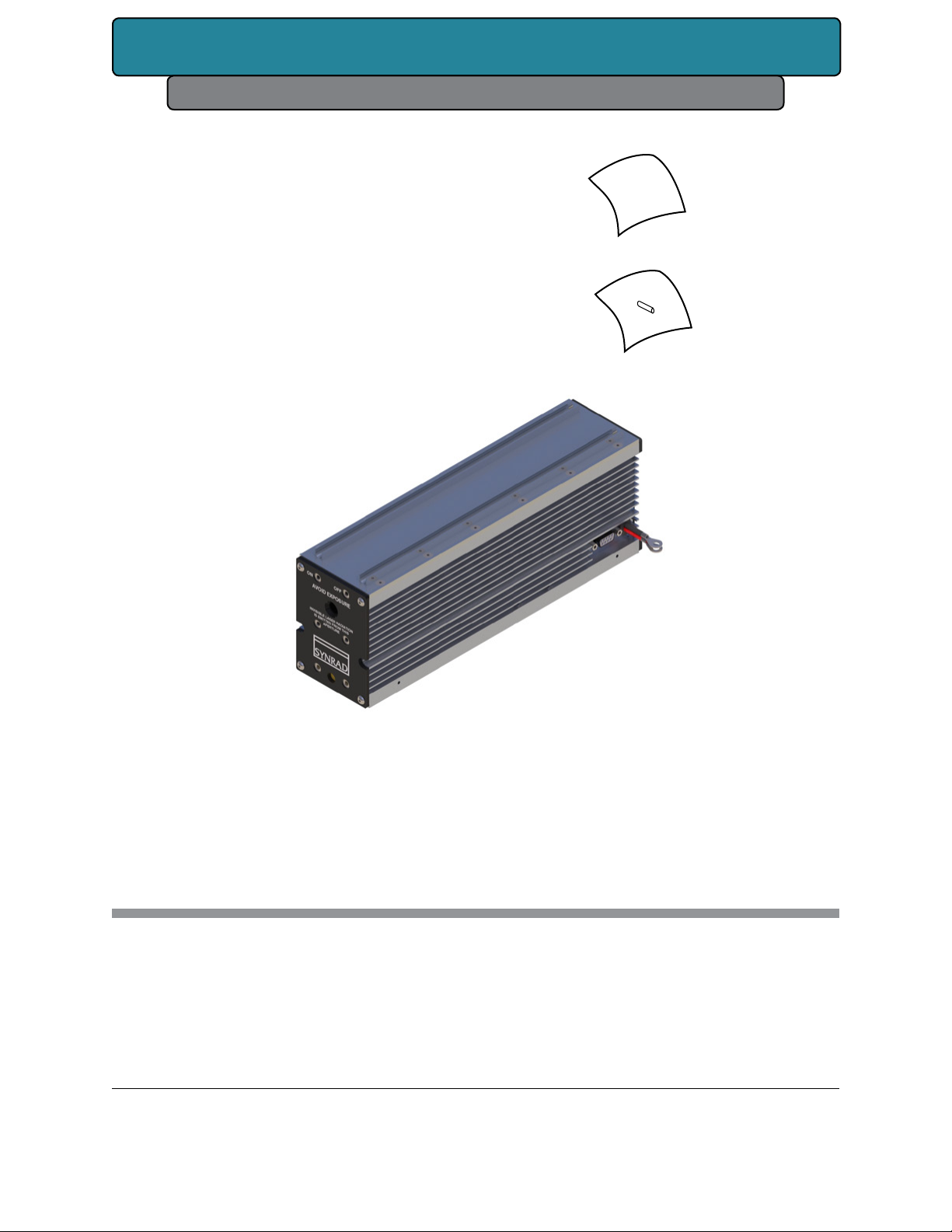
Each item below is also listed in tables that follow:
SYNRAD OEM 32-1 Laser – for cutting, welding, drilling, and marking a wide variety of prod-
ucts and materials.
Customer Communication Flier – Instead of the laser manual CD, please follow the instruc-
tions for our latest laser manual(s) located here: http://synrad.com/synrad/docroot/resources/
libraries/manuals.
Spare Fuse- Fuses protect internal circuitry. A 10 A fuse is included with our 32-1 lasers.
Final Test Report (not shown) – Contains data collected during the laser’s final pre-shipment
test.
SYNRAD® 32-1 Operator’s Manual Version 2.2
10
Page 11
Introduction
Guidelines & Content Description
SYNRAD CO2
®
Web Flier
Spare Fuse(s)
Figure 1-1 32-1 Ship kit contents.
Table 1-1 32-1 ship kit contents.
Shipping Box Contents Qty Shipping Box Contents Qty
32-1 Laser ................................................1 Mounting Bolts ...................................3
Customer flier .......................................1 Final Test Report (not shown) ........1
Spare Fuses ...................(As Required)
SYNRAD® 32-1 Operator’s Manual Version 2.2
11
Page 12

Introduction
Guidelines & Content Description
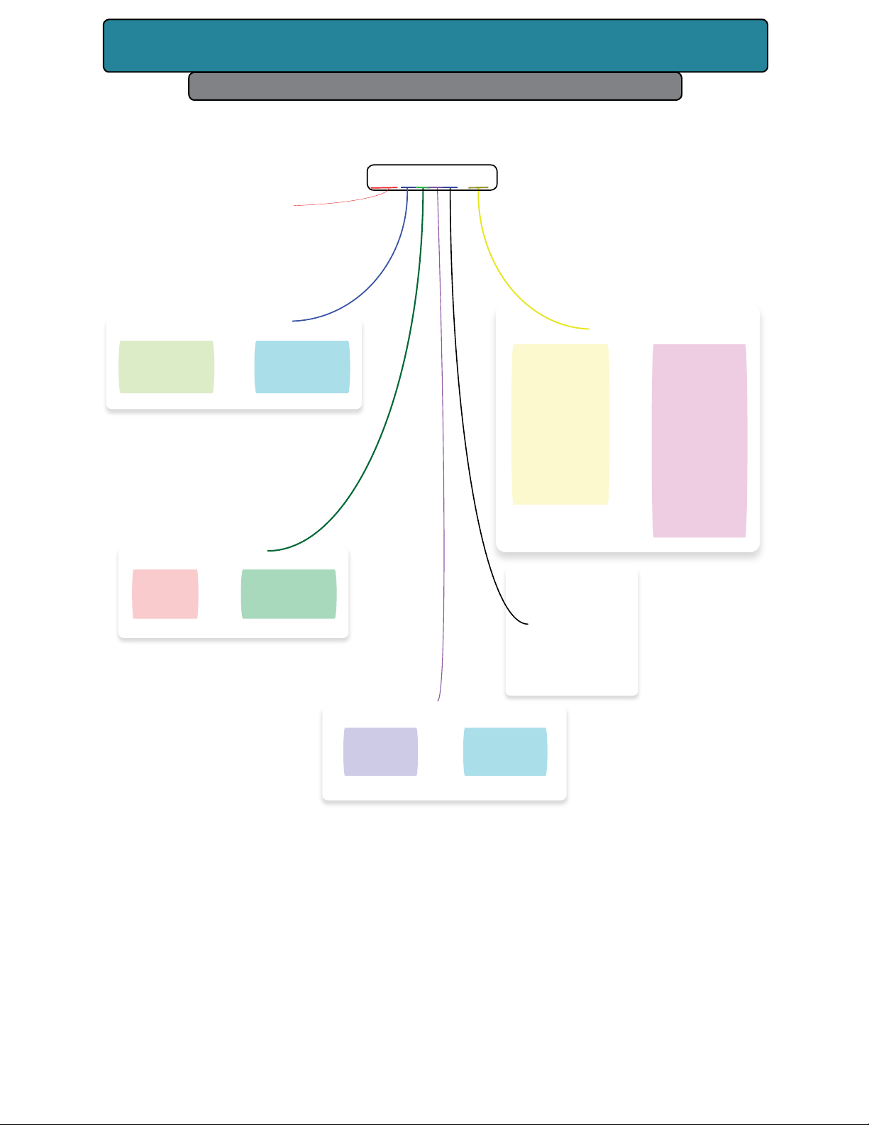
32-1 nomenclature
The 32-1 nomenclature section includes:
Model numbers
32-1 laser versions
The last three characters in the 32-1 model number serve to designate the functional category,
cooling method, and model version. The functional category is indicated by a “S” for Standard
(OEM) models. The next letter indicates the cooling method: “A” for air-cooled lasers (where the
customer must provide the proper cooling via fans or blowers). OEM and Air cooled models
are the only options available for the 32-1. The last letter in the model number indicates the
current model version “C”. For example, the model number 32-1 SAC designates the 32-1 laser
as a Standard OEM, Air-cooled version C.
SYNRAD® 32-1 Operator’s Manual Version 2.2
12
Page 13
Introduction
Features & Nomenclature
32-1 (Laser Family)
32-1SAC-
Power Options (Watt)
1
S
=
Safety Options
=
5
Standard OEM
Cooling Options
Other Options
NIL
9.3
10.2
CL
Other
Model
Version
Number
(A-Z)
=
10.6 µ
9.3 µ
10.2 µ
Closed Loop Kit
Customer
Specic
Options
Figure 1-2 Anatomy of a model number.
A
=
Air
SYNRAD® 32-1 Operator’s Manual Version 2.2
13
Page 14
Laser Safety
2
Laser Safety
yourself with all denitions and their signicance.
unsafe practices that could result in death, severe injury, or product damage.
disposal.
your 32-1 laser.
tion information.
Warning
Hazard Information – includes equipment label terms and hazards, please familiarize
General & Other Hazards – provides important information about the hazards and
Disposal – information on your 32-1 laser parts and/or components as they pertain to
Additional safety Information – describes how to nd additional information about
Compliance – explains in the subsections therein applicable and appropriate regula-
Note:
Serious
personal
injury
Read the entire safety section. This will ensure you are familiar with
the hazards and warnings prior to starting.
Although the 32-1 wavelength is 10.6 microns (µm) any Class 4
laser product that emits invisible infrared laser radiation in the
9.3–10.6 µm CO wavelength band is capable of seriously burning
human tissue.
Because direct or diuse laser radiation can inict severe corneal
injuries, always wear eye protection when in the same area as an
exposed laser beam.
Do not allow the laser beam to contact a person!
This product emits an invisible laser beam that is capable of seriously burning human tissue.
Always be aware of the beam’s path and always use a beam block
while testing.
SYNRAD® 32-1 Operator’s Manual Version 2.2
14
Page 15
Laser Safety
Warning
Serious
personal
injury
For laser systems being used or sold within the U.S.A., customers
should refer to and follow the laser safety precautions described
American National Standards Institute (ANSI) document Z136.12007, Safe Use of Lasers.
For laser systems being used or sold outside the U.S.A., customers should refer to and follow the laser safety precautions
described in European Normative and International Electrotechnical Commission documents IEC/TR 60825-14:2004, Safety of
Laser Products – Part 14: A User’s Guide.
Hazard Information
Hazard information includes terms, symbols, and instructions used in this manual or on the
equipment to alert both operating and service personnel to the recommended precautions in
the care, use, and handling of Class 4 laser equipment.
Terms
Certain terms are used throughout this manual or on the equipment labels. Please familiarize
yourself with their denitions and signicance.
Imminent hazards which, if not avoided, will result in death or serious injury.
Potential hazards which, if not avoided, could result in death or serious injury.
Hazards which, if not avoided, could result in minor or moderate injury.
Caution- potential hazards or unsafe practices which, if not avoided, may result in
product damage.
Important information or recommendations concerning the subject under discussion.
SYNRAD® 32-1 Operator’s Manual Version 2.2
15
Page 16
Laser Safety
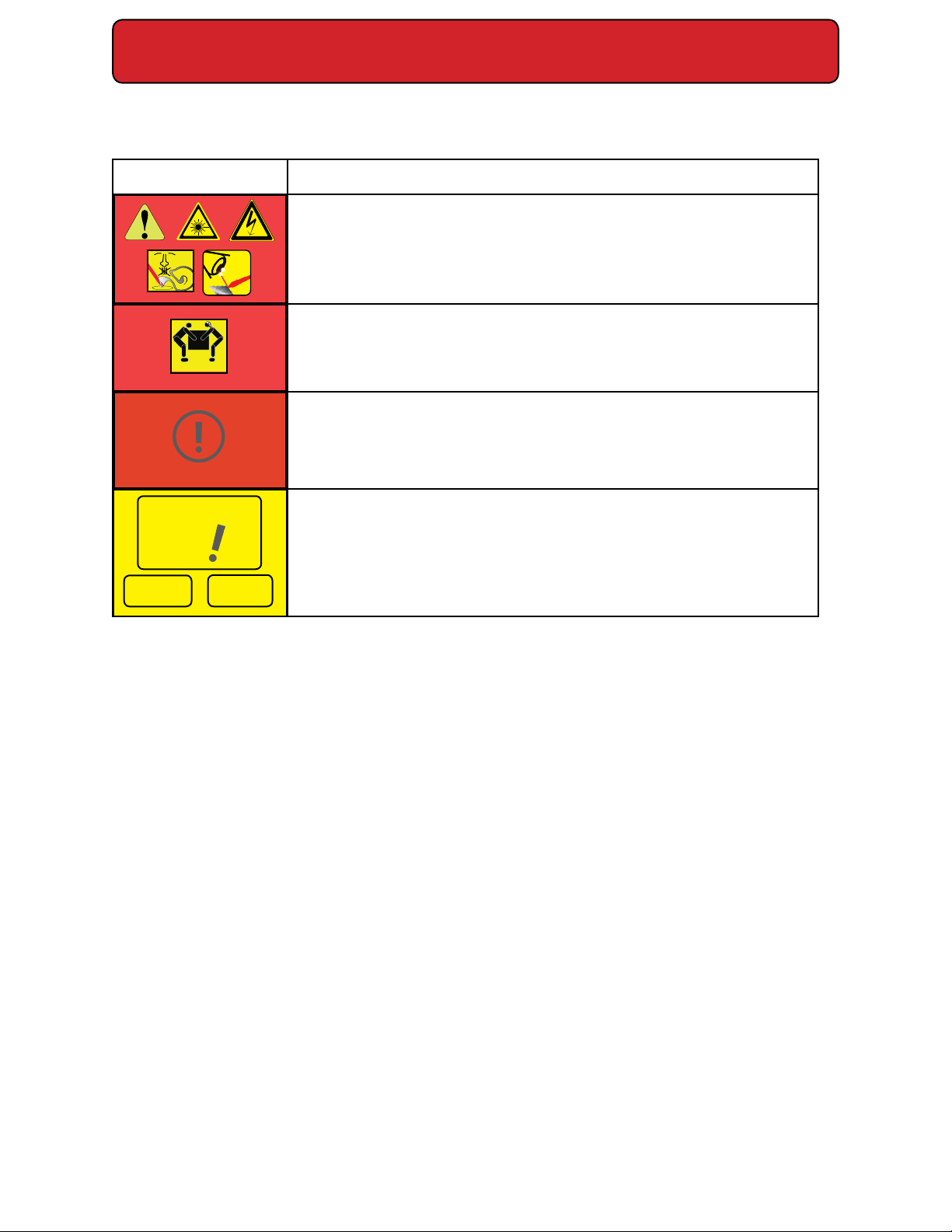
Person Lift
Parameter Description
WARNING: Potential & Imminent hazards which, if not avoided,
could result in death or serious injury.
Alerts operator of serious dangers, hazardous radiation, hazardous
voltages, vapor hazard, & reective dangers.
DANGER: Hazards which, if not avoided, could result in minor or
Two
moderate injury.
Alerts operator of lifting dangers.
CAUTION: Potential hazards or unsafe practices which, if not
avoided, may result in product damage.
Alerts operator of equipment dangers.
Important
Note:
Note:
Tip:
IMPORTANT NOTES & TIPS:
Content specic information and/or recommendations.
Figure 2-1 Warning, danger, caution and content specic information icons and denitions.
SYNRAD® 32-1 Operator’s Manual Version 2.2
16
Page 17
Laser Safety
General Hazards
Following are descriptions of general hazards and unsafe practices that could result in death,
severe injury, or product damage. Specic warnings and cautions not appearing in this section are found throughout the manual.
Warning
Serious
personal
injury
This product is not intended for use in explosive, or potentially explosive, atmospheres.
Materials processing with a laser can generate air contaminants such as vapors, fumes,
and/or particles that may be noxious, toxic, or even fatal.
Material Safety Data Sheets (MSDS) for materials being processed should be thorough-
ly evaluated and the adequacy of provisions for fume extraction, ltering, and venting
should be carefully considered. Review the following references for further information
on exposure criteria:
Review the following references for further information on exposure criteria:
ANSI Z136.1-2007, Safe Use of Lasers, section 7.3.
U.S. Government’s Code of Federal Regulations: 29 CFR 1910,
Subpart Z.
Threshold Limit Values (TLV’s) published by the American Conference of Governmental
Industrial Hygienists (ACGIH).
It may be necessary to consult with local governmental agencies regarding restrictions on
the venting of processing vapors.
The use of aerosol dusters containing diuoroethane causes “blooming”, a condition that
signicantly expands and scatters the laser beam. This beam expansion can eect mode
quality and/or cause laser energy to extend beyond the connes of optical elements in the
system, possibly damaging acrylic safety shielding. Do not use air dusters containing diuoroethane in any area adjacent to CO2 laser systems because diuoroethane persists for long
time periods over wide areas.
Do not allow laser radiation to enter the eye by viewing direct or
reected laser energy. CO laser radiation can be reected from
metallic objects even though the surface is darkened. Direct or
diuse laser radiation can inict severe corneal injuries leading to permanent eye damage or blindness. All personnel must
wear eye protection suitable for 9.3–10.6 µm CO radiation when
in the same area as an exposed laser beam. Eye wear protects
against scattered energy but is not intended to protect against
direct viewing of the beam—never look directly into the laser
output aperture or view scattered laser reections from metallic
surfaces.
Enclose the beam path whenever possible. Exposure to direct or
diuse CO laser radiation can seriously burn human or animal
tissue, which may cause permanent damage.
SYNRAD® 32-1 Operator’s Manual Version 2.2
17
Page 18
Laser Safety
Light
Warning!
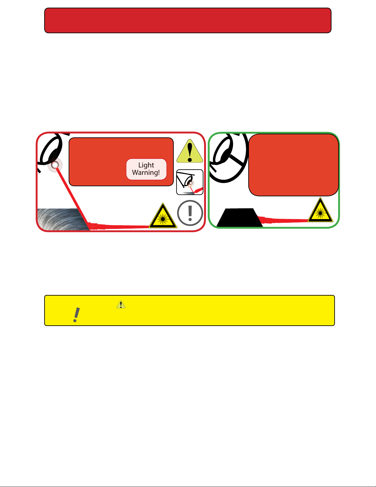
32-1 lasers should be installed and operated in manufacturing or laboratory facilities by
trained personnel only. Due to the considerable risks and hazards associated with the installation and operational use of any equipment incorporating a laser, the operator must follow
product warning labels and instructions to the user regarding laser safety. To prevent exposure to direct or scattered laser radiation, follow all safety precautions specied throughout
this manual and exercise safe operating practices per ANSI Z136.1-2007, Safe Use of Lasers at
all times when actively lasing.
Due to the specic properties of laser light, a unique set of safety hazards that dier from other light sources must be considered. Just like light, lasers can be reected, refracted, diracted
or scattered.
Warning
Serious
personal
injury
Figure 2-2 Always wear safety glasses or protective goggles with side shields to reduce the
risk of damage to the eyes when operating the laser.
A CO2 laser is an intense energy source and will ignite most materials under the proper conditions. Never operate the laser in the presence of ammable or explosive materials, gases,
liquids, or vapors.
Important
Note:
“Caution - The use of controls or adjustments or performance of procedures
other than those specied herein may result in hazardous radiation exposure.”
Never use organic material or metals as a beam
blocker. There are very
few exceptions, e.g. black
anodized metal such as
aluminum because this is
non reective surface.
The use of controls or adjustments or performance of procedures other than those specied
herein may result in exposure to hazardous invisible laser radiation, damage to, or malfunction of the laser. Severe burns will result from exposure to the laser beam.
Safe operation of the laser requires the use of an external beam block to safely block the
beam from traveling beyond the desired work area. Do not place your body or any combustible object in the path of the laser beam. Use a water-cooled beam dump or power meter, or
similar non-scattering, noncombustible material as the beam block. Never use organic material or metals as the beam blocker; organic materials, in general, are apt to combust or melt and
metals act as specular reectors which may create a serious hazard outside the immediate
work area.
Always wear safety glasses or protective goggles with side shields to reduce the risk of damage to the eyes when operating the laser.
SYNRAD® 32-1 Operator’s Manual Version 2.2
18
Page 19

Laser Safety
Disposal
This product contains components that are considered hazardous industrial waste. If a sit-
uation occurs where the laser is rendered non-functional and cannot be repaired, it may be returned to SYNRAD® who, for a fee, will ensure adequate disassembly, recycling and/or disposal of the product.
Other hazards
The following hazards are typical for this product family when incorporated for intended use:
(A) risk of injury when lifting or moving the unit; (B) risk of exposure to hazardous laser energy
through unauthorized removal of access panels, doors, or protective barriers; (C) risk of exposure to hazardous laser energy and injury due to failure of personnel to use proper eye protection and/or failure to adhere to applicable laser safety procedures; (D) risk of exposure to
hazardous or lethal voltages through unauthorized removal of covers, doors, or access panels;
(E) generation of hazardous air contaminants that may be noxious, toxic, or even fatal.
Additional laser safety information
The SYNRAD web site (http://www.synrad.com/LaserFacts/safetyinfo.html) contains an online
laser safety handbook that provides information on (1) Laser Safety Standards for OEM’s/System Integrators, (2) Laser Safety Standards for End Users, (3) References and Sources, and (4)
Assistance with Requirements.
In addition, the Occupational Safety and Health Administration (OSHA) provides an online
Technical Manual (located at http://www.osha.gov/dts/osta/otm/otm_iii/otm_iii_6.html). Section III, Chapter 6 and Appendix III are good resources for laser safety information.
Another excellent laser safety resource is the Laser Institute of America (LIA). Their comprehensive web site is located at http://www.lia.org.
SYNRAD® 32-1 Operator’s Manual Version 2.2
19
Page 20
Laser Safety
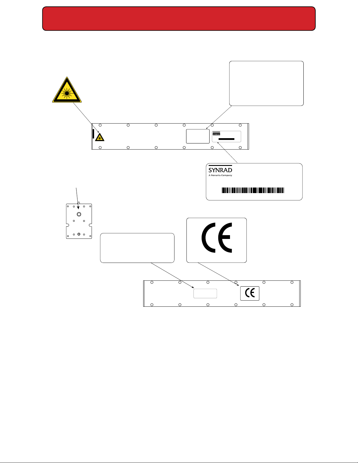
32-1 label locations
AVOID EXPOSURE
INVISIBLE LASER RADIATION
IS EMITTED FROM THIS
APERTURE
TOP VIEW
CAUTION
These RF Excited Lasers must be provided with a
pre-ionizing "Tickle" signal during standby or
laser "low" periods. This is automatically provided
with Synrad's UC Series power controller. This signal
keeps the plasma ionized during laser "low" periods
and facilitates breakdown and pulse to pulse fidelity.
Damage or malfunction may occur if this or
equivalent drive signals are not used. See manual
for tickle pulse specifications or contact factory.
CAUTION
with Synrad's UC Series power controller. This signal
keeps the plasma ionized during laser "low" periods
and facilitates breakdown and pulse to pulse fidelity.
MODEL #: 32-1SAC
SERIAL #: 0481263115066
TESTED AT
30 Volts MFG September 20, 2011
Complies with IEC 60825-1 (2007) and 21 CFR 1040.10 except
for deviations pursuant to Laser Notice No. 50 dated June 24, 2007.
SYNRAD, Inc. 4600 Campus Place, Mukilteo WA 98275 425.349.3500
These RF Excited Lasers must be provided with a
pre-ionizing "Tickle" signal during standby or
laser "low" periods. This is automatically provided
Damage or malfunction may occur if this or
equivalent drive signals are not used. See manual
for tickle pulse specifications or contact factory.
OEM version
MODEL #: MODELNUMBER
SERIAL #: SERIALNUMBER
MFG October 25, 2018
This laser component does not comply with standards for complete laser products as
TESTED AT 48 Volts
Specified by 21 CFR 1040.10 or IEC 60825-1
.
AVOID EXPOSURE
INVISIBLE LASER RADIATION
IS EMITTED FROM THIS
APERTURE
FRONT VIEW
This laser product is manufactured under
one or more of the following U.S. Patents:
6,195,379 6,198,758 6,198,759 6,603,794
6,614,826 7,480,323 9,031,110 9,197,028
Other U.S. and International Patents pending.
4600 Campus Place, Mukilteo WA 98275 | 425.349.3500
MADE IN THE U.S.A.
This laser product is manufactured under
one or more of the following U.S. Patents:
5,602,865 6,195,379 6,198,758 6,198,759
6,603,794 6,614,826 7,480,323
Other U.S. and International Patents pending.
BOTTOM VIEW
MADE IN THE U.S.A.
Figure 2-3 38-1 Hazard label locations.
SYNRAD® 32-1 Operator’s Manual Version 2.2
20
Page 21

Laser Safety
Compliance
Center for Devices and Radiological Health (CDRH) requirements.
Federal Communications Commission (FCC) requirements.
European Union (EU) requirements.
SYNRAD® lasers are designed, tested, and certied to comply with certain United States (U.S.)
and European Union (EU) regulations. These regulations impose product performance requirements related to electromagnetic compatibility (EMC) and product safety characteristics
for industrial, scientic, and medical (ISM) equipment. The specic provisions to which systems containing 32-1 lasers must comply are identied and described in the following paragraphs.
In the U.S., laser safety requirements are governed by the Center for Devices and Radiological
Health (CDRH) under the auspices of the U.S. Food and Drug Administration (FDA) while radiated emission standards fall under the jurisdiction of the U.S. Federal Communications Commission (FCC). Outside the U.S., laser safety and emissions are governed by European Union
(EU) Directives and Standards.
In the matter of CE-compliant laser products, SYNRAD assumes no responsibility for the
compliance of the system into which the product is integrated, other than to supply and/or
recommend laser components that are CE marked for compliance with applicable European
Union Directives.
Because OEM laser products are intended for incorporation as components in a laser processing system, they do not meet all of the Standards for complete laser processing systems
as specied by 21 CFR, Part 1040 or EN 60825-1. SYNRAD assumes no responsibility for the
compliance of the system into which OEM laser products are integrated.
Center for Devices and Radiological
Health (CDRH) requirements
Product features incorporated into the design of 32-1 lasers to comply with CDRH requirements are integrated as panel controls or indicators, internal circuit elements, or input/output
signal interfaces. Specically, these features include a lase and laser ready indicators, remote
interlock for power on/o, a laser aperture shutter switch, and a ve-second delay between
power on and lasing. Incorporation of certain features is dependent on the laser version (Keyswitch or OEM). See the Class 4 safety features, located in the following table, that indicate
which features are available on 32-1 lasers, the type and description of the feature, and if the
feature is required by CDRH regulations.
OEM models
32-1 OEM lasers are OEM products intended for incorporation as components in laser process-
ing systems. As supplied by SYNRAD, these lasers do not meet the requirements of 21 CFR,
Subchapter J without additional safeguards. In the U.S., the Buyer of these OEM laser
SYNRAD® 32-1 Operator’s Manual Version 2.2
21
Page 22

Laser Safety
components is solely responsible for the assurance that the laser processing system sold to
an end user complies with all laser safety requirements before the actual sale of the system.
Under CDRH regulations, the Buyer must submit a report to the CDRH prior to shipping the
system. In jurisdictions outside the U.S., it is the sole responsibility of the Buyer of these OEM
(FCC) requirements
The United States Communication Act of 1934 vested the Federal Communications Commission (FCC) with the authority to regulate equipment that emits electromagnetic radiation in
the radio frequency spectrum. The purpose of the Communication Act is to prevent harmful
electromagnetic interference (EMI) from aecting authorized radio communication services.
The FCC regulations that govern industrial, scientic, and medical (ISM) equipment are fully
described in 47 CFR, Part 18, Subpart C.
SYNRAD® 32-1 lasers have been tested and found to comply by demonstrating performance
characteristics that have met or exceeded the requirements of 47 CFR, Part 18, Radiated and
Conducted Emissions.
FCC information to the user
The following FCC information to the user is provided to comply with the requirements
Note
of 47 CFR, Part 18, Section 213.
Interference Potential
In our testing, SYNRAD has not discovered any signicant electrical interference traceable to
32-1 lasers.
System Maintenance
Ensure that all exterior covers are properly fastened in position.
Measures to Correct Interference
If you suspect that your laser interferes with other equipment, take the following steps to
minimize this interference:
1
Use shielded cables to and from the equipment that is experiencing interference prob-
lems.
2
equipment or system it is connected to.
FCC caution to the user
The Federal Communications Commission warns the user that changes or modications of
the unit not expressly approved by the party responsible for compliance could void the user’s
authority to operate the equipment.
Ensure that the laser is properly grounded to the same electrical potential as the
SYNRAD® 32-1 Operator’s Manual Version 2.2
22
Page 23

Laser Safety
European Union (EU) requirements
RoHS compliance
SYNRAD® 32-1 lasers meet the requirements of the European Parliament and Council Directive
2011/65/EU on the Restriction of the Use of Certain Hazardous Substances in Electrical and
Electronic Equipment that establishes maximum concentration values for certain hazardous
substances in electrical and electronic equipment.
Laser safety standards
Under the Low Voltage Directive, 2006/95/EC, the European Norm (EN) document EN 60825-
1:2007 was developed to provide laser safety guidance and includes clauses on Engineering
Specications, Labeling, Other Informational Requirements, Additional Requirements for
Specic Laser Products, Classication, and Determination of the Accessible Emission Level. To
develop a risk assessment plan/laser safety program for users, see IEC/TR 60825-14:2004 that
includes clauses on Administrative Policies, Laser Radiation Hazards, Determining the MPE, Associated Hazards, Evaluating Risk, Control Measures, Maintenance of Safe Operation, Incident
Reporting and Accident Investigation, and Medical Surveillance.
OEM models
32-1 OEM lasers are OEM products intended for incorporation as components in laser
processing systems. As supplied by SYNRAD, these lasers do not meet the requirements
of EN 60825-1:2014 without additional safeguards. European Union Directives state that
“OEM laser products which are sold to other manufacturers for use as components of any
system for subsequent sale are not subject to this Standard, since the nal product will
itself be subject to the Standard.” This means that Buyers of OEM laser components are
solely responsible for the assurance that the laser processing system sold to an end-user complies with all laser safety requirements before the actual sale of the system. Note
that when an OEM laser component is incorporated into another device or system, the
entire machinery installation may be required to conform to EN 60825-1 :2014; EN 602041:2006, Safety of Machinery; the Machinery Directive, EN 2006/42/EC; and/or any other
applicable Standards and in cases where the system is being imported into the U.S., it
must also comply with CDRH regulations.
In cases where the Buyer is also the end-user of the OEM laser product, the Buyer/end-user must integrate the laser so that it complies with all applicable laser safety standards as
set forth above. The following table shows the Class 4 safety features, summarizes 32-1
product features, indicating the type and description of features and whether those features are required by European Union regulations.
Electromagnetic interference standards
The European Union’s Electromagnetic Compatibility (EMC) Directive, 2004/108/EC, is the sole
Directive developed to address electromagnetic interference (EMI) issues in electronic equipment. In particular, the Directive calls out European Norm (EN) documents that dene the
emission and immunity standards for specic product categories. For 32-1 lasers, EN 610006-4 denes radiated and conducted RF emission limits while EN 61000-6-2 denes immunity
requirements for industrial environments.
SYNRAD® 32-1 Operator’s Manual Version 2.2
23
Page 24

Laser Safety
Table 2-1 Class 4 safety features as required by CDRH and EN.
Required by: Available on:
Feature Location / Description CDRH EN60825-1 OEM 32-1
Keyswitch Rear panel control Yes Yes No
On/O/Reset Keyswitch controls power to laser electronics. Key cannot be removed
from switch in the “On” position.
Shutter Laser control Yes Yes No
function Functions as a beam attenuator to disable RF driver/laser output when closed.
Shutter Rear panel indicator (Blue) No No No
indicator Illuminates blue to indicate shutter is open.
Ready Rear panel indicator (Yellow) Yes Yes No
indicator2 Indicates that laser has power applied and is capable of lasing.
Lase Rear panel indicator (Red) No No No
indicator Indicates that is actively lasing. Lase LED illuminates when the duty cycle of the Com-
mand signal is long enough to produce laser output.
Power fail circuit element Yes Yes No
lockout1 Disables RF driver/laser output if input power is removed then later reapplied (AC
power failure or remote interlock actuation) while Keyswitch is in “On” position.
Remote Side panel connection Yes Yes Yes
Interlock Disables RF driver/laser output when a remote interlock switch on an equipment door
or panel is opened.
Remote Side panel indicator (Green/Red) No No No
Interlock Illuminates green when Remote Interlock circuitry is closed indicator Illuminates red
when interlock circuitry is open.
Over circuit element No No Yes
temperature Temperature shutdown occurs if temperature of the laser protection tube rises above
safe operating limits.
Temp Side panel indicator (Green/Red) No No No
indicator Illuminates green when laser temperature is within operating limits, changing to red
when thermal limits are exceeded.
Warning 32-1 exterior Yes Yes Yes
labels Labels attached to various external housing locations to warn personnel of potential
laser hazards.
1 On OEM versions, the Power indicator illuminates and the ve (5) second delay begins when DC power is ap-
plied to the laser.
SYNRAD® 32-1 Operator’s Manual Version 2.2
24
Page 25

Laser Safety
SYNRAD® 32-1 lasers have demonstrated performance characteristics that have met or exceeded the requirements of EMC Directive 2014/30/EU.
When integrating SYNRAD 32-1 OEM lasers, the Buyer and/or integrator of the end system is
responsible for meeting all applicable Standards to obtain the CE mark. To aid this compliance
process, SYNRAD testing program has demonstrated that 32-1 lasers comply with the relevant
requirements of 2014/30/EU, the Electromagnetic Compatibility Directive, as summarized in
the table below.
Table 2-2 European Union Directives.
Applicable Standards / Norms
2014/30/EU Electromagnetic Compatibility Directive
2014/35/EU Low Voltage Directive
2011/65/EU RoHS Directive
EN 61010-1:2010 Safety Requirements for Electrical Equipment for Measure-
ment, Control, and Laboratory Use - Part 1: General
Requirements
EN 61000-6-4:2007 Radiated Emissions Group 1, Class A
EN 61000-6-4:2007 Conducted Emissions Group 1, Class A
EN 61000-6-2:2005 Electrostatic Discharge Immunity
EN 61000-6-2:2005 RF Electromagnetic Field Immunity
EN 61000-6-2:2005 Electrical Fast Transient/Burst Immunity
EN 61000-6-2:2005 Conducted RF Disturbances Immunity
After a laser or laser processing system has met the requirements of all applicable EU Directives, the product can bear the ocial compliance mark of the European Union as a Declaration of Conformity.
After a laser or laser processing system has met the requirements of all applicable EU Directives, the product can bear the ocial compliance mark of the European Union as shown in
the gure below and a Declaration of Conformity is provided for the compliant component.
Figure 2-4 European compliance mark.
SYNRAD® 32-1 Operator’s Manual Version 2.2
25
Page 26

Laser Safety
Declaration of Conformity
in accordance with ISO / IEC 17050-2:2004
We,
Manufacturer’s Name: SYNRAD® A ©Novanta Company
Manufacturer’s Address: 4600 Campus Place
Mukilteo, WA 98275 U.S.A.
Hereby declare under our sole responsibility that the following equipment:
Product Name: 32-1 Laser
Model Number: 32-1SAC (*OEM)
Conforms to the following Directive(s) and Standard(s):
Applicable Directive(s): 2014/30/EU Electromagnetic Compatibility Directive
2014/35/EU Low Voltage Directive
2011/65/EU RoHS Directive
Applicable Standard(s):
EN 61010-1:2010 Safety Requirements for Electrical Equipment for Measurement, Control, and
Laboratory Use - Part 1: General Requirements
EN 61000-6-4:2007 Radiated Emissions, Group 1, Class A
EN 61000-6-4:2007 Conducted Emissions, Group 1, Class A
EN 61000-6-2:2005 Electrostatic Discharge Immunity
EN 61000-6-2:2005 RF Electronic Fields Immunity
EN 61000-6-2:2005 Electrical Fast Transient/Burst Immunity
EN 61000-6-2:2005 Conducted RF Disturbances Immunity
*OEM lasers do not comply with EN 60825-1:2014, Safety of Laser Products. Buyers of OEM laser products are solely
responsible for meeting applicable Directives and Standards for CE compliance and marking.
Corporate Ocer: European Contact:
IN PROGRESS
Mel Lima, Sr. Quality and Reliability Director of SYNRAD
Dated:
Novanta Distribution (USD) GmbH
Parkring 57-59
85748 Garching bei München, Germany
Figure 2-5 32-1 Declaration Document.
SYNRAD® 32-1 Operator’s Manual Version 2.2
26
MADE IN THE U.S.A.
900-20976-23 Rev B
Page 27
Operation
3
Use information in this chapter to familiarize yourself with 32-1 controls and indicators. Reference the Quick Start Guide for the initial startup process.
This chapter contains the following information:
Controls and indicators – displays and describes exterior controls and indicators on 32-1
OEM lasers.
Initial start-up – Reference the Technical Reference chapter in this operation manual.
Caution
Possible
Equipment
Damage
Remove the aperture seal before ring the laser. The self-adhesive seal is installed to prevent dust from entering the laser housing during shipment and installation and must be removed before
operation. During laser operation, use a gas purge to keep dust and
vapor out of the beam path.
Applying PWM Command pulses directly to the laser without rst
sending tickle pulses for at least two seconds will cause unpredictable laser emission, degrade optical rise time, and may lead to RF
Driver failure.
SYNRAD® 32-1 Operator’s Manual Version 2.2
27
Page 28
Operation
Controls & Indicators
Aperture Seal
Exit Aperture
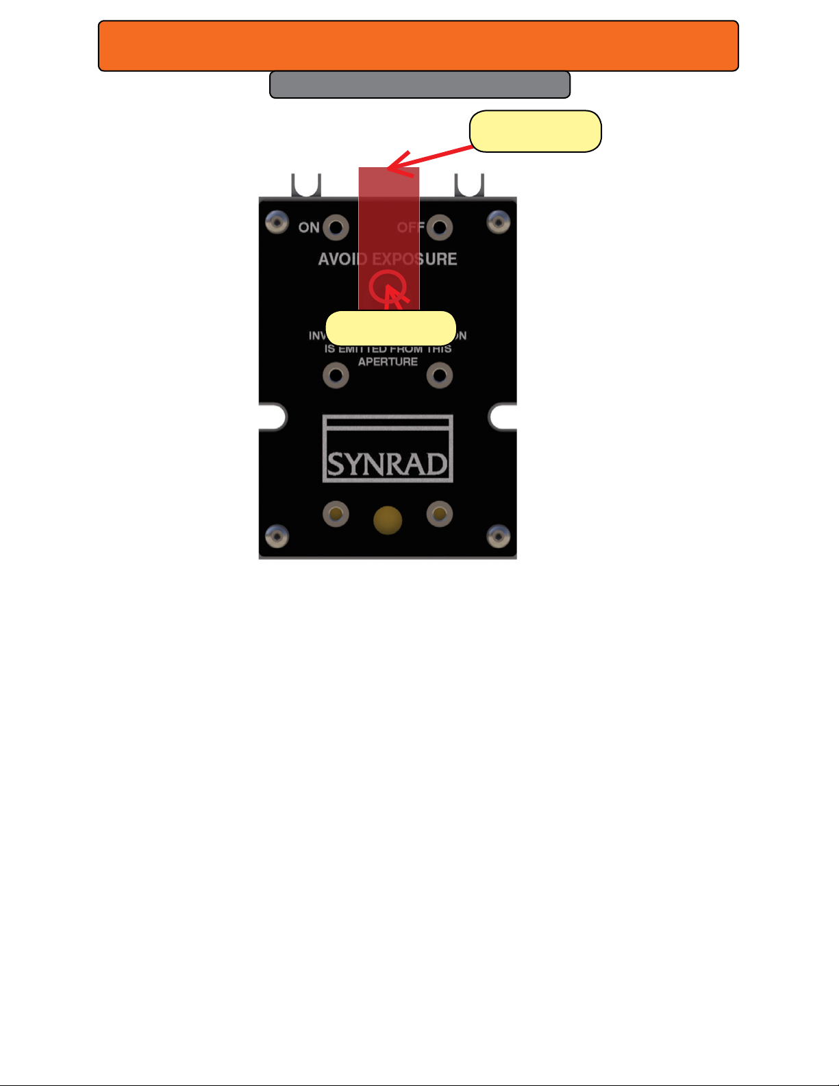
Figure 3-1 Front panel controls and indicators.
Controls and Indicators
32-1 front panel
Aperture Seal – prevents dust from damaging the output coupler during shipping. Remove
the red self-adhesive label before applying power to the laser.
Laser Exit Aperture – provides an opening from which the beam is emitted when lasing.
32-1 rear panel
The back panel is just a black plate.
SYNRAD® 32-1 Operator’s Manual Version 2.2
28
Page 29
Operation
Controls & Indicators
DB9 Connector
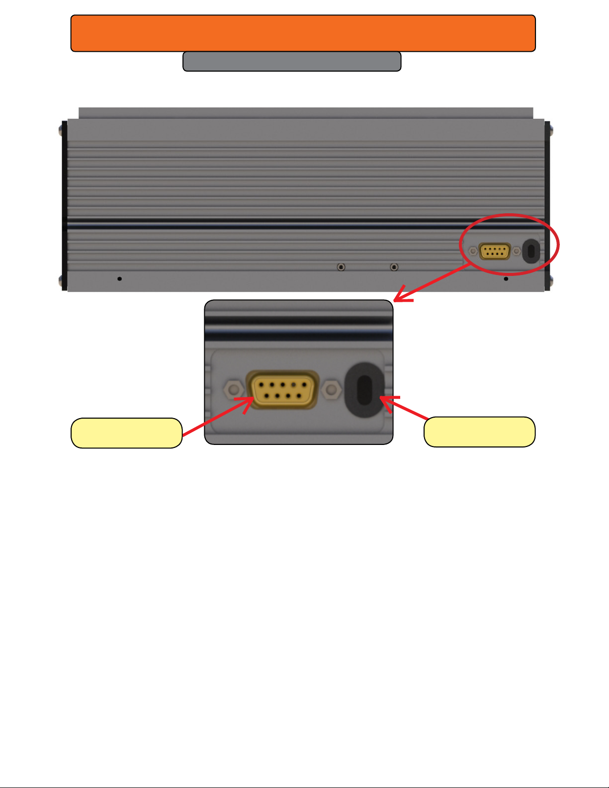
Figure 3-2 Side panel controls and indicators.
DC Power Cables
Side panel
DC Power Cables – red (+) and black (–) DC Power input cables are manufactured from #12
AWG wire and measure 1.1 meters (3.5 feet) in length.
DB-9 Connector – provides an interconnection for message, fault shutdown, remote interlock,
remote keyswitch, and interface signals. Refer to the DB-9 connections section in the Technical Reference chapter for information on pin assignments and function.
SYNRAD® 32-1 Operator’s Manual Version 2.2
29
Page 30
Technical Reference
4
Technical reference summary
Technical overview – briey describes 32-1 technology, design RF power supply
and basic optical setup.
Control circuitry & cooling – introduces various aspects of the 32-1 control signals &
cooling.
DB-9 connections – describes input/output signals and specications for the side
mounted DB-9 connector.
DC power – provides information about DC power.
Integrating 32-1 safety features – describes how to integrate 32-1 safety features into
your automated control system.
32-1 general specications – provides specications for the 32-1 laser.
Model 32-1 package outline drawing – illustrates laser package and mounting dimen-
sions for OEM 32-1.
32-1 packaging instructions – describes how to package 32-1 lasers for shipment.
Caution
Possible
Equipment
Damage
Small amounts of contaminants on the laser’s output window (or on
any optic in the beam path) can absorb enough energy to damage
the optic. Inspect all beam delivery optics periodically for signs of
contaminants and carefully clean as required.
In dirty environments, purge laser optics using ltered air or nitrogen
to prevent vapor and debris from accumulating on optical surfaces.
SYNRAD® 32-1 Operator’s Manual Version 2.2
30
Page 31

Technical Reference
Technical overview
Introduction
Plasma section
Optical resonator
Control circuitry
Optical setup,
Faults, cooling, and DuoLase®
Introduction
32-1 lasers incorporate the latest technology in sealed carbon dioxide devices, combining the
best features of both waveguide and free space CO laser technology. The all-metal laser tube
construction features the ruggedness, stable optical support, and small size of waveguide
lasers. Low cost is achieved by using simple extruded and welded aluminum structures packaged together with compact, state-of-the-art RF power supplies.
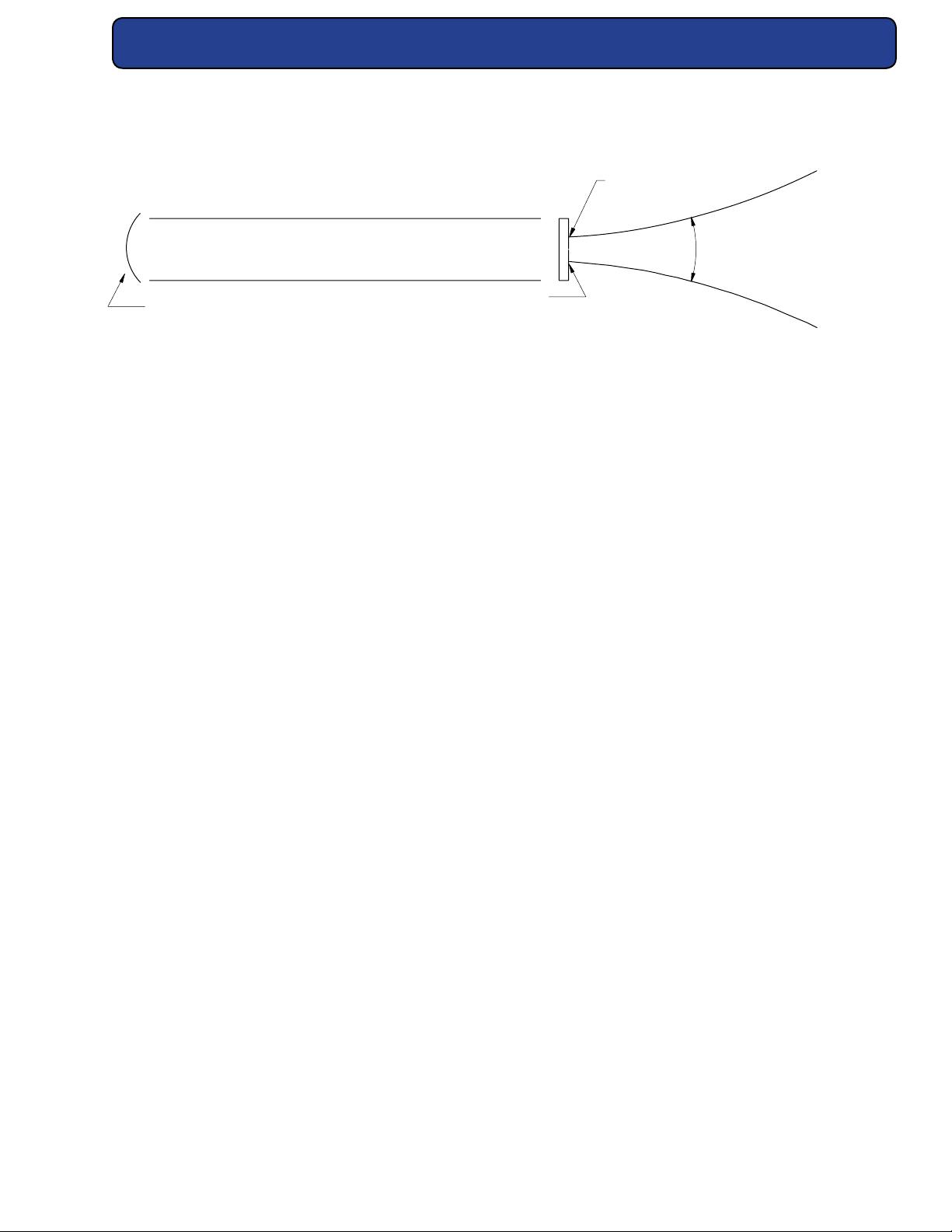
32-1 lasers emit a laser beam with a wavelength of 10.6 microns (µm). The laser beam diverges
due to diraction at a full angle of 8 mrad (milliradians), with the beam waist at the output
aperture of the laser.
Power control of the laser beam is achieved by pulse width modulation (PWM) of the RF drive
circuit. Modulation control can be used to gate the laser on and o at time intervals synchronized with automated processing equipment. It can also be used to control instantaneous
power by adjusting the pulse width (PWM duty cycle) at a variable modulation frequency.
Both methods can be used simultaneously.
Plasma section
The laser consists of an RF-excited plasma tube with an adjustable mirror on each end,
mounted together with the RF drive assembly in a single aluminum chassis. The plasma tube
is made of two-inch square cross-section extruded aluminum tubing with pre-machined
ends welded on. RF drive power is applied between the two electrodes. The internal resonant
circuit induces RF drive on the upper electrode that is 180 degrees out of phase with that of
the lower electrode. Thus the voltage between the two RF electrodes is roughly twice that on
either electrode. Waste heat is conducted away to the outer walls of the laser tube, where it is
transferred to the chassis.
Optical resonator
The optical resonator consists of a curved total reector and a at Zinc Selenide (ZnSe) output
coupler. The mirrors are held on with Viton (uorocarbon) elastomeric o-rings for factory adjustment by means of three screws that are secured by adhesive after alignment. The ceramic
bore in conjunction with the mirror curvatures selected favors a Gaussian (TEM00) mode.
SYNRAD® 32-1 Operator’s Manual Version 2.2
31
Page 32
Technical Reference
DIVERGENCE ≤ 8.0 mrad
TOTAL REFLECTOR
BEAM WAIST DIA. 2.3 ± 0.5 mm
RF DISCHARGE REGION
OUTPUT COUPLER
FULL ANGLE
Ø
Figure 4-1 Beam characteristics.
Controlling Circuitry
Electrical description
Control of laser operation and power output levels is essentially performed using a single PCB.
The Control PCB connects the modulated signal to the RF amplier. It also provides electronics to monitor performance of RF control, output circuitry, input power, temperature, PWM
accuracy, provides outputs to an externally accessible connector, and incorporates reverse
polarity protection.
Model 32-1 lasers use a single RF electrode requiring a single modulated RF drive input from
the Control PCB.
The modulated input PWM signal is generated externally to the laser and connected to the
input connector. This signal is connected to an optoisolator, the output of which is applied
to the PWM switch control circuit. The PWM switch control circuit gates the PWM switch o
and on at the frequency and duty cycle controlled by the modulation source. When the PWM
switch closes, a potential of +30 VDC is applied to the RF Driver. The PWM control circuit provides on/o gating of the PWM switch unless disabled by the ve-second delay, or the fault
shutdown circuits.
The ve-second delay disables PWM output to the RF amplier for a period of approximately
ve seconds after the Remote Keyswitch link is closed (power ON). Note that the supplied
DB-9 jumper plug can be removed to allow the user to insert a remotely located relay or
switch in series with the Remote Keyswitch.
Over temperature fault shutdown occurs when laser tube temperature reaches 60 °C ±2 °C.
Control board operation begins when the supply voltage rises above +18 VDC and remains
below +36 VDC. After start-up, the control board will shut the laser down if supply voltage
falls below +15 VDC or rises above +36 VDC.
SYNRAD® 32-1 Operator’s Manual Version 2.2
32
Page 33
Technical Reference
If an electronics failure causes the control board to output PWM power to the RF Drivers in
excess of 20% of the PWM input, a fault shutdown will occur.
To reset after any fault shutdown, correct the problem(s) then cycle the power on/o to the
laser for 30-seconds. During any fault shutdown, the fault shutdown output (Pin 1 of the DB-9
connector) will latch to low state until a reset occurs.
Power-On Reset is defeated on all OEM versions. OEM customers must provide this required
safety feature elsewhere as part of their equipment integration.
Cooling
32-1 electronics are mounted opposite the laser tube in the smaller section of the “H” bay and
share the same cooling removal as the plasma tube. Typical eciency of CO2 laser plasma
tubes operating in a TEM00 mode is 10% to 12% (radiation out to RF power in). Factor in the
conversion eciency of AC input to RF output and the overall “wall plug” eciency of these
lasers drops to about 6% to 8%, resulting in a considerable amount of heat removal, even at 5
W output power levels; therefore, external cooling in the form of forced air is required.
Caution
Possible
Equipment
Damage
Since 32-1 lasers are OEM products, they do not include cooling
fans. Customers must provide some type of air cooling to prevent
the laser from overheating. See the cooling requirements at the
end of this chapter and cooling 101 located on our website.
Optical setup
After selecting a CO laser for your processing system, the two most important elements to
consider are: (1) delivery optics to transmit the beam to the work area; and (2) focusing optics
to focus the beam onto the part or material to be processed. Each element is crucial in the
development of a reliable laser-based material processing system and each element should
be approached with same careful attention to detail.
SYNRAD® 32-1 Operator’s Manual Version 2.2
33
Page 34
Technical Reference
Delivery optics
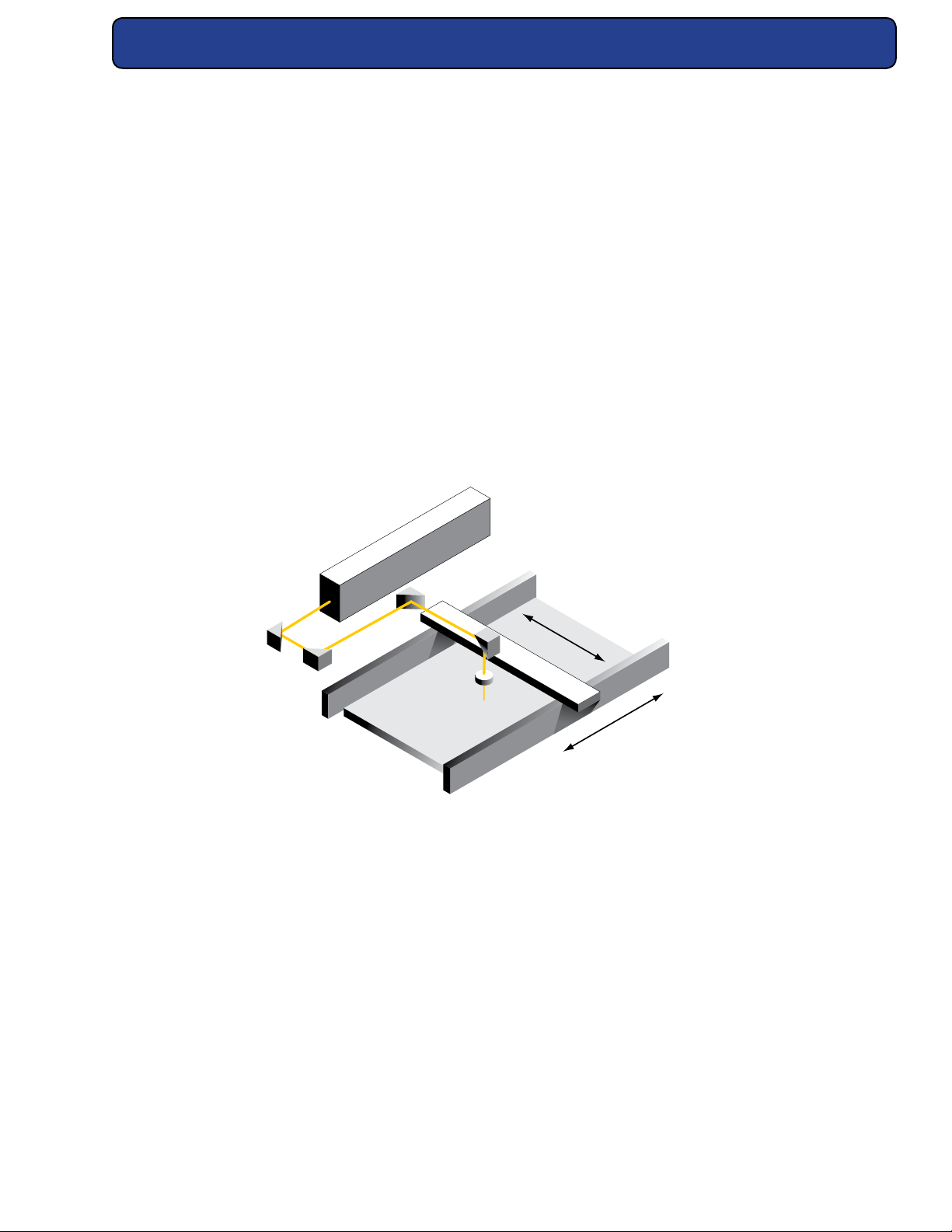
Divergence, or expansion, of the laser beam is important for materials processing since a larger beam entering the focusing optic produces a smaller focused spot. Because the laser beam
diverges slowly, increasing 8 mm in diameter over every meter, 32-1 lasers should be mounted a distance of 1.0–1.5 m (40–60 in) away from the work area. Right angle turning mirrors
are often used in conjunction with the laser mounting position to obtain this distance. Figure
below shows how right angle turning mirrors in a “ying optics” setup create this longer beam
path.
Expander/collimators are optical devices that reduce beam divergence while at the same time
increasing beam diameter by a selectable magnication factor. Adding an expander/collimator to the “ying optics” setup shown below would substantially reduce beam divergence and
any variance in beam diameter caused by the changing optical path length. In xed-length
delivery systems where the laser is positioned only one meter away from the focusing optic
and a small spot size is required, an expander/collimator is again the best solution to provide
the required beam expansion before reaching the focusing optic.
Figure 4-2 “Flying optics” beam path.
Focusing optics
When selecting a focusing optic, the primary consideration should be material thickness and
any vertical tolerances that occur during nal part positioning rather than making a selection
based only on minimum spot size. The chosen focal length should create the smallest possible
focused spot while providing the depth of eld required for the material to be processed. Optics are fragile and must be handled carefully, preferably by the mounting ring only. Be careful
to select optics that are thick enough to withstand the maximum assist gas pressure available
for the process. This is especially important in metal cutting applications using high-pressure
assist gases.
SYNRAD® 32-1 Operator’s Manual Version 2.2
34
Page 35

Technical Reference
Cleanliness is another important issue aecting performance and becomes increasingly important as laser power increases. Dirty or scratched lenses will under perform, exhibit a vastly
shortened lifetime, and may fail catastrophically.
When the application requires air (instead of nitrogen) as an assist gas, use only breathing
quality air available in cylinders from a welding supply company. Compressed shop air contains minute particles of oil and other contaminants that will damage optical surfaces. If compressed shop air is the only choice available, it must be ltered and dried to ISO 8573-1:2010
Class 1, 2, 1 specications shown in the table below.
Table 4-2 Assist gas purity specications.
Assist Gas Typical Purpose Specication
Air Cutting/Drilling Breathing Grade > 99.9996% purity; ltered to ISO Class 1
particulate level
Air Cutting/Drilling Compressed Instrument-grade air ltered and dried to
ISO 8573-1:2010 Class 1, 2, 1 (< 10 1.0–
5.0 µm particles/m3; < –40 °F dew point;
< 0.01 mg/m3 oil vapor)
Argon Welding High Purity Grade > 99.998% purity; ltered to ISO Class 1
particulate level
Helium Welding High Purity Grade > 99.997% purity; ltered to ISO Class 1
particulate level
Nitrogen Cutting/Drilling High Purity Grade > 99.9500% purity; ltered to ISO Class 1
particulate level
Oxygen Cutting/Drilling Ultra Pure Grade > 99.9998% purity; ltered to ISO Class 1
particulate level
SYNRAD® 32-1 Operator’s Manual Version 2.2
35
Page 36

Technical Reference
User I/O Connections
Control signals
Control signals
Operating modes
Much of the information provided in this section describes the use of a SYNRAD® UC-2000
Universal Laser Controller to provide tickle and PWM signals to the laser. If you are using an
alternate method of laser control, thoroughly review this section for an understanding of the
signal requirements necessary to control SYNRAD 32-1 lasers. The table below lists input voltage and current specications for 32-1 (PWM) inputs. Tables above and below provide specic
tickle pulse and PWM signal parameters.
Table 4-3 Input signal specications.
Parameter Specication
Logic Low (O State) 0.0 V to +0.5 VDC; 0.0 VDC nominal
Logic High (On State) +3.5 V to +10.0 VDC; +5.0 VDC nominal
Maximum Current Load 6 mA (32-1 / 32-1); 12 mA (32-1)
Tickle pulse
32-1 lasers require a 1 µs tickle pulse delivered at a nominal 5 kHz clock frequency from the
Controller. Tickle pulses pre-ionize the laser gas to just below the lasing threshold so that any
further increase in pulse width adds enough energy to the plasma to cause laser emission.
This tickle signal causes the laser to respond predictably and almost instantaneously to PWM
signals, even when there is considerable delay (laser o time) between applied PWM signals.
The lase threshold is preset for 3 µs ±0.5 µs based on a PWM and tickle frequency input of 5
kHz. See the following table for tickle specications.
Caution
Possible
Equipment
Damage
Applying PWM pulses directly to the laser without rst sending
tickle pulses, for at least two seconds, will cause unpredictable laser emission, degrade optical rise time, and may lead to RF Driver
failure.
SYNRAD® 32-1 Operator’s Manual Version 2.2
36
Page 37
Technical Reference
User I/O Connections
Table 4-4 Tickle pulse specications.
Parameter Specication
Tickle Frequency 5 kHz
Pulse Length 1.0 µs ± 0.2 µs
Pulse Rise/Fall Time < 100 ns between +0.5 V to +3.5 VDC
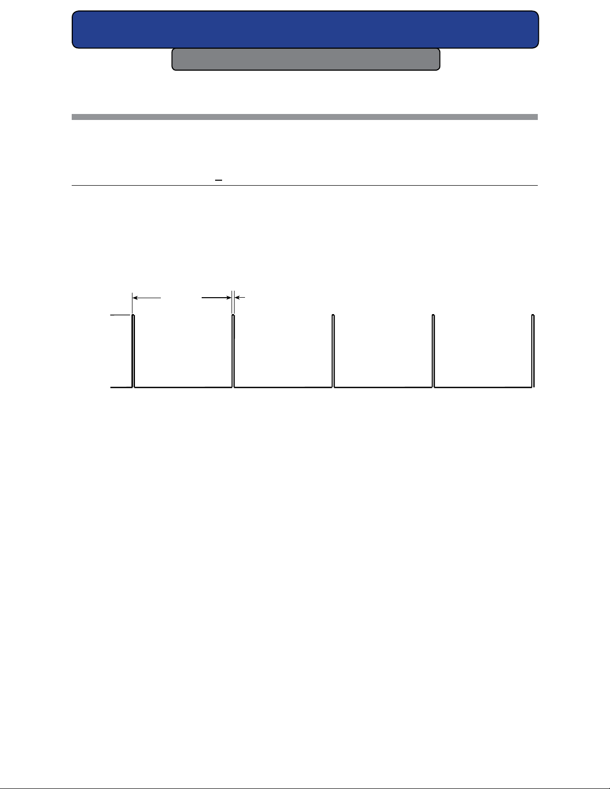
The UC-2000 does not produce tickle pulses continuously, but generates them only when the
PWM signal is low. Tickle pulses are sent one tickle period, 200 µs, after the falling edge of a
PWM signal pulse. Figure below illustrates tickle pulse parameters.
1 µs200 µs
5 VDC
0 VDC
Figure 4-3 Tickle pulse waveform.
32-1 lasers are designed to operate at a tickle frequency of 5 kHz, which allows the laser to
meet published specications. Tickle frequencies lower than 4.5 kHz may compromise laser
performance, particularly optical rise times, and stress the RF electronics thereby reducing
long term reliability while tickle frequencies greater than 5 kHz may cause unintended lasing.
Special care must be taken to maintain plasma ionization without lasing at tickle frequencies
greater than 5 kHz. When sending 1 µs tickle pulses at 5 kHz, PWM signals can be sent at an
independent, higher frequency but must go to near zero (< 1%) duty cycle to ensure laser
turn-o.
Pulse width modulation (PWM)
Pulse Width Modulation, or PWM, controls laser power by varying the duty cycle of the laser’s
RF ampliers, which in turn control the time-averaged RF power applied to the laser. Because
laser output follows PWM input with a rise and fall time constant of ~100 µs, the laser cannot
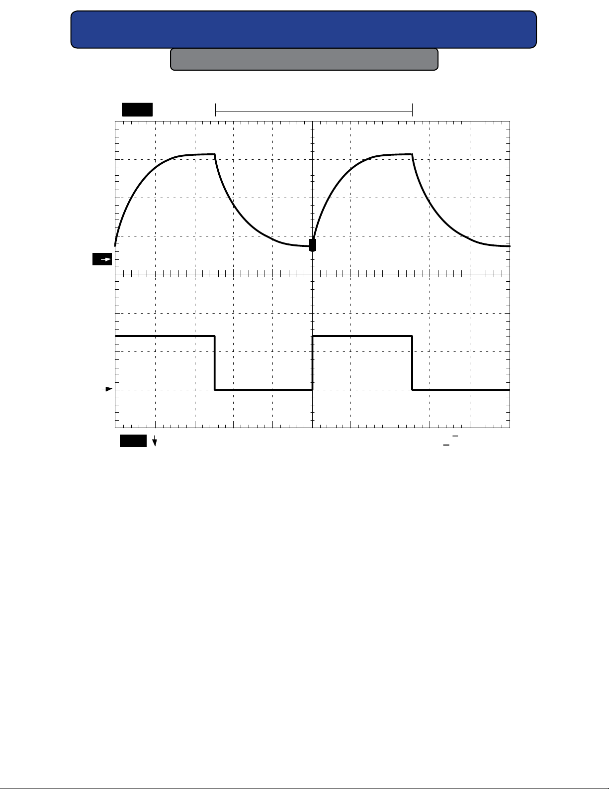
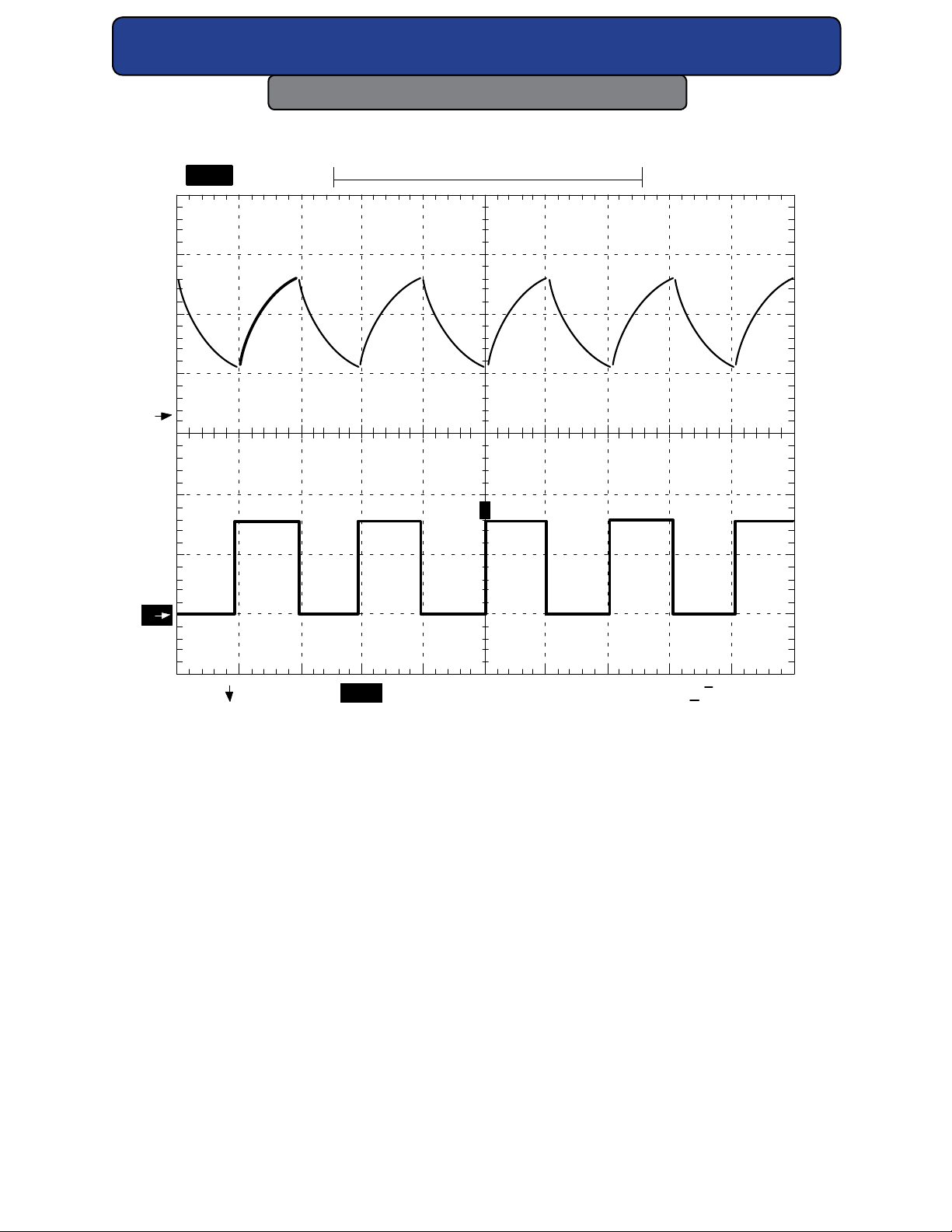
precisely follow PWM signal frequencies over 5 kHz with duty cycles greater than 50%. Typically, the depth of modulation for a 50% duty cycle is 90 to 100% at 2 kHz and 60 to 80% at 5
kHz. The following gure shows 32-1 optical waveforms at two dierent modulation frequencies.
SYNRAD® 32-1 Operator’s Manual Version 2.2
37
Page 38
Technical Reference
Ch2 Freq
2.008kHz
Low signal
amplitude
Ch2 +Duty
49.4%
Low signal
amplitude
2
1
Tek
User I/O Connections
79 Acqs
step
1
500kS/sTek
T
T
2
Ch 1
100mV
Ch 2
2 kHz Modulation
Figure 4-4 32-1-2 kHz waveform. The upper waveform is laser output, the lower wave
form is PWM input.
1 V
M
100
µS
Ch 2
/
740m V
SYNRAD® 32-1 Operator’s Manual Version 2.2
38
Page 39
Technical Reference
Ch2 Freq
4.906kHz
Low signal
amplitude
Ch2 +Duty
50%
Low signal
amplitude
User I/O Connections
34 Acqs
500kS/s
T
1
Tek
step
T
2
Ch 1
100mV
Ch 2
5 kHz Modulation
Figure 4-5 32-1-5 kHz waveform. The upper waveform is laser output, the lower wave
form is PWM input.
2 V
M
100
µS
Ch 2
720m V
/
SYNRAD® 32-1 Operator’s Manual Version 2.2
39
Page 40
Technical Reference
User I/O Connections
32-1 lasers are designed to operate at PWM signal base frequencies up to 20 kHz; however,
the choice of PWM frequency depends on the user’s specic application. In the majority of
laser applications, the UC-2000’s default PWM signal frequency of 5 kHz has proven to work
well. When considering PWM frequencies at 5 kHz or below, please review Marking/engraving
operation later in this chapter.
For high-speed motion applications that cannot tolerate any ripple in the optical beam response but still need adjustable power levels, we recommend the use of higher PWM frequencies, up to 20 kHz maximum. At 20 kHz, the laser’s optical beam response no longer follows
the PWM input and is very nearly a DC value with just a small amount of ripple present.
Warning
Serious
personal
injury
Always use shielded cable when connecting your PWM signal
source to the laser’s PWM connections.
In electrically-noisy environments, long lengths of unshielded
wire act like an antenna and may generate enough voltage to
trigger uncommanded lasing.
PWM signal
The modulated PWM signal applied to 32-1 lasers has three parameters: signal amplitude,
base frequency, and PWM duty cycle. By changing these parameters, you can command the
beam to perform a variety of marking, cutting, welding, or drilling operations.
The rst PWM signal parameter, signal amplitude, is either logic low—corresponding to laser
beam o, or logic high—corresponding to beam on. The laser o voltage, typically 0 V, can
range from 0.0 V to +0.5 VDC while the laser on voltage, typically 5 V, can range from +3.5 V to
10.0 VDC.
Base frequency, the second parameter, is the rate at which the amplitude is switched between
its low and high logic states. The standard base frequency is 5 kHz, which has a period of 200
µs. Maximum PWM frequency is 20 kHz.
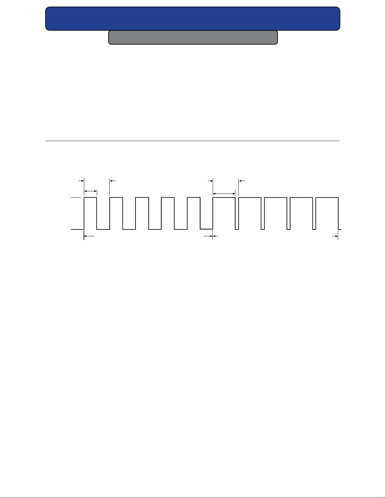
The third PWM signal parameter, PWM duty cycle, is the percentage of the period that the
PWM signal is high. If the PWM signal’s amplitude (at 5 kHz) is high for 100 µs and low for 100
µs, it has a 50% duty cycle; if the amplitude is high for 190 µs and low for 10 µs, it has a 95%
duty cycle. The following gure illustrates PWM signal parameters while the following table
lists PWM signal specications.
SYNRAD® 32-1 Operator’s Manual Version 2.2
40
Page 41
Technical Reference
User I/O Connections
Table 4-5 PWM signal specications.
Laser State Minimum Nominal Maximum
Laser O Voltage 0.0 VDC 0.0 VDC +0.5 VDC
Laser On Voltage +3.5 V +5.0 VDC +10.0 VDC
Current (@ 5 VDC) — — — — 6 mA (32-1)
Frequency Range 0 Hz (DC) 5 kHz 20 kHz
Duty Cycle 0% — — 100%
200 µs
100 µs
5 VD C
0 VD C
5kHz PWM Signal at 50% Duty Cycle 5kHz PWM Signal at 95% Duty Cycle
200 µs
190 µs
Figure 4-6 PWM signal waveform.
Operating modes
External control
In addition to controlling your 32-1 laser using a UC-2000 Controller, controlling the laser
externally, without a UC-2000, is also possible. The two primary elements of laser control are
gating, the ability to turn the laser on and o at the appropriate times, and power, the ability
to control the laser’s output energy. Both gating and power can be handled by a device such
as a personal computer, Programmable Logic Controller (PLC), or a function generator capable
of sending PWM pulses at the proper time (gating) and with the proper duty cycle (power).
Analog voltage or analog current control
Although 32-1 lasers cannot be controlled directly by analog voltage or current signals, this
type of control is possible when using the UC-2000 Controller. The Controller is connected
normally to the laser and analog voltage or current signals sent to the UC-2000’s ANV/C connector then control both gating and power.
SYNRAD® 32-1 Operator’s Manual Version 2.2
41
Page 42

Technical Reference
User I/O Connections
To generate the correct analog voltage from a computer or PLC, a Digital-to-Analog (D/A or
DAC) card capable of generating 0 V (laser o) to 10 V (maximum laser power) must be installed. To generate the proper analog current, install a D/A card that can generate 4 mA (laser
o) to 20 mA (maximum power). Software able to control your analog output card is required
for both congurations.
UC-2000 Universal Laser Controller
SYNRAD® recommends using a UC-2000 Universal Laser Controller to generate tickle pulses
and Pulse Width Modulated (PWM) signals to control the laser’s output power. The UC-2000
requires 15–50 VDC @ 35 mA, supplied from either its wall plug transformer or from the Auxiliary Power connector on the side of 32-1 lasers. Refer to the UC-2000 Laser Controller Operator’s Manual for information about UC-2000 operation.
To connect a UC-2000 Controller (available separately from SYNRAD), perform the following
steps:
1 Remove DC power from the laser. Fabricate a suitable DB-9 plug so Pin 3, PWM Positive,
connects to the center pin of the BNC and Pin 4, PWM Negative, connects to the shield.
2 If your system does not provide an enable input to the DB-9 plug, then jumper Pin 6,
remote keyswitch to Pin 7, remote keyswitch Out.
3 Connect the DB-9 plug to the DB-9 I/O connector on the rear of the laser.
4 Connect the miniature DC power plug on the UC-2000’s Power/Control cable to the min-
iature connector on the wall plug transformer cable.
5 Connect the mini-DIN connector on the other end of the UC-2000’s Power/Control cable
to the Laser connector on the UC-2000’s rear panel.
Continuous wave (CW) operation
In some applications, such as high speed marking or cutting, the time constant of the laser
and the PWM modulation causes a series of dots that may be visible on the marking surface
instead of a “clean” line. Operating the laser in CW mode will prevent this behavior from occurring. To operate the laser in CW mode, a constant +5 VDC signal is applied to the PWM input(s)
of the laser. This constant voltage source forces the internal switching electronics to remain
on, providing continuous and uninterrupted laser output power.
For pure CW operation, a steady +5 V signal can be applied through this connector (a tickle
signal must be applied during laser-o periods). This input is optically-isolated from the chassis and power supply ground circuit, but must not be subjected to common mode voltages
greater than ±50 VDC from chassis ground. The 32-1 laser has one PWM input that should
always be driven identically from the signal source by using a “Y” cable.
SYNRAD® 32-1 Operator’s Manual Version 2.2
42
Page 43
Technical Reference
User I/O Connections
Gated operation
In many marking and cutting applications, the laser is required to pulse, or gate, on and o in
synchronization with an external control signal (typically from a computer or function generator operating in the range from DC to 1 kHz). To pulse or gate the laser, connect a signal
providing +5.0 VDC pulses to the Gate connector on the rear panel of the UC-2000.
Users who intend to use a gating signal should set the UC-2000’s gate input logic to internal
Pull-Down (normally o) mode. This prevents the beam from being enabled unless a high level (+3.5 V to +5.0 VDC) signal is applied to the Gate input connector. In the pull-down (normally o) mode an asserted logic low state, short circuit to ground, or an open or disconnected
Gate input locks the beam o.
Many CO lasers operating in applications requiring short gating pulses at repetition rates
below 500 Hz will exhibit some leading edge overshoot regardless of the PWM frequency. This
occurs because a cooler lasing medium (the CO gas) is more ecient than a hotter one. This
overshoot is more pronounced at lower gating frequencies since the gas has a longer time to
cool down between PWM signal pulses.
Warning
Serious
personal
injury
Note:
When operating in CW mode, laser power output cannot be adjusted. If you require
an adjustable output power level, refer to the Pulse width modulation (PWM) section for information regarding high frequency operation.
The UC-2000’s default gate logic is factory set to internal Pull-Up
(normally on) mode so that an open (disconnected) Gate input
causes the laser to turn on. This functionality allows the user to
easily test and verify laser operation prior to integration.
In an integrated system, you should congure the UC-2000’s
gate input logic to internal Pull-Down (normally o) mode. This
prevents the beam from being enabled unless a high level (+3.5
V to +5.0 VDC) signal is applied to the Gate input connector. In
the Pull-Down (normally o) mode, an asserted logic low signal,
short circuit to ground, or an open or disconnected Gate input
locks the beam o.
SYNRAD® 32-1 Operator’s Manual Version 2.2
43
Page 44
Technical Reference
User I/O Connections
Caution
Possible
Equipment
Damage
Do not ground the Remote Keyswitch input to an external circuit—
this will damage laser circuitry. Any external circuit(s) connected to
these terminals must be oating with respect to ground. We recommend using “dry circuit” (zero voltage) switches or relay circuitry.
DB-9 connections
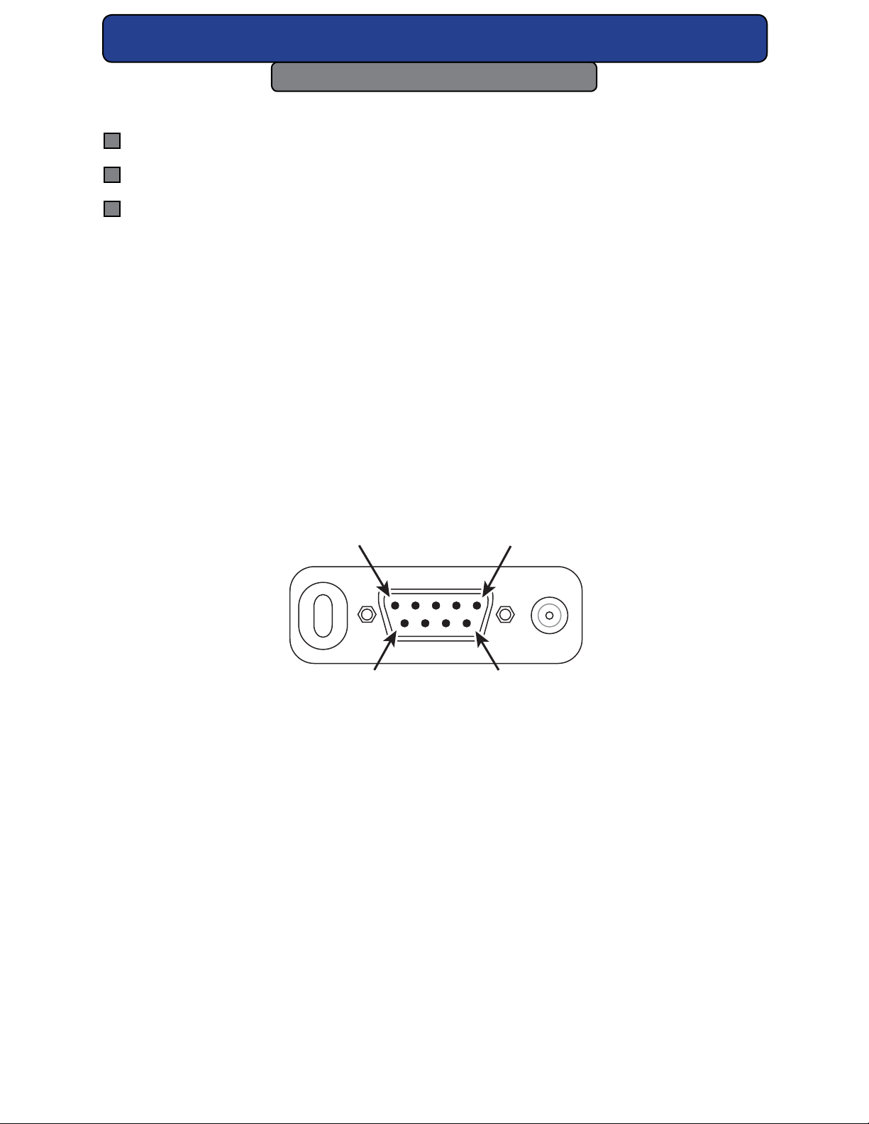
32-1 lasers are equipped with a female DB-9 connector mounted to the sidewall of the laser.
The DB-9 connector provides the user with a convenient method for monitoring fault conditions (over temperature, control/RF circuitry failure, etc.) and adds, remote keyswitch (relay or
switch), and remote LED indicator capability. These signals allow you to connect remote keyswitch, LASE, and ready (PWR) indicators to a remote operator’s station or connect a remote
interlock safety switch to interlock equipment doors or panels.
Note:
You can control 32-1 lasers from an alternate user-supplied PWM signal source. See
Controlling laser power in the Technical Reference chapter for control signal descriptions.
SYNRAD® 32-1 Operator’s Manual Version 2.2
44
Page 45
Technical Reference
DB-9 Connector
PIN 9
PIN 6
User I/O Connections
User I/O connections
User I/O connection summary
Input/output signals
Sample I/O circuits
The PWM signal and all input/output (I/O) control signals are connected to the User I/O port.
Please refer to the gure below for the 9 pin female D-type sub-miniature connector on the
side of the laser. The gure below illustrates the pin arrangement of the User I/O connector.
DB-9 connections
The gure below shows the physical layout and pin identication of the 32-1 DB-9 Connector.
Refer to the following tables in the next two pages describing input/output signal specications.
Figure 4-7 Physical layout of 32-1 DB-9 Connector.
PIN 5
PIN 1
SYNRAD® 32-1 Operator’s Manual Version 2.2
45
Page 46

Technical Reference
User I/O Connections
I/O Fault Diagrams
Table 4-6 DB-9 pin assignments.
Pin# Function & Description
1 Fault Shutdown Output
Indicates failure of internal circuitry or existence of over temperature (> 60 °C ±2 °C),
over voltage, or under voltage fault. This active low signal (referenced to Pin 2 or Pin 4)
transitions from +15 V (normal operation) to 0 VDC when a fault occurs. Use this output signal to disable external processes during a fault1. See the two following table(s)
for output signal specications.
2 Signal Ground
Signal ground/chassis ground for Pins 1, 8, and 9.
3 PWM (+)
4 PWM (-)
5 No Connection
6 Remote Keyswitch Input
Connect a remote relay or switch in series with the laser Keyswitch (If customer installed) to control laser On / O / Reset functions. Connect Pin 6 to Pin 7 to run; open
this connection to halt lasing or reset faults. As shipped, Pins 6 and 7 are connected by
the factory-installed jumper plug to enable the Remote Keyswitch function
two following table(s) for input signal specications.
7 Remote Keyswitch Output
Connect Pin 7 to Pin 6 to enable the Remote Keyswitch function (see Pin 6 description
above). Pin 7 is at DC line potential (+30 VDC) only when the Keyswitch is set to ON.
As shipped, Pins 6 and 7 are connected by the factory-installed jumper plug
two following table(s) for output signal specications.
8 Remote Lase LED Output
Connect an LED or LED-optoisolator between Pin 8 and Signal Ground for a remote
LASE indication
5,6
. See the two following table(s) for output signal specications.
9 Remote Ready LED Output
Connect an LED or LED-optoisolator between Pin 9 and Signal Ground for a remote
Ready (PWR) indication5. See the two following table(s) for output signal specications.
2,3
. See the
3,4
. See the
1 Pin 1 is an active low output. Specications: OFF: +15 VDC, 5 mA into 3 kOhm. ON: < 1 VDC, sinking 100 mA.
2 “Dry-circuit” (zero voltage) external switches are required since current into debounced remote keyswitch pins is negligible.
3 The remote keyswitch output pin is not current-limited or fused.
4 Pins 8 and 9 can be directly connected to the anodes of LEDs or LED-input optoisolators without external current limiting devices. Con-
nect LED cathodes to Pin 2. Current is limited internally to 20 mA at 3.3 V maximum.
5 The output of Pin 8, the Remote Lase LED Output, is a Pulse Width Modulated (PWM) signal based on the PWM input signal. It is not a
steady state (on/o) output.
SYNRAD® 32-1 Operator’s Manual Version 2.2
46
Page 47

Technical Reference
User I/O Connections
Table 4-7 DB-9 Connector input signal specications.
Pin # Input Signal Name Input Specications
3 PWM (+) Apply a 5VDC Pulse Width Modulated (PWM) signal to the
4 PWM (-) laser’s control input connector.
6 Remote Keyswitch Input Circuit” (zero-voltage) external switches to prevent inter-
nal circuit damage.
Table 4-8 DB-9 Connector output signal specications.
Pin # Output Signal Name Output Specications
1 Fault Shutdown Output Active Low output signal: O: + 15 VDC, 5 mA into 3
kOhm;
7 Remote Keyswitch Output 50 mA maximum @ 30 VDC. Output active (+30 VDC)
when Keyswitch ON or bypassed (OEM models).
8 Remote Lase LED Output Current-limited to 11 mA @ 2.4 VDC maximum. Voltage
output is pulse width modulated at input PWM
signal frequency, not a steady state on/o signal.
9 Remote Ready LED Output Current-limited to 11 mA @ 2.4 VDC maximum.
2 Signal Ground Signal ground for pins 1, 8, and 9.
SYNRAD® 32-1 Operator’s Manual Version 2.2
47
Page 48

Technical Reference
User I/O Connections
Sample DB-9 Connector I/O circuits
Sample input circuits
The gure below illustrates a method of connecting a relay contact or limit switch to act as a
remote keyswitch. Remember that Remote Keyswitch and Remote Interlock inputs are “dry
circuit” or zero-voltage inputs.
DB-9 CONNECTOR PINS
(7) REMOTE KEYSWITCH
RELAY CONTACT OR
LIMIT SWITCH
Figure 4-8 Remote Keyswitch circuit.
OUTPUT
(6) REMOTE KEYSWITCH
INPUT
SYNRAD® 32-1 Operator’s Manual Version 2.2
48
Page 49
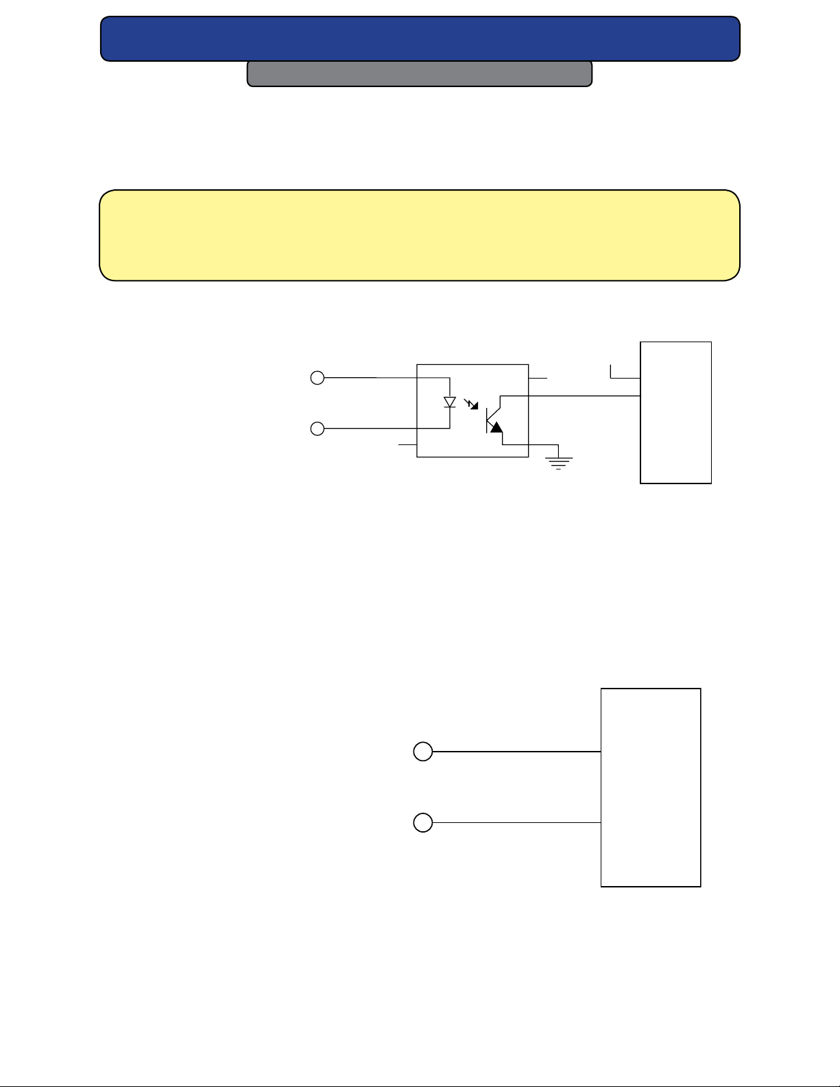
Technical Reference
PLC
User I/O Connections
Sample output circuits
Figures below illustrate how to connect the laser’s Remote Ready LED Output to a Programmable Logic Controller (PLC) DC input module using current sourcing, current sinking, and
resistive pull-up methods.
Note: You can use these same circuits to monitor the laser’s Remote Lase LED Output
(DB-9, Pin 8); however, the Remote Lase LED Output is not a steady state (on/o)
output. It is a Pulse Width Modulated (PWM) signal based on the PWM input signal
to the laser.
PLC
DB-9 CONNECTOR PINS
(9) REMOTE READY
LED OUTPUT
4N29 OPTOISOLATOR
1
6
5
NC
+24 VDC
INPUT
RTN
NC
2
3
4
24 VDC GND
(2) SIGNAL GROUND
Figure 4-9 Remote Ready output to PLC input (PLC sourcing).
The following gure illustrates how to connect the Fault Shutdown Output signal to a PLC.
The Fault Shutdown Output function signals a laser shutdown due to an under/over voltage
condition, an over temperature condition, or failure of internal circuitry.
DB-9 CONNECTOR PINS
(1) FAULT SHUTDOWN
INPUT
OUTPUT
(2) SIGNAL GROUND
Figure 4-10 Fault Shutdown Output to PLC input.
RTN
SYNRAD® 32-1 Operator’s Manual Version 2.2
49
Page 50
Technical Reference
Integrating 32-1 safety features
The Integrating 32-1 safety features section includes subsections:
Remote Keyswitch functions
The 32-1 DB-9 Connector allows system integrators or end-users to integrate 32-1 laser safety
features into their control system. In particular, the 32-1 Remote Keyswitch function serves to
disable DC power to the laser’s RF driver. Without power, the RF driver cannot supply PWM or
tickle signals to the resonator, causing the CO gas to remain in a zero-energy state.
Important
Pin 9, the Remote Ready LED Output, is a current- and voltage-limited output
Note:
meant only for direct connection to an LED or LED-input optoisolator.
OEM lasers
On OEM lasers, 5-seconds after power-up DC power is applied to the RF driver. To reset a fault
condition, remove DC power for 30 seconds and then reapply power to the laser or toggle
(open, then close) the Remote Keyswitch signal via pins 6 and 7 on the DB-9 Connector. To use
this “remote reset” functionality, open and then close a “dry-circuit” (zero voltage) switch or
relay contact between Pin 6, Remote Keyswitch Input, and Pin 7, Remote Keyswitch Output.
Reconnecting Pin 6 to Pin 7 applies power to the RF driver and begins a ve-second delay
after which lasing is enabled.
Your control system can monitor the laser’s power-on status through the DB-9 Connector by
connecting your system’s input between Pin 9, Remote Ready LED Output, and Pin 2, Signal
Ground. The Remote Ready LED Output goes active when the laser is enabled, indicating that
lasing is possible after the ve-second delay. The output is inactive when lasing is disabled.
Refer back to the, DB-9 pin assignment tables for specic details.
Note:
32-1 lasers may be hard-mounted to equipment by removing several of the bottom panel screws and replacing these with longer screws to secure the laser to
optical assemblies. This mounting method is only recommended as long as the
screws do not support the weight of the laser. For a sturdier attachment, the laser
may be clamped to optical assemblies by applying clamping forces between top
and bottom cover screws. Do not apply clamping forces on the longitudinal centerline.
SYNRAD® 32-1 Operator’s Manual Version 2.2
50
Page 51
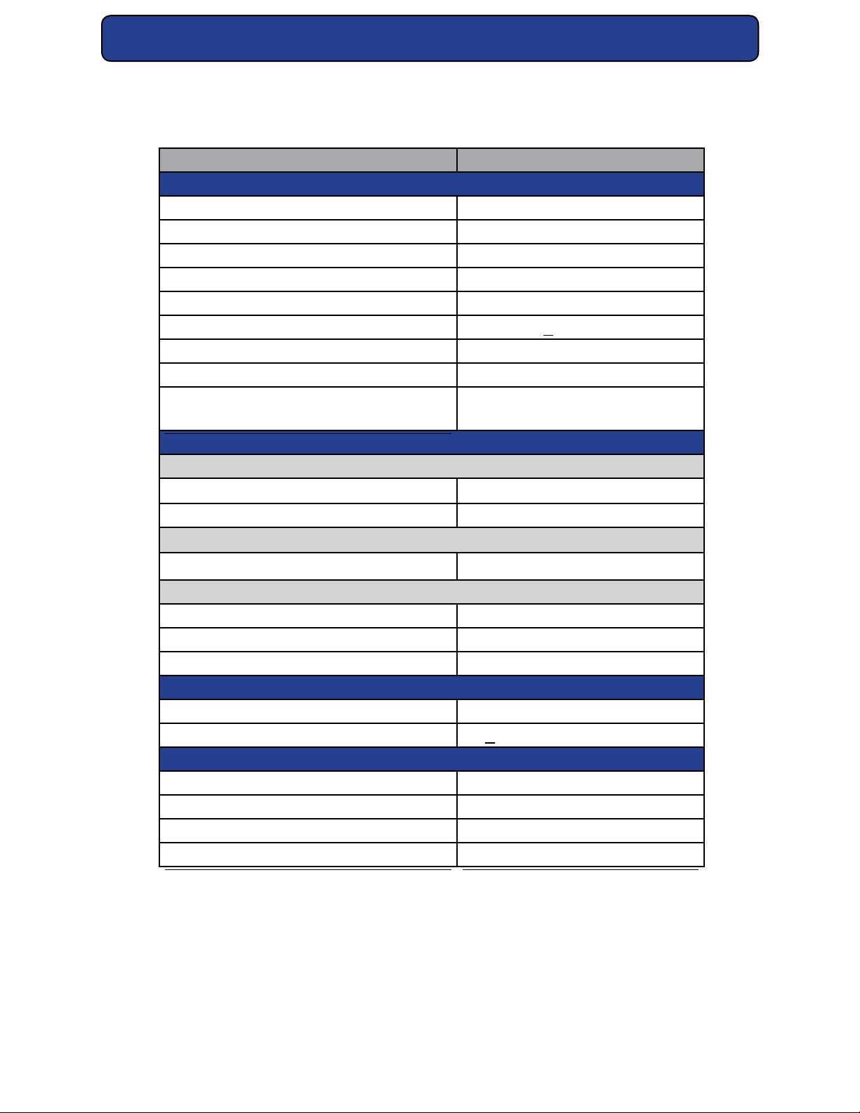
Technical Reference
General Specications
Table 4-9 Model 32-1 general specications.
Parameter 32-1 (10.6 µm)
Output Specications
Wavelength (microns µm) 10.57µm-10.63 µm
Power Output 5 W
Power Stability3 (Cold Start) ±15%
Mode Quality
Beam Diameter, mm (at 1/e2)4 2.3 mm ± 0.5 mm
Beam Divergence, full angle < 8.0 mrad
Ellipticity < 1.2
Polarization Random
Rise Time (Measured at 1 kHz, 50% duty
cycle)
Input Specications
Power Supply
3
†
M2 ≤ 1.2
< 150 µs
Voltage 30 VDC ± 2.0 VDC
Maximum current 4.0 A
Input Signals
Frequency DC- 25kHz
Cooling Specications
Maximum Heat Load 150 Watts
Maximum Tube Temperature 60 °C
Minimum Flow Rate 150 CFM per fan two (2) required
Environmental Specications
Operating Ambient Temperature Range 5 °C - 40 °C
Humidity < 80% RH, non-condensing
Physical Specications
Length 11.2 in (284 mm)
Width 2.8 in (71 mm)
Height 4.2 in (106 mm)
Weight 7.0 lbs (3.18 kg)
Specications subject to change without notice.
† Typical. Actual wavelength range may vary from 10.2–10.8 µm.
1 This power level is guaranteed for 12 months regardless of operating hours.
2 Minimum 30 VDC input voltage to obtain guaranteed output power.
3 From cold start (guaranteed) at 95% duty cycle.
4 Measured at laser output.
5 32-1 lasers are designed to operate at a tickle frequency of 5 kHz, which allows the laser to meet published specications. Tickle frequencies lower than
4.5 kHz may compromise laser performance, particularly optical rise times, and stress the RF electronics thereby reducing long term reliability while
tickle frequencies greater than 5 kHz may cause laser emission.
6 FCC and CE tested at 5 kHz.
SYNRAD® 32-1 Operator’s Manual Version 2.2
51
Page 52
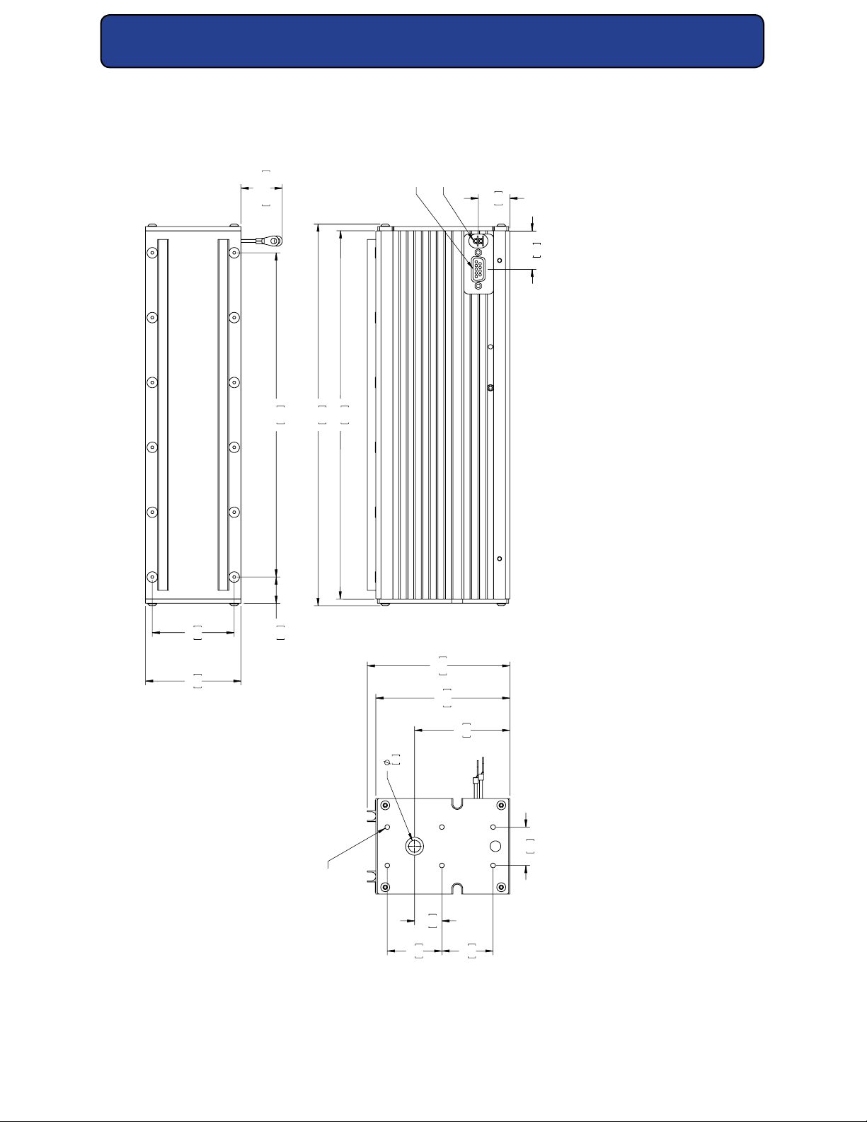
Technical Reference
FACE OF FRONT PLATE
6X 8-32 UNC THREAD
SCREW CANNOT EXTEND
.3 [8] MAX. BEYOND
DIMENSIONS IN [ ] ARE MILLIMETERS.
Outline and Mounting Diagrams
±1
40.0
±25
1016
241
9.500
11.17
284
10.79
274
CONTROL I/O
9-PIN D-SUB
DC INPUT WITH
IN-LINE FUSE
(NOT SHOWN)
23
.925
1.12
28
61
2.400
71
2.80
NOTES:
1.
20
.77
106
4.18
100
3.93
71
2.792
.350
9
BEAM EXIT
29
1.125
20
.800
1.600
41
1.500
38
Figure 4-11 Model 32-1 package outline and mounting dimensions, 1 of 1.
SYNRAD® 32-1 Operator’s Manual Version 2.2
52
Page 53
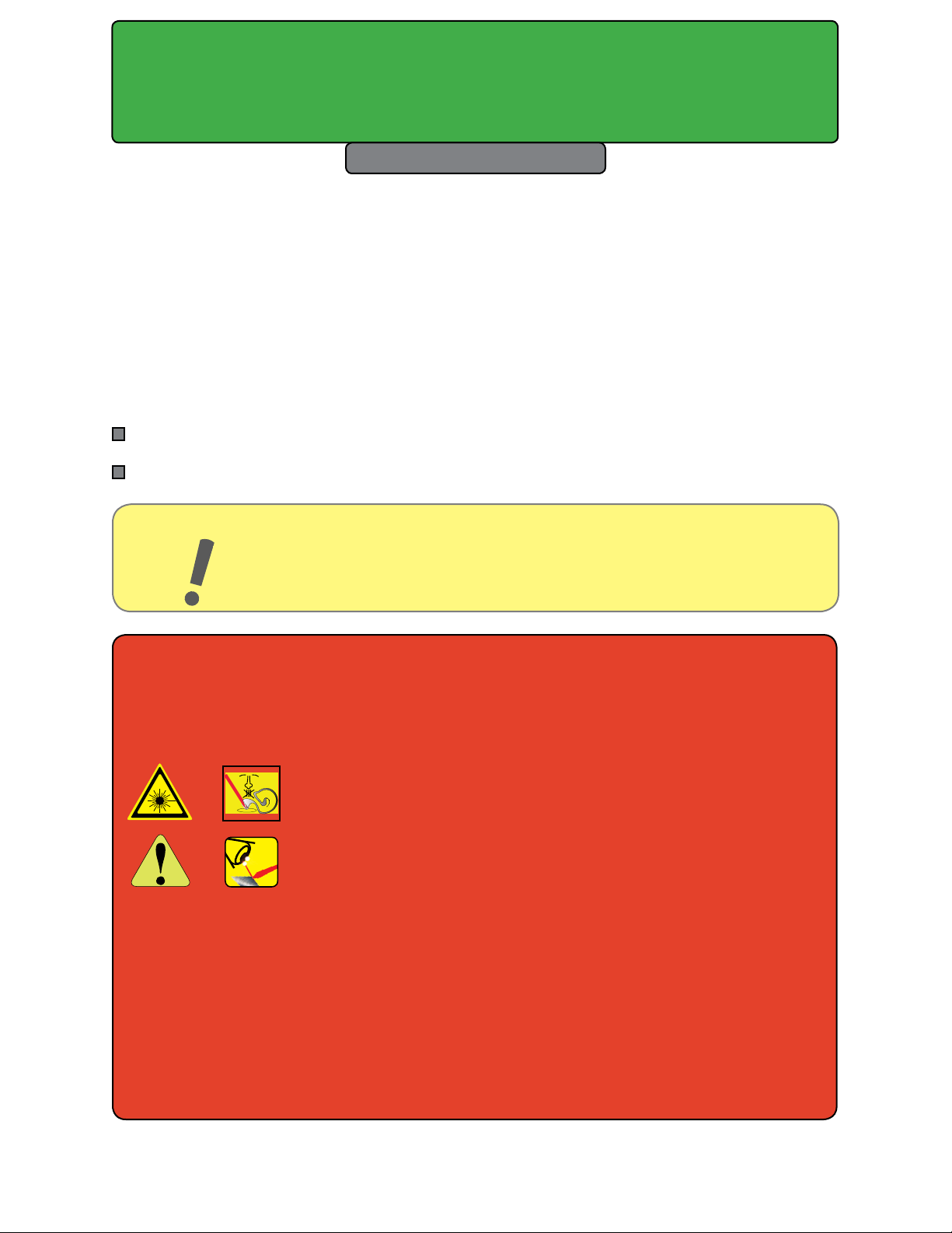
Maintenance/
Troubleshooting
Maintenance
5
Maintenance and Troubleshooting
Introduction
Maintenance – describes typical 32-1 series maintenance procedures.
Troubleshooting – explains how to troubleshoot common 32-1 series problems.
Important
Note:
Warning
Serious
personal
injury
The use of aerosol dusters containing diuoroethane causes “blooming”, a condition
that signicantly expands and scatters the laser beam. This beam expansion can aect
mode quality and/or cause laser energy to extend beyond the connes of optical elements in the system, possibly damaging acrylic safety shielding. Do not use air dusters
containing diuoroethane in any area adjacent to CO2 laser systems because diuo-
roethane persists for long time periods over wide areas.
This section of the Operation Manual explains how to conduct regular maintenance and/or basic troubleshooting to 32-1 lasers. If you cannot attend to
the unit using the information described in this manual, contact SYNRAD®,
(+.425.349.3500) or an authorized SYNRAD Distributor.
This Class 4 laser product that emits invisible infrared laser radiation in the 10.6 µm CO2 wavelength band.
Because direct or diuse laser radiation can inict severe corneal
injuries, always wear eye protection when in the same area as an
exposed laser beam.
Do not allow the laser beam to contact a person.
This product emits an invisible laser beam that is capable of seriously burning human tissue.
Always be aware of the beam’s path and always use a beam block
while testing.
A risk of exposure to toxic elements, like zinc selenide, may result when certain
optical or beam delivery components are damaged. In the event of damage to laser,
marking head, or beam delivery optics, contact SYNRAD, or the optics manufacturer for
handling instructions.
SYNRAD® 32-1 Operator’s Manual Version 2.2
53
Page 54
Maintenance/
Troubleshooting
Maintenance
Maintenance
Disabling the 32-1 laser
Daily inspections
Storage/shipping
Cleaning optical components
Disabling the 32-1 laser
Before performing any maintenance on your laser, be sure to completely disable the laser by
disconnecting the DC Power Cables from the DC power supply.
Daily inspections
Perform the following steps daily to keep your laser in optimum operating condition. Except
for the procedures described below, no other service is required or should be attempted.
Warning
Serious
personal
injury
1 Inspect beam delivery components for signs of dust or debris and clean as required.
When cleaning the optical surfaces of beam delivery components, carefully follow the
manufacturer’s instructions.
2 Visually inspect the exterior housing of the laser to ensure that all warning labels are
present. Refer to the Laser Safety chapter for label types and locations.
A risk of exposure to toxic elements, like zinc selenide, may result when certain optical or beam delivery components are damaged. In the event of damage to laser, marking head, or beam
delivery optics, contact SYNRAD or the optics manufacturer for
handling instructions.
Ensure that DC power to the laser is turned o and locked out
before inspecting optical components in the beam path.
Invisible CO2 laser radiation is emitted through the aperture.
Corneal damage or blindness may result from exposure to laser
radiation.
SYNRAD® 32-1 Operator’s Manual Version 2.2
54
Page 55
Maintenance/
Troubleshooting
Maintenance
Storage/shipping
Refer to Packaging instructions in the Technical Reference chapter and/or appropriate quick
start guide for detailed instructions on properly packaging the laser for shipment.
If you no longer have the original shipping box and inserts, contact SYNRAD® Customer Service about purchasing replacement packaging.
Important
Note:
Caution
Possible
Equipment
Damage
Debris or contaminants on the laser’s output coupler or external beam delivery components
may aect laser processing and lead to damage or failure of the optics and/or the laser. Carefully follow the steps below to inspect and clean the optical components in the beam path.
Before beginning the cleaning process, read this entire section thoroughly to ensure that all
cleaning materials are available and that each step is completely understood.
Important
Note:
Failure to properly package the laser using SYNRAD-supplied shipping boxes
and foam/cardboard inserts as shown in the Packaging instructions may void
the warranty. Customers may incur additional repair charges for shipping damage caused by improper packaging.
Even small amounts of contamination on optics in the beam
path can absorb enough energy to damage the optic.
Inspect beam delivery optics periodically for signs of contaminants
and carefully clean as required.
Exercise great care when handling infrared optics; they are much more fragile
than common glass materials. Optical surfaces and coatings are easily damaged by rough handling and improper cleaning methods.
SYNRAD® 32-1 Operator’s Manual Version 2.2
55
Page 56

Maintenance/
Troubleshooting
Maintenance
Cleaning guidelines
Before using any cleaning agents, read Safety Data Sheets (SDS) and observe all nec-
essary safety precautions.
Wear latex gloves or nger cots (powder-free) to prevent contamination of optical
surfaces by dirt and skin oils.
Never handle optics with tools; always use gloved hands or ngers.
Hold optics by the outer edge; never touch the coated surface.
Always place optics on a tissue or suitable equivalent material for protection; never
place optics on hard or rough surfaces.
It may be necessary to use a cotton ball or ued cotton swab instead of a lens wipe
to uniformly clean the entire surface of small-diameter mounted optics.
Required cleaning materials
The table below lists the type and grade of materials required to properly clean optical surfaces.
Table 5-1 Required cleaning materials.
Cleaning Material Requirements
Latex gloves or nger cots Powder free
Air bulb Clean air bulb
Ethyl or isopropyl alcohol Spectroscopic or reagent grade
Acetone Spectroscopic or reagent grade
Lens wipe (preferred) Optical (cleanroom) quality
Cotton balls or cotton swabs High-quality surgical cotton/high-quality paper-bodied
SYNRAD® 32-1 Operator’s Manual Version 2.2
56
Page 57
Maintenance/
Troubleshooting
Maintenance
Cleaning optics
1 Shut o and lock out all power to the laser. You must verify that the laser is OFF (in a
zero-energy state) before continuing with the optical inspection!
2 Visually inspect all optical surfaces in the beam path for contaminants.
3 Remove loose contaminants from the optic by holding a clean air bulb at an angle to
the optic and blow a stream of air at a glancing angle across the lens surface. Repeat
as necessary.
4 Dampen a lens wipe with the selected cleaning agent. Alcohol (least aggressive) is
best for initial surface cleaning. Acetone (moderately aggressive) is best for oily resi-
due or minor baked-on vapors and debris.
5 Gently, and without applying pressure, drag the damp lens wipe across the optical
surface in a single pass. Do not rub or apply any pressure, especially when using a
cotton swab. Drag the wipe without applying any downward pressure.
6 Carefully examine the optic under suitable lighting. Certain contaminants or damage
such as pitting cannot be removed. In these cases the optic must be replaced
to prevent catastrophic failure.
7 Repeat Steps 4 through 6 as required, removing all traces of contaminants and depos-
its.
Important
Note:
Caution
Possible
Equipment
Damage
If acetone is used as a cleaning solvent, a second follow-up cleaning of the
optical surface using alcohol is required to remove any acetone residue.
Use a clean lens wipe on each pass. The wipe will pick up and carry surface
contaminants that may scratch optical surfaces or coatings if reused.
Do not allow the nozzle of the air bulb to touch the optical surface. Any contact may damage the optic by scratching coatings on
the optical surface.
Do not use compressed shop air to blow contamination from the
optic. Compressed air contains signicant amounts of water and oil
that form adsorbing lms on the optical surface.
Do not exert pressure on the surface of the optic during cleaning.
Optical surfaces and coatings are easily scratched by dislodged contaminants.
Use a new lens wipe on each pass as contaminants picked up by
the wipe may scratch the optical surface.
SYNRAD® 32-1 Operator’s Manual Version 2.2
57
Page 58
Maintenance/
Troubleshooting
Troubleshooting
Troubleshooting
Introduction
Resetting faults
Laser faults
Beam delivery optics
Troubleshooting Introduction
This section is designed to help isolate problems to the module level only. Problems on circuit
boards or the laser tube are not within the scope of this guide because they are not user-serviceable assemblies; do not attempt to repair them. Contact SYNRAD® or a SYNRAD Authorized Distributor for repair or replacement information.
To troubleshoot the 32-1 laser, it is necessary to understand the sequence of events that must
happen before the laser can turn on and operate. Before you attempt to perform any service,
we advise you to read the entire troubleshooting guide and review the relevant schematic
diagrams. Symptoms and possible causes are highlighted by dark print and bullet points
throughout this section. Information about each symptom and cause can be found in the
paragraphs following each heading.
Caution
Possible
Equipment
Damage
The Power-On Reset feature is not available on OEM models; OEM customers must provide
this required safety feature as part of their equipment integration.
During any fault shutdown, the Fault Shutdown Output (Pin 1 on the DB-9 Connector), which
is normally at +15 VDC, latches to a low state (0 VDC) until the laser is reset by removing DC
power for 30 seconds and then reapplying power to the laser.
Attempting repair of a SYNRAD laser without the express authorization of SYNRAD, will void the product warranty. If troubleshooting
or service assistance is required, please contact SYNRAD Customer
Service.
Each Symptom listed below describes a particular fault condition. For each Symptom, specic
causes and solutions are described in the Possible Causes section.
Symptom:
No output beam, but +30 VDC is applied.
SYNRAD® 32-1 Operator’s Manual Version 2.2
58
Page 59

Maintenance/
Troubleshooting
Troubleshooting
Possible Causes:
A fault shutdown has occurred. Pin 1 on the DB-9 Connector is at 0 VDC in reference to
Pin 2 (Pin 1 is at +15 VDC during normal operation).
An over temperature, overvoltage/undervoltage, or RF circuitry failure has occurred.
Correct the problem(s), then remove power from the laser for 30-seconds. Re-apply power (if
a Keyswitch has been added through the DB-9 jumper plug), cycle the Keyswitch or Remote
Keyswitch.
Beam delivery optics
Symptom:
The laser appears to slowly lose power over time; laser output power must be in-
creased to maintain previous performance.
Possible Causes:
Beam delivery optics are coated by vapor residue or debris.
Shut down the laser and carefully inspect each optic in the beam delivery path, including the
laser’s output coupler. Remember that optics are fragile and must be handled carefully; preferably by the mounting ring only. If the optic requires cleaning, refer to the required cleaning
materials table earlier in this chapter, then refer back to Maintenance for cleaning instructions.
Use only recommended cleaning materials to prevent scratching delicate optical surfaces.
If the focusing optic is pitted, it must be replaced immediately. The laser’s high power density
will cause pits or debris on the lens to absorb enough energy that the lens may crack. If this
happens, other optics in the beam path may be contaminated or damaged as well.
When the application requires air (instead of nitrogen or argon) as an assist gas, we recommend the use of breathing quality air available in cylinders from a welding supply company.
Because compressed shop air contains minute particles of oil and other contaminants that
will damage optical surfaces, it must be carefully ltered and dried before use as a purge or
assist gas. Refer to Assist gas purity specications, in the Technical Reference chapter for lter-
ing specications.
Caution
Possible
Equipment
Damage
If you operate your laser or marking head in a dirty or dusty environment, contact SYNRAD® about the risks of doing so and the
precautions you can take to increase the longevity of your laser.
SYNRAD® 32-1 Operator’s Manual Version 2.2
59
Page 60
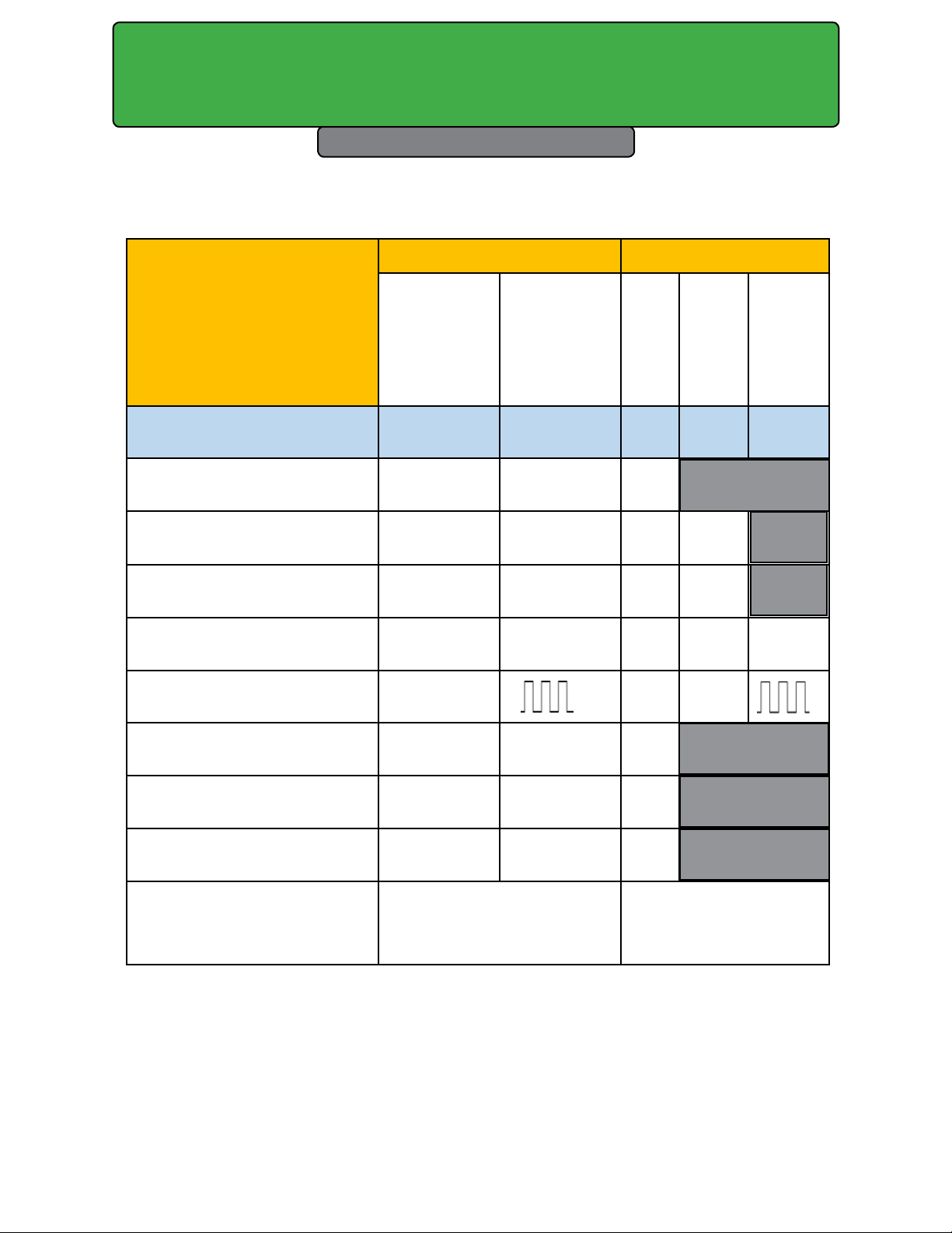
Maintenance/
LED and I/O States, 32-1 Series Lasers
Laser enabled, no tickle or
PWM
TABLE KEY:
H = output high/open
L = output low
OUTPUT STATUS
INPUT STATUS
DC Power Applied Laser
C = circuit closed
O = circuit open
x = Does not matter
Troubleshooting
Troubleshooting
Input/Output/Fault Conditions
LASER CONDITION /
FAULT
DB-9 pins
DC Power Off X X
Not Enabled
Tickle Applied C Tickle H ON Tickle
Laser Firing C H ON
Over Temp Fault X X L
PWM
Remote Key
6 to 7 3 to 4
O X
C None H ON
Fault
1 9 8
L
H ON
Ready LED
Lase LED
Under Voltage Fault X X L
Over Voltage Fault X X L
Table 5-2 Input/Output/Fault Conditions for the 32-1 series lasers.
SYNRAD® 32-1 Operator’s Manual Version 2.2
60
Page 61

Index
Chapter Index
A
American National Standards Institute (ANSI) 18
Assist gas purity
specications, 32, 34, 35
C
Caution
condensation, 5, 15, 27, 30, 55, 44, 57, 58, 36, 60
CDRH 21
Class IV safety features 24
Code of Federal Regulations (CFR) 21, 22
Customer Service 8
D
Daily inspections 54
DC Power cable 54
Dew point
chart, 46
Disabling Firestar 54
F
RoHS 23
S
Sales and Applications 8
Specications
assist gas purity, 32, 34, 35
Storage/shipping 55
T
Technical Support 8
Trademark information 6
Troubleshooting 55
U
User I/O
connection summary, 45
User I/O connections
input/output signals 45
W
Warranty information 7
Food and Drug Administration (FDA) 21
H
Hazard information 15
label locations, 20
terminology, 15
I
Inspections
dai ly, 54
L
Label locations 20
Laser Institute of America (LIA) 19
M
Maintenance
daily inspections, 54
disabling Firestar, 54
storage/shipping, 55
O
Occupational Safety and Health Administration (OSHA) 19
R
Reference materials 8
SYNRAD® 32-1 Operator’s Manual Version 2.2
61
Page 62

Index
Tables and Figures
Figure 1-1. 32-1 Ship kit contents. ...................................................................................11
Table 1-1. 32 ship kit contents. ......................................................................................... 11
Figure 1-2. Anatomy of a model number. .....................................................................13
Figure 2-2. Always wear safety glasses ........................................................................ 18
Figure 2-3. 38-1 Hazard label locations. ........................................................................ 20
Table 2-1. Class 4 safety features. ..................................................................................... 24
Table 2-2. European Union Directives. ........................................................................... 25
Figure 2-4. European compliance mark. ....................................................................... 25
Figure 2-5. 32-1 Declaration Document. ......................................................................26
Figure 3-1. Front panel controls & indicators. .............................................................28
Figure 3-2. Side panel controls & indicators. ..............................................................29
Figure 4-1. Beam characteristics. ....................................................................................32
Figure 4-2. “Flying optics” beam path. .........................................................................34
Table 4-2. Assist gas purity specications. ....................................................................35
Table 4-3. Input signal specications. ............................................................................ 36
Table 4-4. Tickle pulse specications. .............................................................................37
Figure 4-3. Tickle pulse waveform. .................................................................................. 37
Figure 4-4. 32-1-2 kHz waveform. ....................................................................................39
Figure 4-5. 32-1-5 kHz waveform. . ..................................................................................39
Table 4-5. PWM signal specications. .............................................................................41
Figure 4-6. PWM signal waveform. ................................................................................. 41
Table 4-6. DB-9 pin assignments. ..................................................................................... 47
Figure 4-7. Physical layout of 32-1 DB-9. ....................................................................... 48
Table 4-7. DB-9 input signal specications. .................................................................48
Table 4-8. DB-9 output signal specications. ..............................................................48
Figure 4-8. Remote Keyswitch circuit. ............................................................................ 49
Figure 4-9. Remote Ready output to PLC. .....................................................................50
Figure 4-1. Fault Shutdown Output to PLC input. .....................................................50
Table 4-9. Model 32-1 general specications. ............................................................. 52
Figure 4-11. Model 32-1 package O and M. ................................................................. 53
Table 5-1. Required cleaning materials. ........................................................................57
Table 5-2. LED and I/O states. ............................................................................................ 61
SYNRAD® 32-1 Operator’s Manual Version 2.2
62
 Loading...