

Page 1
Expansion Unit RXD1219sas
Hardware Installation Guide
Page 2

Table of Contents
Chapter 1: Before You Start
Package Contents 3
Synology RXD1219sas at a Glance
Hardware Specication
Optional Accessories
Safety Instructions
5
6
7
Chapter 2: Hardware Setup
Tools and Parts for Component Installation 8
Install Drives
Install and Remove Rail Kits
Connect with Synology Server
LED Indicator Table
8
15
Chapter 3: System Maintenance
Replace SAS Module 16
Replace Power Supply Unit (PSU)
Initial Troubleshooting Guide
4
10
13
18
18
Synology_HIG_RXD1219sas_20190422
2
Page 3

Chapter
Before You Start
Thank you for purchasing Synology RXD1219sas expansion unit! Before setting up your new expansion unit,
please check the package contents to verify that you have received the items below. Also, make sure to read the
safety instructions carefully to avoid harming yourself or damaging your Synology product.
Note: All images below are for illustrative purposes only, and may dier from the actual product.
Package Contents
Main unit x 1 AC power cord x 2
Screws for 2.5” drives x 52
1
Screws for 3.5” drives x 52
Expansion cable x 2
3
3
Page 4
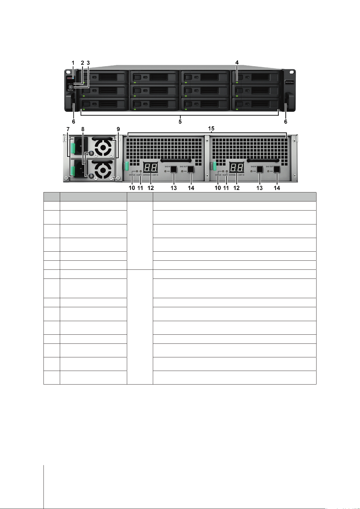
Synology RXD1219sas at a Glance
No. Article Name Location Description
Power Indicator
ALERT Indicator
Beep O Button
Front
Drive Status Indicators
Drive Tray Install drives (hard disk drives or solid state drives) here.
Rail Kit Release Tab Push in and hold to release the Synology server from the rail kit lock.
Power Port
PSU Indicator and
Beep O Button
PSU Fan Disposes of excess heat and cools the PSU.
STATUS Indicator
ALERT Indicator
Back
Expansion Unit ID Indicator Indicates the ID number of the expansion unit.
SAS IN Port and Indicator
SAS OUT Port and Indicator
SAS Module
10
11
12
13
14
15
1
2
3
4
5
6
7
8
9
Displays the power status.
Displays warnings regarding fan or temperature status. For more
information, please see "LED Indicator Table".
Press to deactivate the beeping sound that is emitted when a malfunction
occurs.
Displays the status of drives. For more information, please see "LED
Indicator Table".
Connect power cords here.
Displays the status of the power supply unit (PSU). Press to deactivate
the beeping sound that is emitted when a malfunction occurs. For more
information, please see "LED Indicator Table".
Displays the status of the system. For more information, please see "LED
Indicator Table".
Displays warnings regarding fan or temperature. For more information,
please see "LED Indicator Table".
Connects to the SAS OUT port of a Synology server or another expansion
unit. For more information, please see "Connect with Synology Server".
Connects to the SAS IN port of another expansion unit. For more
information, please see "Connect with Synology Server".
Connects to a Synology server or the SAS module of another expansion
unit. For more information, please see "Connect with Synology Server".
1
2
1
RXD1219sas automatically powers on when the power cord is plugged into the power source. For more information, please see "Connect with Synology
Server".
2
For more information about the rail kit installation, please refer to the Quick Installation Guide that comes with the rail kit.
4
Chapter 1: Before You Start
Page 5
Hardware Specication
Item RXD1219sas
Compatible Drive Type 3.5”/2.5” SAS x 12
Maximum Raw Capacity
Expansion Port (per module)
Size (H x W x D) (mm)
Weight (kg) 18.2
System Fan 4 x (60 x 60 x 51mm)
Agency Certication
Environment Requirements
Note: Model specications are subject to change without notice. Please refer to www.synology.com for the latest information.
• FCC Class A • CE Class A • BSMI Class A • VCCI Class A • RCM • EAC
• Operating Temperature: 32 to 95˚F (0 to 35˚C)
• Storage Temperature: -5 to 140˚F (-20 to 60˚C)
192TB (12 X 16TB HDD)
• SAS IN x 1
• SAS OUT x 1
• 88 x 430.5 x 692
• 88 x 482 x 724 (with server ears)
• Line voltage: 100V to 240V AC
• Frequency: 50 / 60Hz
• Relative Humidity: 5% to 95% RH
5
Chapter 1: Before You Start
Page 6
Optional Accessories
With Synology accessories, you can customize your expansion unit to t dierent business environments without
worrying about compatibility and stability. Visit
Rail Kit
•
Model Name Picture Description
RKS1317 Sliding rails solutions
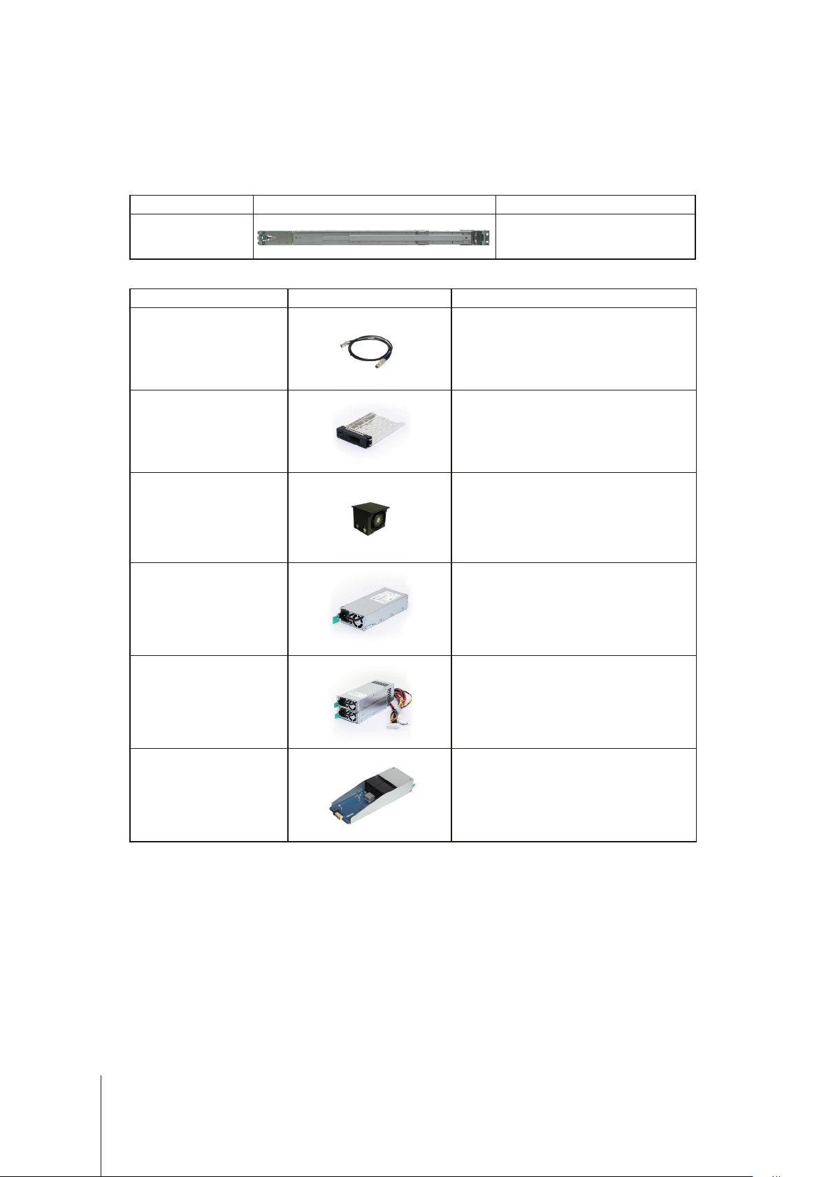
Spare Part
•
Model Name Picture Description
www.synology.com/compatibility
for more information.
Cable MiniSASHD_
EXT_1
Disk Tray (Type R7) 3.5"/2.5" Drive Tray
FAN 60*60*51_2 System Fan Module
PSU 500W-RP
Module_2
PSU 500W-RP SET_2
External MiniSAS HD Cable
Redundant PSU Module
Redundant PSU Set (Cage x 1, PSU
Module x 2)
RXD19sas Module RXD1219sas MB Module
6 Chapter 1: Before You Start
Page 7
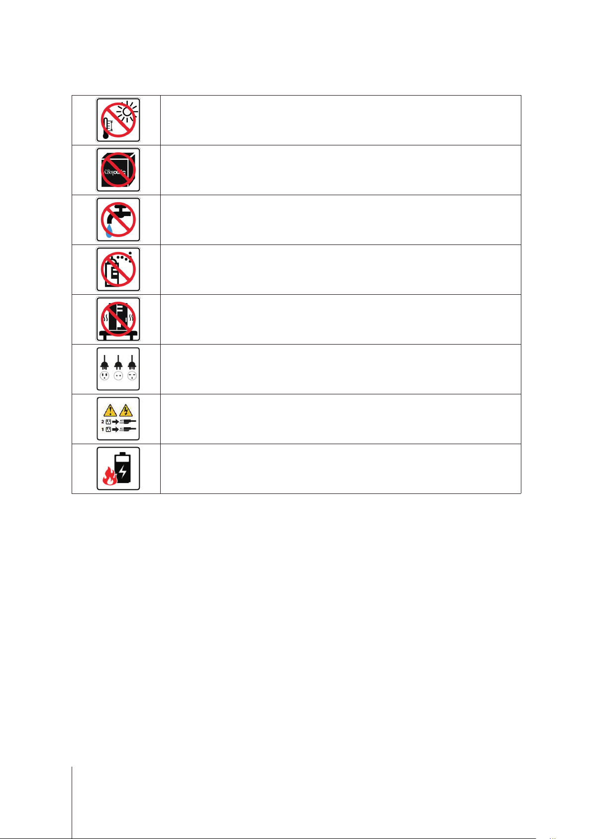
Safety Instructions
Keep away from direct sunlight and away from chemicals. Make sure the environment does not
experience abrupt changes in temperature or humidity.
Place the product right side up at all times.
Do not place near any liquids.
Before cleaning, unplug the power cord. Wipe with damp paper towels. Do not use chemical or
aerosol cleaners.
To prevent the unit from falling over, do not place on carts or any unstable surfaces.
The power cord must plug in to the correct supply voltage. Make sure that the supplied AC voltage is
correct and stable.
To remove all electrical current from the device, ensure that all power cords are disconnected from
the power source.
Risk of explosion if battery is replaced with an incorrect type. Dispose of used batteries appropriately.
7 Chapter 1: Before You Start
Page 8
Chapter
Hardware Setup
Tools and Parts for Component Installation
Please prepare the tools and parts below before setting up your expansion unit:
• A Screwdriver
• At least one 3.5” or 2.5” SAS drive (please visit
models).
Warning:
back up any important data before installation.
• Rail mounting kit (please see the
installation)
Warning:
will increase the installation diculty.
If you install a drive that contains data, the system will format the drive and erase all existing data. Please
Optional Accessories
We suggest mounting your expansion unit on a cabinet before installing any drives since the heavy weight
Install Drives
Please follow below steps for drive installation:
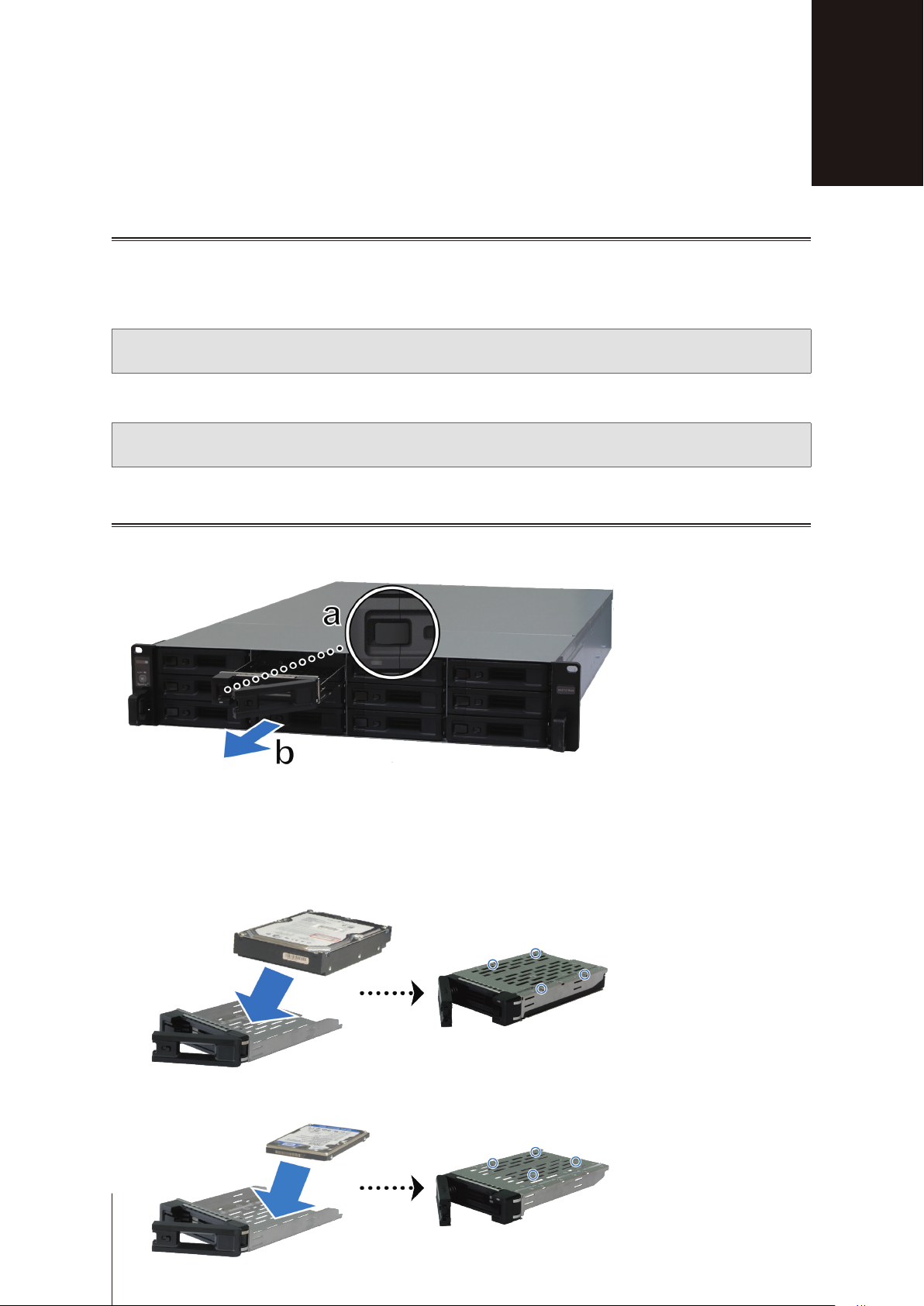
1
Open the drive tray.
www.synology.com/compatibility
section to nd out the suitable rail kit for cabinet
2
for compatible drive
8
a
Find the small button located on the left side of the drive tray handle. Press the button down, and the drive
tray handle will pop out.
b
Pull the drive tray handle out as illustrated above.
2
Install drives:
For 3.5” drives:
•
spots indicated below to secure the drive.
For 2.5” drives:
•
spots indicated below to secure the drive.
Place the drive in the drive tray. Turn the tray upside down and tighten screws into the four
Place the drive in the drive tray. Turn the tray upside down and tighten screws into the four
Page 9

3
Insert the loaded drive tray into the empty drive bay.
Note:
Make sure the tray is pushed in all the way. Otherwise, the drive might not be able to function properly.
4
Push the handle inward to secure the drive tray.
5
Push the switch on the drive tray handle to the left to lock the drive tray.
6
Repeat the steps above to assemble the other drives you have prepared.
7
Drives are numbered as shown below.
Note:
We suggest installing drives of the same size to optimize drive capacity usage when creating RAID volumes.
9 Chapter 2: Hardware Setup
Page 10

Install and Remove Rail Kits
Here we use RKS1317 as an example to illustrate how to install or remove the rail kits. For more information
about the rail kit installation, please refer to the Quick Installation Guide that comes with the rail kit.
To install the rail kit:
1
To install the rail kit to the rack
a
Attach the rear end of the rail kit assembly to the rack.
b
Slide the front latch outwards and insert the brackets into the rack holes.
2
Extend and pull out the inner rail from the assembly.
10 Chapter 2: Hardware Setup
Page 11

3
Align the xing holes of the inner rail to the side of the chassis and slide backward to attach the inner rail.
4
With the help of another person, carefully align the inner rail to the outer rail assembly.
5
Push the chassis towards the rack. Use the cage nuts and screws in the rail kit package to secure the chassis
to the rack if necessary.
11 Chapter 2: Hardware Setup
Page 12

To remove the rail kit:
1
To remove the chassis from the rack, hold the rail kit release tabs on the ear holders and pull out the chassis
from the rack.
2
With the help of another person, carefully remove the chassis from the rack. Then, slide forwards to remove
the inner rail from the chassis.
12 Chapter 2: Hardware Setup
Page 13

Connect with Synology Server
1
Connect one end of mini-SAS HD cable to the SAS port of your Synology server and the other to the SAS
IN port of RXD1219sas. Please make sure that the release band (in blue) of the cable faces rightward when
plugging into the Synology server, and that of the cable faces upward when plugging into RXD1219sas;
otherwise, your Synology server and expansion unit will not be correctly connected.
2
Connect one end of mini-SAS HD cable to the SAS OUT port on SAS module A of an expansion unit (e.g.,
module A1), and the other end to the SAS IN port on SAS module A of the next expansion unit (e.g., module
A2).
3
Connect one end of mini-SAS HD cable to the SAS OUT port on SAS module B of an expansion unit (e.g.,
module B1), and the other end to the SAS IN port on SAS module B of the next expansion unit (e.g., module
B2).
13 Chapter 2: Hardware Setup
Page 14

4
Connect one end of the power cord(s) to the power port of RXD1219sas, and the other to the power outlet(s).
RXD1219sas will automatically power on once the power cords are correctly connected.
Note:
1. Your RXD1219sas comes equipped with a redundant power supply system, allowing two power cords to be
connected. The system may be powered on with only one power cord, but we recommend using two power cords
to avoid unexpected power failures.
2. After you have unplugged the power cord, please make sure all the indicator is o before plugging the power
cord back in again; otherwise, the system may fail to boot.
Important:
loss.
5
Press the power button on the front panel to power on your Synology server. The expansion unit ID of
Do not remove the expansion cable while the host device is still powered on. Doing so may result in data
RXD1219sas connected to Synology server will be displayed in sequence on the back panel.
14 Chapter 2: Hardware Setup
Page 15

LED Indicator Table
LED Indicator Color Status Description
Power
Front ALERT
Rear ALERT
Rear STATUS
Drive Status Indicator
(on tray)
PSU Indicator
SAS IN / OUT
Blue Static Powered on
O Powered o
Orange Blinking Fan failure / Over temperature
O System normal
Orange Blinking Fan failure / Over temperature
O System normal
Green Blinking Powered on
O Powered o
Static Drive ready and idle
Green
Blinking Accessing drive
Red Static Drive error / Port disabled
1
O No internal drive
Green Static Power supply unit normal
O Power supply unit o
Green Static Synology server / expansion unit connected
O Synology server / expansion unit disconnected
Note:
Model specications are subject to change without notice. Please refer to
1
Please try to restart your Synology server or re-insert the drive(s), and then run the HDD/SSD manufacturer's diagnostic tool to check the health status of
the drive(s). If you can log into DSM, please run the built-in S.M.A.R.T. test to scan the drive(s). If the problem remains unresolved, please contact Synology
Technical Support for help.
www.synology.com
for the latest information.
15 Chapter 2: Hardware Setup
Page 16

Chapter
System Maintenance
Replace SAS Module
If a SAS module malfunctions, please see the instructions below to pull out the SAS module and replace the
malfunctioning module.
To replace the malfunctioning SAS module:
1
Unplug the expansion cables from the SAS module on which the malfunctioning module is to be replaced.
2
Push the lever of the SAS module at the back panel in the indicated direction. The modules are numbered as
shown below.
3
Pull out the SAS module from the expansion unit.
3
4
Prepare a new SAS module, and push it back to the slot until you hear a click.
16 Chapter 3: System Maintenance
Page 17

To replace the SAS module's malfunctioning fan:
1
Remove the malfunctioning fan by pulling it up from the module. The fans are numbered as shown below.
2
Prepare a new fan, align the arrow to point at the back panel as illustrated below, and insert it back into the fan
slot.
3
Push the module back to the expansion unit until you hear a click.
17 Chapter 3: System Maintenance
Page 18

Replace Power Supply Unit (PSU)
If a PSU or its fan malfunctions, please see the instructions below to replace the malfunctioning PSU.
1
Unplug the power cord from the PSU to be replaced.
Note:
By pressing the
2
Push the lever of the PSU at the back panel in the indicated direction.
3
Pull out the PSU from your RXD1219sas.
4
Prepare a new PSU, and push it back to the slot until you hear a click.
Beep O
button, you can silence the long beeping sound when you hear it.
Initial Troubleshooting Guide
We have selected several helpful articles on frequently asked questions to help you do initial troubleshooting on
your Synology server:
• General
What can I do to troubleshoot NAS connection problems?
•
What is the width of my Synology NAS server?
•
• Hard Disk Drive
How to choose the right HDD for my Synology NAS
•
How to diagnose drives' health status when receiving bad sector warning
•
How to x hard drive failure and retrieve the data from your hard drives
•
• Memory
Are there any requirements for installing or expanding system memory capacity?
•
How can I run a memory test on my Synology NAS?
•
Why is there a startup delay after a memory upgrade?
•
• LED
How do I recognize a hibernating Synology NAS via the LED indicators?
•
What can I do if the STATUS LED keeps ashing in orange?
•
Why am I unable to install my Synology NAS and why is the Power LED indicator ashing
•
constantly?
Why are the LED indicators on the LAN ports of my Synology NAS not working?
•
• Fan
What type of fan speed modes are available on my Synology NAS?
•
18 Chapter 3: System Maintenance
Page 19

SYNOLOGY, INC.
END USER LICENSE AGREEMENT
IMPORTANT–READ CAREFULLY: THIS END USER LICENSE AGREEMENT ("EULA") IS A LEGAL AGREEMENT
BETWEEN YOU (EITHER AN INDIVIDUAL OR A LEGAL ENTITY) AND SYNOLOGY, INC. ("SYNOLOGY") FOR THE
SYNOLOGY SOFTWARE INSTALLED ONTO THE SYNOLOGY PRODUCT PURCHASED BY YOU (THE "PRODUCT"),
OR LEGALLY DOWNLOADED FROM WWW.SYNOLOGY.COM, OR ANY OTHER CHANNEL PROVIDED BY
SYNOLOGY ( "SOFTWARE").
YOU AGREE TO BE BOUND BY THE TERMS OF THIS EULA BY USING THE PRODUCTS CONTAINING THE
SOFTWARE, INSTALLING THE SOFTWARE ONTO THE PRODUCTS OR DEVICE CONNECTED TO THE PRODUCTS.
IF YOU DO NOT AGREE TO THE TERMS OF THIS EULA, DO NOT USETHE PRODUCTS CONTAINING THE
SOFTWAREOR DOWNLOAD THE SOFTWARE FROM WWW.SYNOLOGY.COM, OR ANY OTHER CHANNEL
PROVIDED BY SYNOLOGY.INSTEAD, YOU MAY RETURN THE PRODUCT TO THE RESELLER WHERE YOU
PURCHASED IT FOR A REFUND IN ACCORDANCE WITH THE RESELLER'S APPLICABLE RETURN POLICY.
Section 1. Limited Software License. Subject to the terms and conditions of this EULA, Synology grants you a limited, nonexclusive, non-transferable, personal license to install, run and use one copy of the Software loaded on the Product or on
your device connected to the Product solely relating to your authorized use of the Product.
Section 2. Documentation. You may make and use a reasonable number of copies of any documentation provided with the
Software; provided that such copies will only be used for internal business purposes and are not to be republished or
redistributed (either in hard copy or electronic form) to any third party.
Section 3. Backup. You may make a reasonable number of copies of the Software for backup and archival purposes only.
Section 4. Updates. Any software provided to you by Synology or made available on the Synology website at
www.synology.com ("Website") or any other channel provided by Synology that updates or supplements the original
Software is governed by this EULA unless separate license terms are provided with such updates or supplements, in which
case, such separate terms will govern.
Section 5. License Limitations. The license set forth in Sections 1, 2 and 3 applies only to the extent that you have ordered
and paid for the Product and states the entirety of your rights with respect to the Software. Synology reserves all rights not
expressly granted to you in this EULA. Without limiting the foregoing, you shall not authorize or permit any third party to: (a)
use the Software for any purpose other than that in connection with the Product; (b) license, distribute, lease, rent, lend,
transfer, assign or otherwise dispose of the Software; (c) reverse engineer, decompile, disassemble or attempt to discover
the source code of or any trade secrets related to the Software, except and only to the extent that such conduct is
expressly permitted by applicable law notwithstanding this limitation; (d) adapt, modify, alter, translate or create any
derivative works of the Software; (e) remove, alter or obscure any copyright notice or other proprietary rights notice on the
Software or Product; or (f) circumvent or attempt to circumvent any methods employed by Synology to control access to the
components, features or functions of the Product or Software. Subject to the limitations specified in this Section 5, you are
not prohibited from providing any services hosted by Synology NAS server to any third party for commercial purpose.
Section 6. Open Source. The Software may contain components licensed to Synology under the GNU General Public
License ("GPL Components"), currently available at http://www.gnu.org/licenses/gpl.html. The terms of the GPL will control
solely with respect to the GPL Components to the extent that this EULA conflicts with the requirements of the GPL with
respect to your use of the GPL Components, and, in such event, you agree to be bound by the GPL with respect to your
use of such components.
Section 7. Audit. Synology will have the right to audit your compliance with the terms of this EULA. You agree to grant
Synology a right to access to your facilities, equipment, books, records and documents and to otherwise reasonably
cooperate with Synology in order to facilitate any such audit by Synology or its agent authorized by Synology.
Section 8. Ownership. The Software is a valuable property of Synology and its licensors, protected by copyright and other
intellectual property laws and treaties. Synology or its licensors own all rights, titles and interests in and to the Software,
including but not limited to copyright and any other intellectual property rights.
Section 9. Limited Warranty. Synology provides a limited warrant that the Software will substantially conform to Synology's
published specifications for the Software, if any, or otherwise set forth on the Website, for a period required by your local
law. Synology will use commercially reasonable efforts to, in Synology's sole discretion, either correct any such
nonconformity in the Software or replace any Software that fails to comply with the foregoing warranty, provided that you
give Synology written notice of such noncompliance within the warranty period. The foregoing warranty does not apply to
any noncompliance resulting from any: (w) use, reproduction, distribution or disclosure not in accordance with this EULA;
(x) any customization, modification or other alteration of the Software by anyone other than Synology; (y) combination of
the Software with any product, services or other items provided by anyone other than Synology; or (z) your failure to
comply with this EULA.
Section 10. Support. During the period specified in the Section 9, Synology will make available to you the support services.
Following the expiration of the applicable period, support for Software may be available from Synology upon written
Page 20

request.
Section 11. Disclaimer of Warranties. EXCEPT AS EXPRESSLY SET FORTH ABOVE, THE SOFTWARE IS PROVIDED
"AS IS" AND WITH ALL FAULTS. SYNOLOGY AND ITS SUPPLIERS HEREBY DISCLAIM ALL OTHER WARRANTIES,
EXPRESS, IMPLIED OR STATUTORY, ARISING BY LAW OR OTHERWISE, INCLUDING BUT NOT LIMITED TO ANY
IMPLIED WARRANTIES OF MERCHANTABILITY, FITNESS FOR A PARTICULAR PURPOSE OR USE, TITLE AND
NONINFRINGEMENT, WITH REGARD TO THE SOFTWARE. WITHOUT LIMITING THE FOREGOING, SYNOLOGY
DOES NOT WARRANT THAT THE SOFTWARE WILL BE FREE OF BUGS, ERRORS, VIRUSES OR OTHER DEFECTS.
Section 12. Disclaimer of Certain Damages. IN NO EVENT WILL SYNOLOGY OR ITS LICENSORS BE LIABLE FOR ANY
INCIDENTAL, INDIRECT, SPECIAL, PUNITIVE, CONSEQUENTIAL OR SIMILAR DAMAGES OR LIABILITIES
WHATSOEVER (INCLUDING, BUT NOT LIMITED TO LOSS OF DATA, INFORMATION, REVENUE, PROFIT OR
BUSINESS) ARISING OUT OF OR RELATING TO THE USE OF OR INABILITY TO USE THE SOFTWARE OR
OTHERWISE UNDER OR IN CONNECTION WITH THIS EULA OR THE SOFTWARE, WHETHER BASED ON
CONTRACT, TORT (INCLUDING NEGLIGENCE), STRICT LIABILITY OR OTHER THEORY EVEN IF SYNOLOGY HAS
BEEN ADVISED OF THE POSSIBILITY OF SUCH DAMAGES.
Section 13. Limitation of Liability. SYNOLOGY'S AND ITS SUPPLIERS' LIABILITY ARISING OUT OF OR RELATING TO
THE USE OF OR INABILITY TO USE THE SOFTWARE OR OTHERWISE UNDER OR IN CONNECTION WITH THIS
EULA OR THE SOFTWARE IS LIMITED TO THE AMOUNT ACTUALLY PAID BY YOU FOR THE PRODUCT
REGARDLESS OF THE AMOUNT OF DAMAGES YOU MAY INCUR AND WHETHER BASED ON CONTRACT, TORT
(INCLUDING NEGLIGENCE), STRICT LIABILITY OR OTHER THEORY. The foregoing disclaimer of warranties,
disclaimer of certain damages and limitation of liability will apply to the maximum extent permitted by applicable law. The
laws of some states/jurisdictions do not allow the exclusion of implied warranties or the exclusion or limitation of certain
damages. To the extent that those laws apply to this EULA, the exclusions and limitations set forth above may not apply to
you.
Section 14. Export Restrictions. You acknowledge that the Software is subject to U.S. export restrictions. You agree to
comply with all applicable laws and regulations that apply to the Software, including without limitation the U.S. Export
Administration Regulations.
Section 15. Termination. Without prejudice to any other rights, Synology may terminate this EULA if you do not abide by
the terms and conditions contained herein. In such event, you must cease use of the Software and destroy all copies of the
Software and all of its component parts.
Section 16. Assignment. You may not transfer or assign your rights under this EULA to any third party, except for that preinstalled in the Products. Any such transfer or assignment in violation of the foregoing restriction will be void.
Section 17. Applicable Law. Unless expressly prohibited by local law, this EULA is governed by and construed in
accordance with the laws of the country, in accordance with which Synology Inc. was organized without regard to any
conflict of law principles to the contrary.
Section 18. Dispute Resolution. Any dispute, controversy or claim arising out of or relating to this EULA will be resolved
exclusively and finally by arbitration conducted by three neutral arbitrators in accordance with the procedures of the
Arbitration Law and related enforcement rules of the country in which Synology Inc. was organized. In such cases, the
arbitration will be limited solely to the dispute between you and Synology. The arbitration, or any portion of it, will not be
consolidated with any other arbitration and will not be conducted on a class-wide or class action basis. The arbitration shall
take place in Taipei and the arbitration proceedings shall be conducted in English or, if both parties so agree, in Mandarin
Chinese. The arbitration award shall be final and binding on the parties and may be enforced in any court having
jurisdiction. You understand that, in the absence of this provision, you would have had a right to litigate any such dispute,
controversy or claim in a court, including the right to litigate claims on a class-wide or class-action basis, and you expressly
and knowingly waive those rights and agree to resolve any disputes through binding arbitration in accordance with the
provisions of this Section 18. Nothing in this Section shall be deemed to prohibit or restrict Synology from seeking injunctive
relief or seeking such other rights and remedies as it may have at law or equity for any actual or threatened breach of any
provision of this EULA relating to Synology's intellectual property rights.
Section 19. Attorneys' Fees. In any arbitration, mediation, or other legal action or proceeding to enforce rights or remedies
under this EULA, the prevailing party will be entitled to recover, in addition to any other relief to which it may be entitled,
costs and reasonable attorneys' fees.
Powered by TCPDF (www.tcpdf.org)
Section 20. Severability. If any provision of this EULA is held by a court of competent jurisdiction to be invalid, illegal, or
unenforceable, the remainder of this EULA will remain in full force and effect.
Section 21. Entire Agreement. This EULA sets forth the entire agreement of Synology and you with respect to the Software
and the subject matter hereof and supersedes all prior and contemporaneous understandings and agreements whether
written or oral. No amendment, modification or waiver of any of the provisions of this EULA will be valid unless set forth in a
written instrument signed by the party to be bound thereby.
Page 21

SYNOLOGY, INC.LIMITED PRODUCT WARRANTY
THIS LIMITED WARRANTY ("WARRANTY") APPLIES TO THE PRODUCTS (AS DEFINED BELOW) OF SYNOLOGY, INC.
AND ITS AFFILIATES, INCLUDING SYNOLOGY AMERICA CORP, (COLLECTIVELY, "SYNOLOGY"). YOU ACCEPT AND
AGREE TO BE BOUND BY THE TERMS OF THIS WARRANTY BY OPENING THE PACKAGE CONTAINING AND/OR
USING THE PRODUCT. PLEASE BE ADVISED THAT THIS LIMITED WARRANTY DOES NOT APPLY TO THE SOFTWARE
CONTAINED IN THE PRODUCTS WHICH SHALL BE SUBJECT TO ITS END USER LICENSE AGREEMENT, AND THAT
SYNOLOGY RESERVES THE RIGHT TO MAKE ADJUSTMENTS AND/OR MODIFICATION TO THIS PRODUCT
WARRANTY FROM TIME TO TIME WITHOUT PROVIDING PRIOR NOTICE TO YOU. IF YOU DO NOT AGREE TO THE
TERMS OF THIS WARRANTY, DO NOT USE THE PRODUCT. INSTEAD, YOU MAY RETURN THE PRODUCT TO THE
RESELLER WHERE YOU PURCHASED IT FOR A REFUND IN ACCORDANCE WITH THE RESELLER'S APPLICABLE
RETURN POLICY.PLEASE NOTE THAT SYNOLOGY’S WARRANTY SUPPORTS ARE NOT AVAILABLE IN EVERY
COUNTRY, AND THAT SYNOLOGY MAY REFUSE TO PROVIDE THIS LIMITED WARRANTY SUPPORTS TO YOU IF YOU
REQUEST SUCH SUPPORTS NOT AT THE COUNTRY AT WHICH THE PRODUCT WAS ORIGINALLY PURCHASED. THE
COUNTRY AT WHICH THE PRODUCT WAS ORIGINALLY PURCHASED SHALL BE DETERMINED BASED ON THE
SYNOLOGY’S INTERNAL RECORDS.
Section 1. Products
(a) "Products" refer to New Products or Refurbished Products.(b) "New Product" means the Synology-branded hardware
product and Synology-branded accessories contained in the original packaging Customer bought from an authorized Synology
distributor or reseller. You may see our “New Product” at https://www.synology.com/products/status.(c) "Refurbished Product"
means all Synology products which have been refurbished by Synology’s affiliate or an authorized Synology distributor or
reseller, not including those sold as "as is" or with "no warranty" by anyone.(d) Other definition: "Customer" means the original
person or entity purchasing the Product from Synology or an authorized Synology distributor or reseller; "Online Store" means
an online shop operated by Synology or Synology’s affiliate; "Software" means the Synology proprietary software that
accompanies the Product when purchased by Customer, is downloaded by Customer from the Web Site, or is pre-installed on
the Product by Synology, and includes any firmware, associated media, images, animations, video, audio, text and applets
incorporated into the software or Product and any updates or upgrades to such software.
Section 2. Warranty Period
(a) "Warranty Period": The warranty period commences on the purchase date is shown on the purchase receipt or invoice to be
presented by Customer and ending at the day after the end of the Warranty Period for each New Product. You may see the
Warranty Period for each New Product at https://www.synology.com/products/status. For the Refurbished Product or repaired
parts, it's the remainder of the warranty period of the product they are replacing, or ninety (90) days from the date the product
was replaced or repaired, whichever is longer; except for those sold as "as is" or with "no warranty" by any stores. Without
presenting such purchase receipt or invoice, the warranty period shall commence on the date of manufacture based on our
internal record.(b) "Extended Warranty Period": For Customer purchasing EW201/ EW202 optional service for applicable
Products specified in Section 1 (b), the Warranty Period specified in Section 2 (a) of the applicable Product registered with
EW201/EW202 optional service will be extended by two years. You may see the applied model at
https://www.synology.com/products/Extended_Warranty.
Section 3. Limited Warranty and Remedies
3.1 Limited Warranty. Subject to Section 3.2, Synology warrants to the Customer that each Product (a) will be free of material
defects in workmanship and (b) under normal use will perform substantially in accordance with Synology's published
specifications for the Product during the Warranty Period. Such limited warranty does not apply to the Software contained in
the product or purchased by Customer which shall be subject to the accompanying end user license agreement provided with
the Product. Synology provides no warranty to Refurbished Product sold as "as is" or with "no warranty". This Limited Warranty
is NOT transferable and applies only to the customers who directly purchase products from Synology’s affiliate, the resellers,
and distributor that Synology authorized. The warranty set forth in Section 3 will terminate upon Customer's sale or transfer of
the Product to a third party.
3.2 Exclusions. The foregoing warranties and warranty obligations do not apply to any Product that (a) has been installed or
used in a manner not specified or described in the Product or its related documents (b) has been damaged by service
(including upgrades and expansions) performed by anyone who is not a representative of Synology or any Synology
Authorized Service Provider; (c) has been in any way misused, abused, or damaged; (d) has been used with items not
provided by Synology other than the hardware or software for which the Product is designed; or (e) otherwise fails to conform
to the Product specifications and such failure is attributable to causes not within or under Synology's control. (f) has been tie-in
any non-Synology branded hardware products or any software, even if packaged or sold with Synology hardware. (g)
Customer disassembles the Product except as authorized by Synology; (h) Customer fails to implement any correction,
modification, enhancement, improvement or other update made available to Customer by Synology; or (i) Customer
implements, installs or uses any correction, modification, enhancement, improvement or other update made available by any
third party. (j) Any compatibility issues occurred when installing hardware products, software, or components not supported by
Synology. (k) product damage caused by accident, fire, liquid contact, earthquake or other external cause. (l) cosmetic damage
caused by normal wear and tear or otherwise due to the normal aging of the Product, including but not limited to scratches,
dents and broken plastic on ports unless failure has occurred due to a defect in materials or workmanship; (m) serial number
has been removed or defaced from Product, resulting in not able to identify.
Page 22

3.3 Warranty Support and Exclusive Remedy. If Customer gives notice of noncompliance with any of the warranties set forth
in Section 3.1 within the applicable Warranty Period in the manner set forth below, then, upon verification of the noncompliance
by Synology, Synology will, at Synology's option: (a) use commercially reasonable efforts to repair the Product, (b) provide
technical support, or (c) replace the noncomplying Product or part thereof upon return of the complete Product in accordance
with Section 3.4 The foregoing sets forth Synology's entire liability and Customer's sole and exclusive remedy for any breach of
warranty under Section 3.1 or any other defect or deficiency in the Product. Customer will reasonably assist Synology to
diagnose and validate any nonconformity with the Product.
3.4 Return. Any Product return by Customer under Section 3.3 must be made in accordance with Synology's then-current
return procedures with the purchase receipt or invoice. You may see more information about return procedure at
https://www.synology.com/knowledgebase/DSM/tutorial/Service_Application/How_to
_make_warranty_claim_for_Synology_NAS, for warranty claims, Customer must return the complete Product to Synology in
accordance with this Section 3.4. Any Product returned that has been disassembled (except under the direction of Synology)
will be refused and returned to Customer at Customer's expense. Any Product must be returned in the same condition as it
was received from Synology to the address designated by Synology, freight pre-paid, in packaging sufficient to protect the
contents thereof. Customer is responsible for insurance and risk of loss with respect to returned items until they are properly
received by Synology.
3.5 Replacement by Synology. If Synology elects to replace any Product under this Warranty set forth in Section 3.1, then
Synology will ship a replacement Product at Synology's expense via the shipping method selected by Synology after receipt of
the nonconforming Product returned in accordance with Section 3.4 and validation by Synology that the Product does not
conform to the warranty. In some countries, Synology may at its own discretion apply the Synology Replacement Service to
certain Products, through which Synology will ship a replacement Product to Customer before its receipt of the nonconforming
Product returned by Customer ("Synology Replacement Service").
3.6 Disclaimer of Warranties. THE WARRANTIES, OBLIGATIONS, AND LIABILITIES OF SYNOLOGY AND THE
REMEDIES OF CUSTOMER SET FORTH IN THIS WARRANTY ARE EXCLUSIVE AND IN SUBSTITUTION FOR, AND
CUSTOMER HEREBY WAIVES, RELEASES AND DISCLAIMS, ALL OTHER WARRANTIES, OBLIGATIONS AND
LIABILITIES OF SYNOLOGY AND ALL OTHER RIGHTS, CLAIMS AND REMEDIES OF CUSTOMER AGAINST SYNOLOGY,
EXPRESS OR IMPLIED, ARISING BY LAW OR OTHERWISE, WITH RESPECT TO THE PRODUCT, ACCOMPANYING
DOCUMENTATION OR SOFTWARE AND ANY OTHER GOODS OR SERVICES DELIVERED UNDER THIS WARRANTY,
INCLUDING, BUT NOT LIMITED TO ANY: (A) IMPLIED WARRANTY OF MERCHANTABILITY OR FITNESS FOR A
PARTICULAR PURPOSE OR USE; (B) IMPLIED WARRANTY ARISING FROM COURSE OF PERFORMANCE, COURSE OF
DEALING, OR USAGE OF TRADE; (C) CLAIM OF INFRINGEMENT OR MISAPPROPRIATION; OR (D) CLAIM IN TORT
(WHETHER BASED ON NEGLIGENCE, STRICT LIABILITY, PRODUCT LIABILITY OR OTHER THEORY). SYNOLOGY
MAKES NO GUARANTEE AND SPECIFICALLY DISCLAIMS ANY WARRANTY THAT THE DATA OR INFORMATION
STORED ON ANY SYNOLOGY PRODUCT WILL BE SECURE AND WITHOUT RISK OF DATA LOSS. SYNOLOGY
RECOMMENDS THAT CUSTOMER TAKES APPROPRIATE MEASURES TO BACK UP THE DATA STORED ON THE
PRODUCT. SOME STATES/JURISDICTIONS DO NOT ALLOW LIMITATIONS ON IMPLIED WARRANTIES, SO THE ABOVE
LIMITATION MAY NOT APPLY TO CUSTOMER.
Section 4. Limitations of Liability
4.1 Force Majeure. Synology will not be liable for, or be considered to be in breach of or default under this Warranty on
account of, any delay or failure to perform as required by this Warranty as a result of any cause or condition beyond its
reasonable control (including, without limitation, any act or failure to act by Customer).
4.2 Disclaimer of Certain Damages. IN NO EVENT WILL SYNOLOGY OR ITS SUPPLIERS BE LIABLE FOR THE COST OF
COVER OR FOR ANY INCIDENTAL, INDIRECT, SPECIAL, PUNITIVE, CONSEQUENTIAL OR SIMILAR DAMAGES OR
LIABILITIES WHATSOEVER (INCLUDING, BUT NOT LIMITED TO LOSS OF DATA, INFORMATION, REVENUE, PROFIT
OR BUSINESS) ARISING OUT OF OR RELATING TO THE USE OR INABILITY TO USE THE PRODUCT, ANY
ACCOMPANYING DOCUMENTATION OR SOFTWARE AND ANY OTHER GOODS OR SERVICES PROVIDED UNDER
THIS WARRANTY, WHETHER BASED ON CONTRACT, TORT (INCLUDING NEGLIGENCE), STRICT LIABILITY OR
OTHER THEORY EVEN IF SYNOLOGY HAS BEEN ADVISED OF THE POSSIBILITY OF SUCH DAMAGES.
4.3 Limitation of Liability. SYNOLOGY'S AND ITS SUPPLIERS' LIABILITY ARISING OUT OF OR RELATING TO THE USE
OR INABILITY TO USE THE PRODUCT, ANY ACCOMPANYING DOCUMENTATION OR SOFTWARE AND ANY OTHER
GOODS OR SERVICES PROVIDED UNDER THIS WARRANTY IS LIMITED TO THE AMOUNT ACTUALLY PAID BY
CUSTOMER FOR THE PRODUCT REGARDLESS OF THE AMOUNT OF DAMAGES CUSTOMER MAY INCUR AND
WHETHER BASED ON CONTRACT, TORT (INCLUDING NEGLIGENCE), STRICT LIABILITY OR OTHER THEORY. The
foregoing disclaimer of certain damages and limitation of liability will apply to the maximum extent permitted by applicable law.
The laws of some states/jurisdictions do not allow exclusion or limitation of certain damages. To the extent that those laws
apply to the Product, the exclusions and limitations set forth above may not apply to Customer.
Section 5. Miscellaneous
5.1 Proprietary Rights. The Product and any accompanying Software and documentation provided with the Product include
proprietary and intellectual property rights of Synology and its third party suppliers and licensors. Synology retains and
reserves all right, title, and interest in the intellectual property rights of the Product, and no title to or ownership of any
intellectual property rights in or to the Product, any accompanying Software or documentation and any other goods provided
under this Warranty is transferred to Customer under this Warranty. Customer will (a) comply with the terms and conditions of
Page 23

the Synology end user license agreement accompanying any Software furnished by Synology or an authorized Synology
distributor or reseller; and (b) not attempt to reverse engineer any Product or component thereof or accompanying Software or
otherwise misappropriate, circumvent or violate any of Synology's intellectual property rights.
5.2 Assignment. Customer will not assign any of its rights under this Warranty directly, by operation of law or otherwise,
without the prior written consent of Synology.
5.3 No Additional Terms. Except as expressly permitted by this Warranty, neither party will be bound by, and each party
specifically objects to, any term, condition or other provision that conflicts with the provisions of this Warranty that is made by
the other party in any purchase order, receipt, acceptance, confirmation, correspondence or otherwise, unless each party
specifically agrees to such provision in writing. Further, if this Warranty conflicts with any terms or conditions of any other
agreement entered into by the parties with respect to the Product, this Warranty will prevail unless the other agreement
specifically references the sections of this Warranty that it supersedes.
5.4 Applicable Law. Unless explicitly prohibited by local law, this Warranty is governed by the laws of the State of
Washington, U.S.A. for the Customers residing within the United States; and by the laws of the Republic of China (Taiwan) for
Customers not residing within the United States, without regard to any conflict of law principles to the contrary. The 1980 U.N.
Convention on Contracts for the International Sale of Goods or any successor thereto does not apply.
5.5 Dispute Resolution. Any dispute, controversy or claim arising out of or relating to this Warranty, the Product or services
provided by Synology with respect to the Product or the relationship between Customers residing within the United States and
Synology will be resolved exclusively and finally by arbitration under the current commercial rules of the American Arbitration
Association, except as otherwise provided below. The arbitration will be conducted before a single arbitrator, and will be limited
solely to the dispute between Customer and Synology. The arbitration, or any portion of it, will not be consolidated with any
other arbitration and will not be conducted on a class-wide or class action basis. The arbitration shall be held in King County,
Washington, U.S.A. by submission of documents, by telephone, online or in person as determined by the arbitrator at the
request of the parties. The prevailing party in any arbitration or legal action occurring within the United States or otherwise shall
receive all costs and reasonable attorneys’ fees, including any arbitration fee paid by the prevailing party. Any decision
rendered in such arbitration proceedings will be final and binding on the parties, and judgment may be entered thereon in any
court of competent jurisdiction. Customer understands that, in the absence of this provision, Customer would have had a right
to litigate any such dispute, controversy or claim in a court, including the right to litigate claims on a class-wide or class-action
basis, and Customer expressly and knowingly waives those rights and agrees to resolve any disputes through binding
arbitration in accordance with the provisions of this Section 5.5. For Customers not residing within the United States, any
dispute, controversy or claim described in this section shall be finally resolved by arbitration conducted by three neutral
arbitrators in accordance with the procedures of the R.O.C. Arbitration Law and related enforcement rules. The arbitration shall
take place in Taipei, Taiwan, R.O.C., and the arbitration proceedings shall be conducted in English or, if both parties so agree,
in Mandarin Chinese. The arbitration award shall be final and binding on the parties and may be enforced in any court having
jurisdiction. Nothing in this Section shall be deemed to prohibit or restrict Synology from seeking injunctive relief or seeking
such other rights and remedies as it may have at law or equity for any actual or threatened breach of any provision of this
Warranty relating to Synology's intellectual property rights.
5.6 Attorneys' Fees. In any arbitration, mediation, or other legal action or proceeding to enforce rights or remedies under this
Warranty, the prevailing party will be entitled to recover, in addition to any other relief to which it may be entitled, costs and
reasonable attorneys' fees.
5.7 Export Restrictions. You acknowledge that the Product may be subject to U.S. export restrictions. You will comply with all
applicable laws and regulations that apply to the Product, including without limitation the U.S. Export Administration
Regulations.
5.8 Severability. If any provision of this Warranty is held by a court of competent jurisdiction to be invalid, illegal, or
unenforceable, the remainder of this Warranty will remain in full force and effect.
5.9 Entire Agreement. This Warranty constitutes the entire agreement, and supersedes any and all prior agreements,
between Synology and Customer related to the subject matter hereof. No amendment, modification or waiver of any of the
provisions of this Warranty will be valid unless set forth in a written instrument signed by the party to be bound thereby.
Page 24

FCC Declaration of Conformity
This device complies with Part 15 of the FCC Rules. Operation is subject to the following
two conditions: (1) this device may not cause harmful interference, and (2) this device must accept
any interference received, including interference that may cause undesired operation.
Page 25

この装置は、クラス A 機器です。この装置を住宅環境で使用すると電波妨
害を引き起こすことがあります。この場合には使用者が適切な対策を講ずる
よう要求されることがあります。 VCCI 一 A
 Loading...