

Page 1

Synology RackStation RS3617xs
Quick Installation Guide
Page 2

Table of Contents
Chapter 1: Before You Start
Package Contents 3
Synology RackStation at a Glance 4
Safety Instructions 5
Chapter 2: Hardware Setup
Tools and Parts for Drive Installation 6
Install Drives 6
Add a RAM Module on RackStation 8
Add a Network Interface Card to RackStation 11
Replace System Fan 13
Start Up Your RackStation 15
Chapter 3: Install DSM on RackStation
Install DSM with Web Assistant 17
Learn More 17
Appedix A: Specications
Appedix B: LED Indicator Table
Synology_QIG_RS3617xs_20160321
2
Page 3

Chapter
Before You Start
Thank you for purchasing this Synology product! Before setting up your new RackStation, please check the
package contents to verify that you have received the items below. Also, make sure to read the safety instructions
carefully to avoid harming yourself or damaging your RackStation.
Note:
All images below are for illustrative purposes only, and may differ from the actual product.
Package Contents
Main unit x 1 AC power cord x 1
Screws for 2.5” drives x 52
1
Screws for 3.5” drives x 52
3
3
Page 4
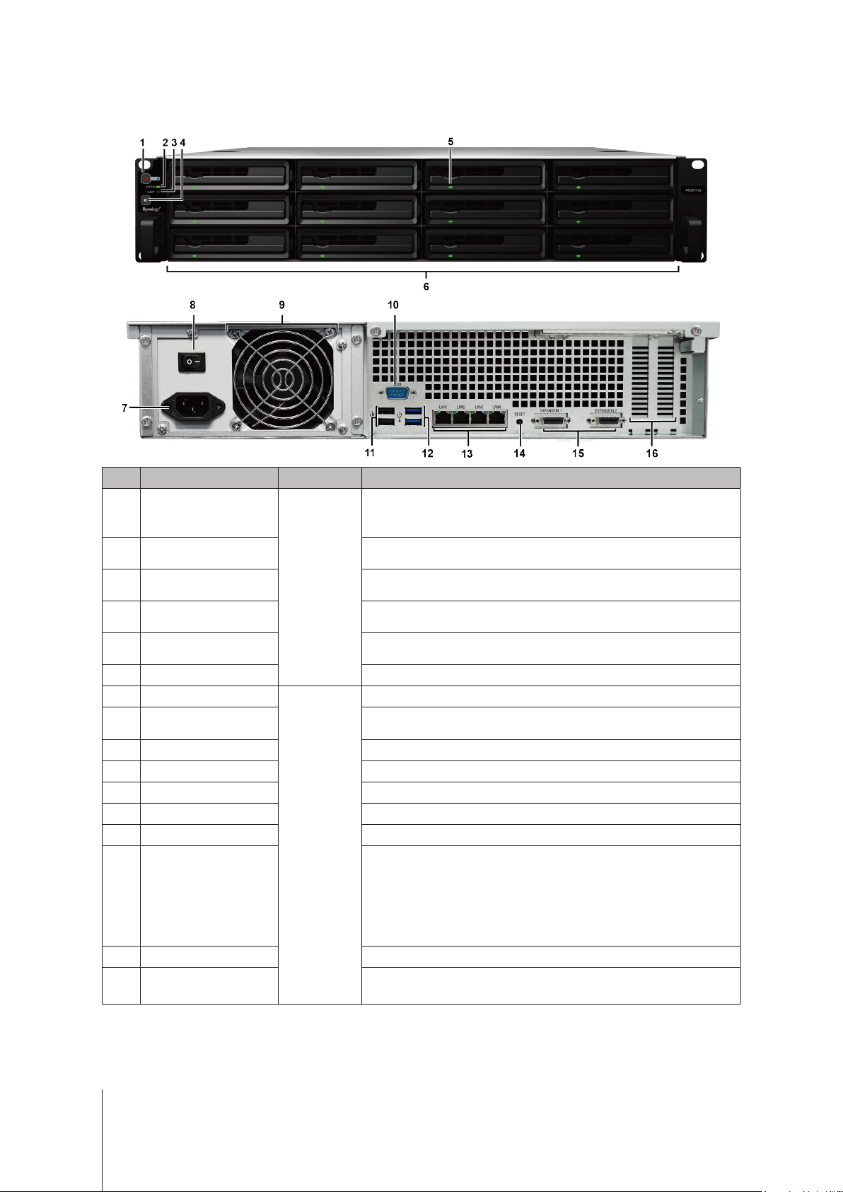
Synology RackStation at a Glance
No. Article Name Location Description
1. Press to power on the RackStation.
2. To power off the RackStation, press and hold until you hear a beep
sound and the Power LED starts blinking.
Displays the status of the system. For more information, see "Appendix B:
LED Indicator Table".
Displays warnings regarding fan or temperature. For more information,
see "Appendix B: LED Indicator Table".
Press to deactivate the beeping sound that is emitted when a malfunction
occurs.
Displays the status of drives. For more information, see "Appendix B:
LED Indicator Table".
Connect power cord here to supply power to your RackStation.
Press to turn on/off the power supply.
1. Press and hold until you hear a beep sound to restore the default IP
address, DNS server, and password for the
2. Press and hold until you hear a beep sound, then press and hold
again until you hear three beep sounds to return the RackStation
to "Not Installed" status so that DiskStation Manager (DSM) can be
reinstalled.
1
2
3
4
5
6
7
8
9
10
11
12
13
14
Power Button and
Indicator
Status Indicator
Alert Indicator
Front Panel
Beep Off Button
Drive Status Indicator
Drive Tray Install drives (hard disk drives or solid state drives) here.
Power Port
Power Supply On/Off
Switch
PSU Fan Disposes of excess heat and cools the PSU.
Console Port This port is used for manufacturing use only.
USB 2.0 Port Connect external drives, or other USB devices to the RackStation here.
USB 3.0 Port Connect external drives, or other USB devices to the RackStation here.
LAN Port Connect RJ-45 network cables here.
Back Panel
RESET Button
admin
account.
15
16
1
For more information about Synology Expansion Unit supported by your RackStation, please visit
2
White at x8 mode and black at x4 mode.
Expansion Port Connect Synology Expansion Units1 to your Synology RackStation.
PCI Express Expansion
Slot
Supports two PCIe x82 add-on network interface cards.
4 Chapter 1: Before You Start
www.synology.com
.
Page 5
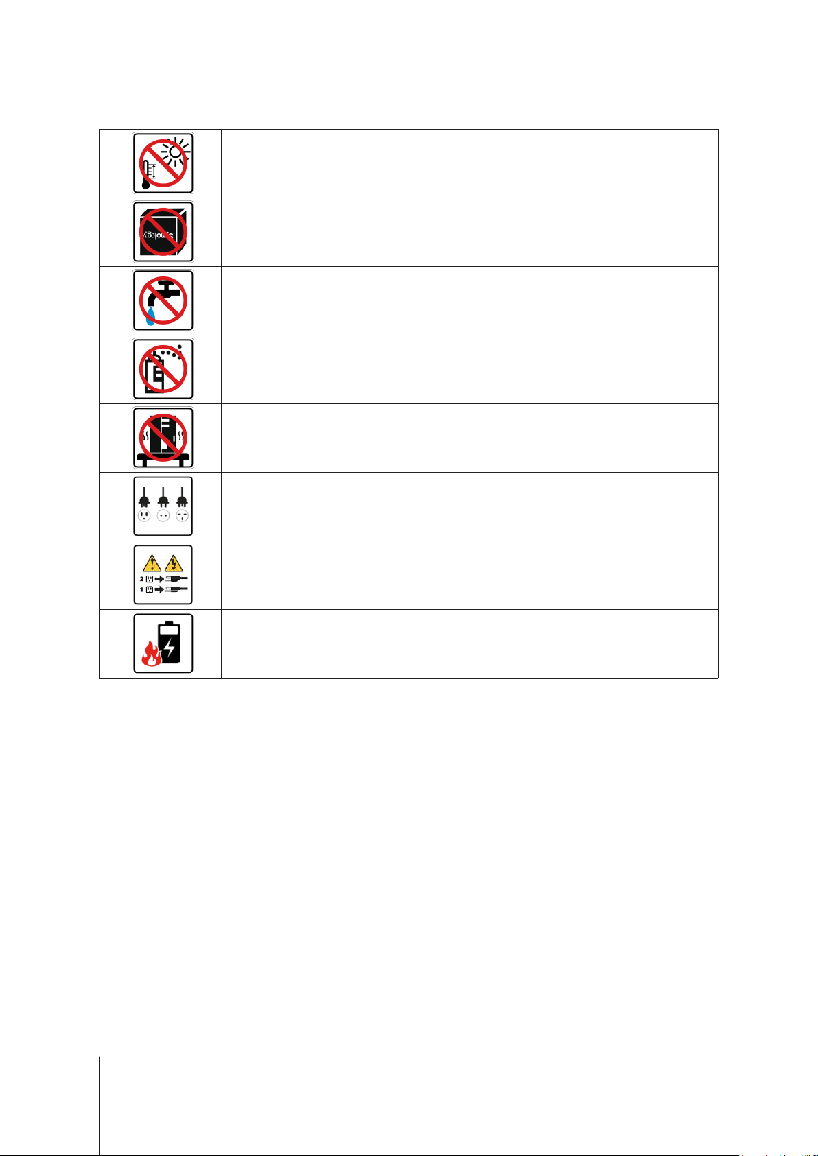
Safety Instructions
Keep away from direct sunlight and away from chemicals. Make sure the environment does not
experience abrupt changes in temperature or humidity.
Place the product right side up at all times.
Do not place near any liquids.
Before cleaning, unplug the power cord. Wipe with damp paper towels. Do not use chemical or
aerosol cleaners.
To prevent the unit from falling over, do not place on carts or any unstable surfaces.
The power cord must plug in to the correct supply voltage. Make sure that the supplied AC voltage is
correct and stable.
To remove all electrical current from the device, ensure that all power cords are disconnected from
the power source.
Risk of explosion if battery is replaced with an incorrect type. Dispose of used batteries appropriately.
5 Chapter 1: Before You Start
Page 6
Chapter
Hardware Setup
Tools and Parts for Drive Installation
• A screwdriver
• At least one 3.5” or 2.5” SATA drive (please visit
Warning:
back up any important data before installation.
If you install a drive that contains data, the system will format the drive and erase all existing data. Please
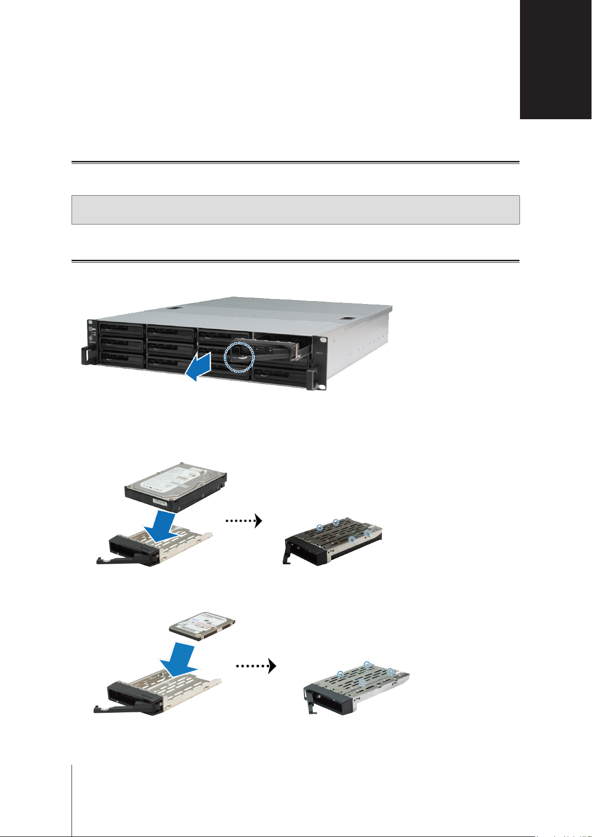
Install Drives
1
Find the small button located on the drive tray handle. Press the button down and pull the drive try handle out
as illustrated below.
www.synology.com
for compatible drive models.)
2
2
Load drives in the drive trays:
For 3.5” drives:
•
spots indicated below to secure the drive.
For 2.5” drives:
•
spots indicated below to secure the drive.
Place the drive in the drive tray. Turn the tray upside down and tighten screws into the four
Place the drive in the drive tray. Turn the tray upside down and tighten screws into the four
6
Page 7

3
Insert the loaded drive tray into the empty hard drive bay.
Important:
4
Push the handle inward to secure the drive tray.
5
Repeat the steps above to install all prepared drives.
6
Drives are numbered as shown below.
Note:
drive capacity usage.
Make sure the drive tray is completely inserted. Otherwise, the drive might not function properly.
If you want to create a RAID volume, we recommend all installed drives be the same size in order to optimize
7 Chapter 2: Hardware Setup
Page 8

Add a RAM Module on RackStation
Synology offers RAM modules which allow you to expand the memory capacity of your RackStation. To install,
check, or remove your RAM module, please follow the steps below.
To install a RAM module:
1
Shut down the RackStation and disconnect all connected cables to prevent any possible damage.
Important:
cord(s) from the RackStation to ensure complete discharge. Also, please remove any static electricity before
installation by touching water pipes, a metal conduit, or another person to get rid of excess charge and avoid
damaging the motherboard, peripherals, and other components.
2
Slide the latches shown below to release the fan cover.
3
Lift and remove the fan cover.
Before installing the RAM module, please wait for at least 30 seconds after detaching the power
8 Chapter 2: Hardware Setup
Page 9

4
To remove the screws securing the top cover, follow the steps below:
a
Remove the two screws illustrated below.
b
Remove the two screws located on the back. Then slide the top cover in the direction indicated below and
lift.
c
Remove the screws of the securing bracket and remove the securing bracket to reveal the RAM slots.
Important:
any other components when adding or removing memory.
Removing the cover will expose sensitive internal components to possible harm. Please avoid touching
9 Chapter 2: Hardware Setup
Page 10

5
To insert the new memory module, follow the steps below:
a
Release the ejectors on the memory slot by pushing them outwards.
b
Align the notch on the gold edge of the module with the notch in the memory slot.
c
Use two ngers to apply rm, even pressure and push the memory module downward.
d
When the memory is inserted correctly, the ejectors will snap into place.
6
Replace the top cover, slide it into place, and tighten all screws.
10 Chapter 2: Hardware Setup
Page 11

To make sure RackStation recognizes the new memory capacity:
1
Log in to DSM as
2
Total Physical Memory
Check
admin
or a user belonging to the
Control Panel
in
administrators
Info Center
>
group. .
.
If your RackStation does not recognize the memory or does not start up successfully, conrm that the memory
is installed correctly.
To remove the RAM Module:
1
Follow steps 1 to 4 of "Install a RAM Module" to remove the cover from the RackStation.
2
To remove the RAM module, follow the steps below:
a
Release the ejectors on the memory slot by pushing outwards simultaneously.
b
Hold the memory module by the edges and remove it from the slot.
3
Replace the top cover, slide it into place, and tighten the two back screws.
Add a Network Interface Card to RackStation
Your RackStation contains two PCI Express expansion slots which allow you to install two 10G/E or Gigabit
network interface cards for LAN port expansion.1 Before installation, make sure your network interface cards
come with "low-prole" brackets.
To replace a full-prole bracket with a low-prole bracket:
1
Remove the two screws holding the full-prole bracket to the interface card. Then remove the bracket.
1
For more information about supported 10G/E or Gigabit network interface cards, visit
11 Chapter 2: Hardware Setup
www.synology.com
.
Page 12

2
Tighten the screws to secure the low-prole bracket.
To install the network inter face card:
1
Follow steps 1 to 4 of "Install a RAM Module" to remove the cover from the RackStation.
2
To install the network interface card, follow the steps below:
a
Remove the screw on the port access cover. Then remove the access cover.
b
Align the card connector with the expansion slot and insert the card into the slot.
Important:
function properly. For greater perfomance, we highly recommend installing the network interface card into the PCI-E
3.0x8 (white) slot rst.
c
Tighten the screw to secure the network interface card.
Make sure the connector is fully inserted. Otherwise, the network interface card might not be able to
12 Chapter 2: Hardware Setup
Page 13

Replace System Fan
If a system fan malfunctions, please see the instructions below to open the RackStation and replace the
malfunctioning fan.
1
Slide the latches shown below to release the fan cover.
2
Lift to remove the fan cover.
3
Fans are numbered as shown below:
13 Chapter 2: Hardware Setup
Page 14

4
Find the malfunctioning fan and lift it upward to remove.
5
Apply rm pressure to the power plug and slide it off the power port as show below. Then remove the
malfunctioning fan from the fan casing.
6
Slide a new fan into the casing. Plug the power cord into the power port.
7
Slide the new cooling fan unit into the RackStation. Make sure the power port is aligned properly.
14 Chapter 2: Hardware Setup
Page 15

Start Up Your RackStation
1
Connect one end of the power cord to the power port located on the back of the RackStation.
2
Connect at least one LAN cable to one of the LAN ports and the other end to your switch, router, or hub.
3
Make sure the Power Supply On/Off Switch is turned on ("|").
15 Chapter 2: Hardware Setup
Page 16

4
Press the power button to turn on the RackStation.
Your RackStation is now online and detectable from a network computer.
16 Chapter 2: Hardware Setup
Page 17

Chapter
Install DSM on RackStation
After hardware setup is nished, please install DiskStation Manager (DSM) – Synology's browser-based operating
system – on your RackStation.
Install DSM with Web Assistant
Your RackStation comes with a built-in tool called
DSM from the Internet and install it on the RackStation. To use Web Assistant, please follow the steps below.
1
Power on the RackStation.
2
Open a web browser on a computer in the same network as the RackStation.
3
Enter either of the following into the address bar of your browser:
a nd.synology.com
b rackstation:5000
4
Web Assistant will be launched in your web browser. It will search and nd your RackStation within the local
network. The status of your RackStation should be
Web Assistant
Not Installed
that helps you download the latest version of
.
3
5
Connect
Click
Note:
1. The RackStation must be connected to the Internet to install DSM with Web Assistant.
2. Suggested browsers: Chrome, Firefox.
3. Both the RackStation and the computer must be in the same local network.
to start the setup process and follow the on-screen instructions.
Learn More
Congratulations! Your RackStation is now ready for action. For more information or online resources about your
RackStation, please visit
17
www.synology.com
.
Page 18

Appendix
Specications
Item RS3617xs
Internal Drive 3.5" / 2.5" SATA III / SATA II x 12
Maximum Raw Capacity
External Device Port
LAN Port 1GbE (RJ-45) x 4
PCIe Slot PCIe x8 Slot x 2 (White slot links at x8 mode, black slot links at x4 mode)
Size (H x W x D) (mm)
Weight (kg) 15.5
Supported Client
File System
A
• 96 TB (12 x 8 TB HDD)
• 288 TB with RX1217/RX1217RP (expansion unit) x 2
• USB 3.0 x 2
• USB 2.0 x 2
• Expansion port x2 (Inniband)
• 88 x 480 x 605 (Including rack mount kits)
• 88 x 445 x 570 (Not including rack mount kits)
• Windows 7 onwards
• Mac OS X 10.10 onwards
• Internal: Btrfs, ext4
• External: Btrfs, ext4, ext3, FAT, NTFS, HFS+
Supported RAID Type
Agency Certication • FCC Class A • CE Class A • BSMI Class A
HDD Hibernation Yes
Scheduled Power On/Off Yes
Wake on LAN Yes
Language Localization
Environment Requirement
Note:
Model specications are subject to change without notice. Please refer to
• Basic • JBOD • RAID 0 • RAID 1
• RAID 5 • RAID 6 • RAID 10
• Line voltage: 100V to 240V AC
• Frequency: 50/60Hz
• Operating Temperature: 40 to 95˚F (5 to 35˚C)
• Storage Temperature: -5 to 140˚F (-20 to 60˚C)
• Relative Humidity: 5% to 95% RH
www.synology.com
for the latest information.
18
Page 19

Appendix
LED Indicator Table
LED Indicator Color Status Description
Power
STATUS
ALERT
Drive Status Indicator
(on tray)
Rear LAN
(on left side of jack)
Blue
Green Static Volume normal
Orange Blinking
Orange Blinking Fan failure / Over temperature
Green
Red Static Drive error / Port disabled
Green
B
Static Powered on
Blinking Booting up / Shutting down
Off Powered off
Volume degraded / Volume crashed
Volume not created
DSM not installed
Off HDD hibernation
Off System normal
Static Drive ready and idle
Blinking Accessing drive
1
Off No internal drive
Static Network connected
Blinking Network active
Off No network
Green Static Gigabit connection
Rear LAN
(on right side of jack)
Note:
Model specications are subject to change without notice. Please refer to
1
Please try to restart your RackStation or re-insert the drive(s), and then run the HDD/SSD manufacturer's diagnostic tool to check the health status of the
drive(s). If you can log into DSM, please run the built-in S.M.A.R.T. test to scan the drive(s). If the problem remains unresolved, please contact Synology
Technical Support for help.
Orange Static 100 Mbps connection
Off 10 Mbps connection / No network
www.synology.com
for the latest information.
19
 Loading...