

Page 1
Synology RackStation RS2418+/RS2418RP+
Hardware Installation Guide
Page 2

Table of Contents
Chapter 1: Before You Start
Package Contents 3
Synology RackStation at a Glance 4
Safety Instructions 6
Chapter 2: Hardware Setup
Tools and Parts for Drive Installation 7
Install Drives 7
Add a RAM Module on RackStation 9
Attach Network Interface Cards to the RackStation 12
Replace System Fan 13
Replace Redundant PSU1 on RackStation 14
Start Up Your RackStation 15
Chapter 3: Install DSM on RackStation
Install DSM with Web Assistant 16
Learn More 16
Appedix A: Specications
Appedix B: LED Indicator Table
Synology_HIG_RS2418(RP)+_20170921
2
Page 3
Chapter
Before You Start
Thank you for purchasing this Synology product! Before setting up your new RackStation, please check the
package contents to verify that you have received the items below. Also, make sure to read the safety instructions
carefully to avoid harming yourself or damaging your RackStation.
Note:
All images below are for illustrative purposes only, and may dier from the actual product.
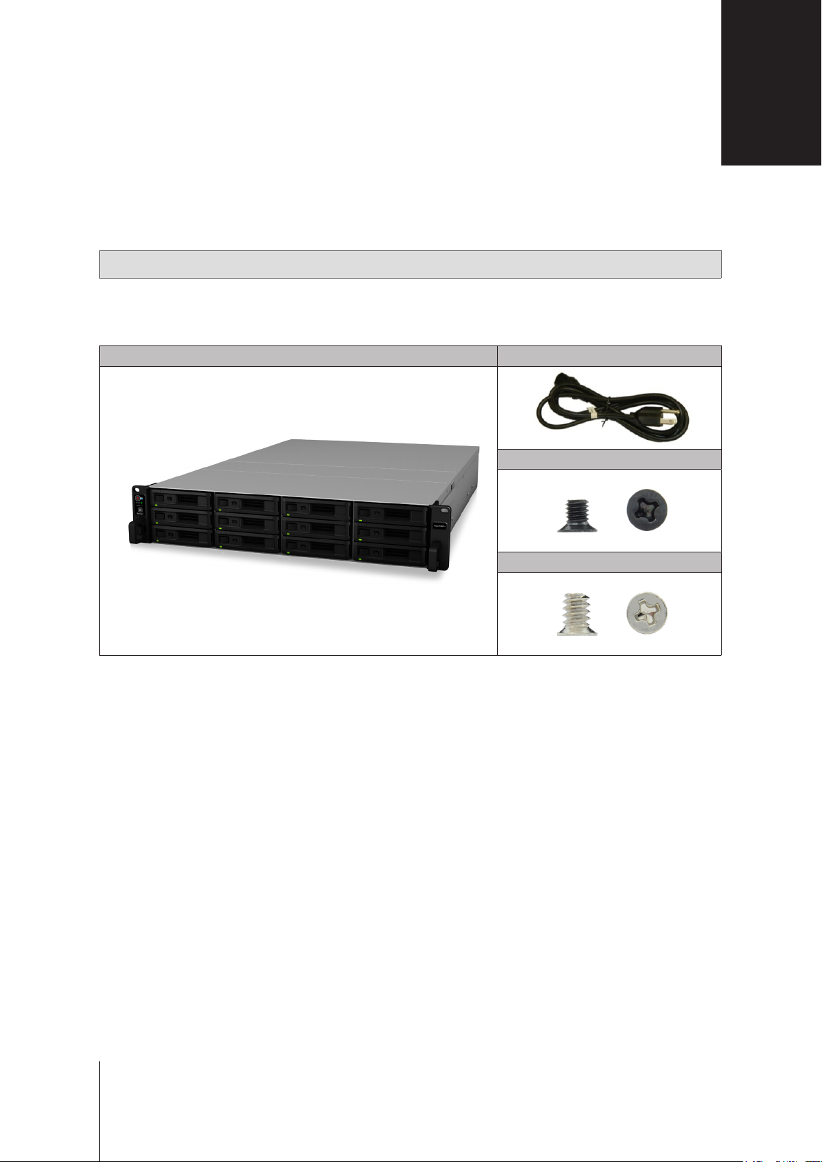
Package Contents
Main unit x 1 AC power cord
Screws for 2.5” drives x 52
1
1
Screws for 3.5” drives x 52
1
AC power cord: RS2418+ x1; RS2418RP+ x2
3
3
Page 4
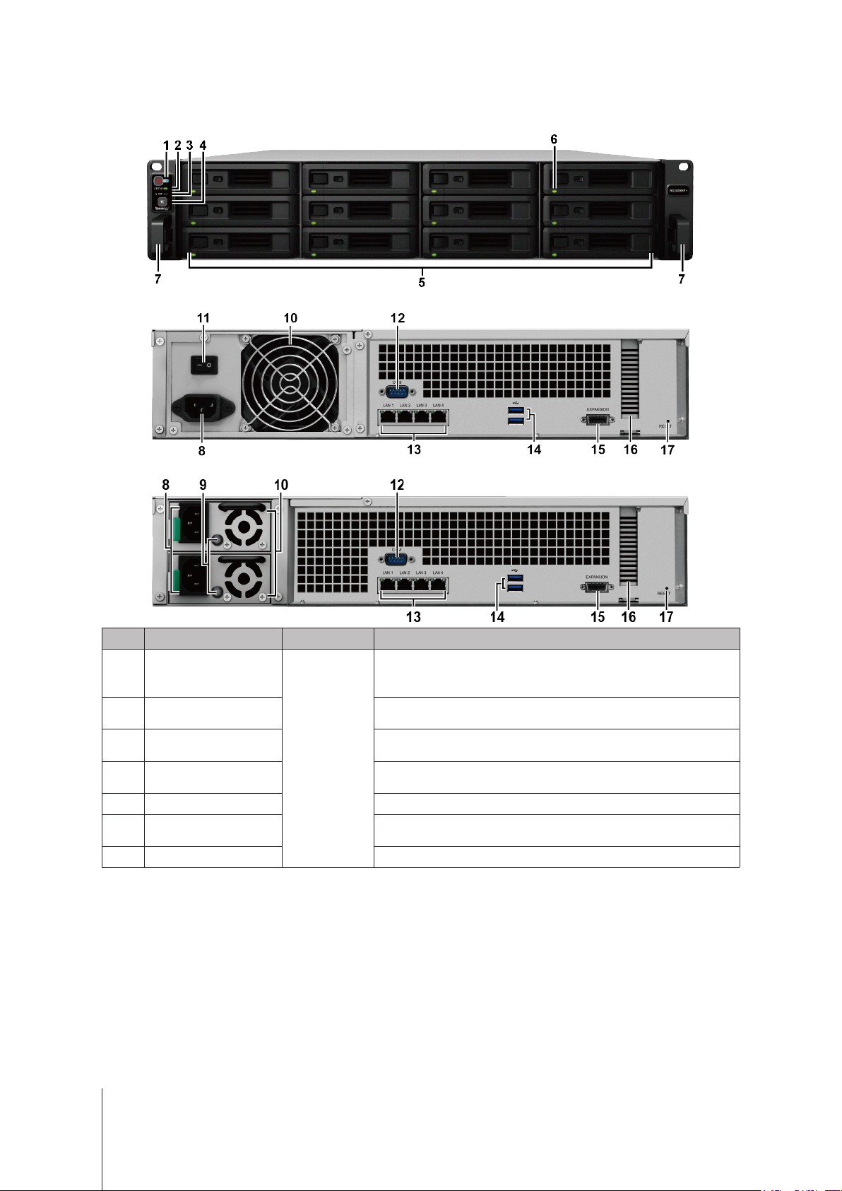
Synology RackStation at a Glance
RS2418+
RS2418RP+
No. Article Name Location Description
1
2
3
4
5
6
7
Power Button and
Status Indicator
Beep O Button
Drive Status Indicator
Rail Kit Release Tab Push in and hold to release the RackStation from the rail kit lock.
Indicator
Alert Indicator
Front Panel
Drive Tray Install drives (hard disk drives or solid state drives) here.
1. Press to power on the RackStation.
2. To power o the RackStation, press and hold until you hear a beep
sound and the Power LED starts blinking.
Displays the status of the system. For more information, see "Appendix
B: LED Indicator Table".
Displays warnings regarding fan or temperature. For more information,
see "Appendix B: LED Indicator Table".
Press to deactivate the beeping sound that is emitted when a
malfunction occurs.
Displays the status of drives. For more information, see "Appendix B:
LED Indicator Table".
1
1
For more information about the rail kit installation, please refer to the Quick Installation Guide that comes with the rail kit.
4 Chapter 1: Before You Start
Page 5
No. Article Name Location Description
8
Power Port
Connect power cords here.
1. Displays the status of the power supply unit (PSU). For more
PSU Indicator and Beep
9
O Button
information, see "Appendix B: LED Indicator Table".
2. Press to deactivate the beeping sound that is emitted when a
malfunction occurs.
10
11
12
13
14
15
16
PSU Fan Disposes of excess heat and cools the PSU.
Power Supply On/O
Switch
Press to turn on/o the power supply.
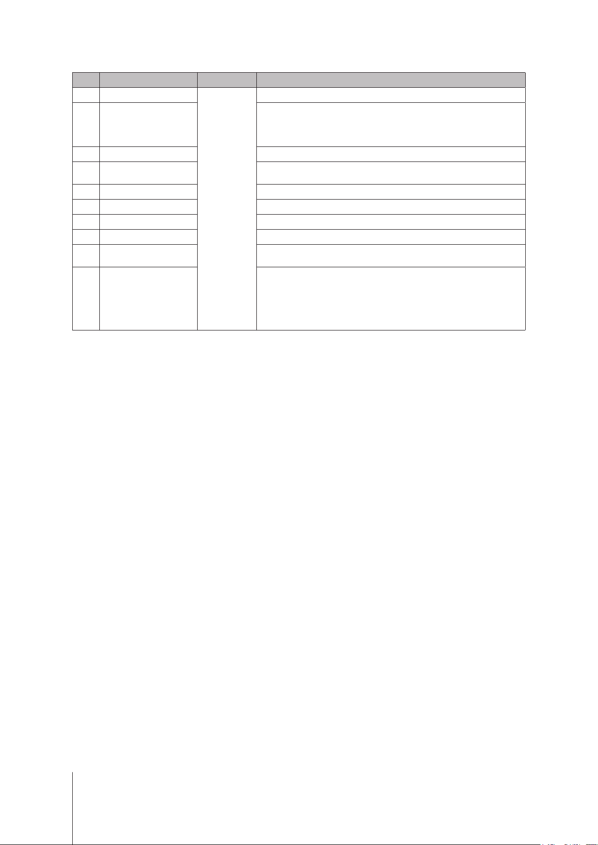
Console Port This port is used for manufacturing use only.
LAN Port Connect RJ-45 network cables here.
Back Panel
USB 3.0 Port Connect external drives, or other USB devices to the RackStation here.
Expansion Port Connect to Synology Expansion Unit2 here.
PCI Express
Expansion Slot
Supports one PCIe x8 slot (x4 link) add-on card.
1. Press and hold until you hear a beep sound to restore the default IP
address, DNS server, and password for the
17
RESET Button
2. Press and hold until you hear a beep sound, then press and hold
again until you hear three beep sounds to return the RackStation
to “Not Installed” status so that DiskStation Manager (DSM) can be
reinstalled.
admin
account.
2
For more information about Synology Expansion Unit supported by your RackStation, please visit
5 Chapter 1: Before You Start
www.synology.com
.
Page 6
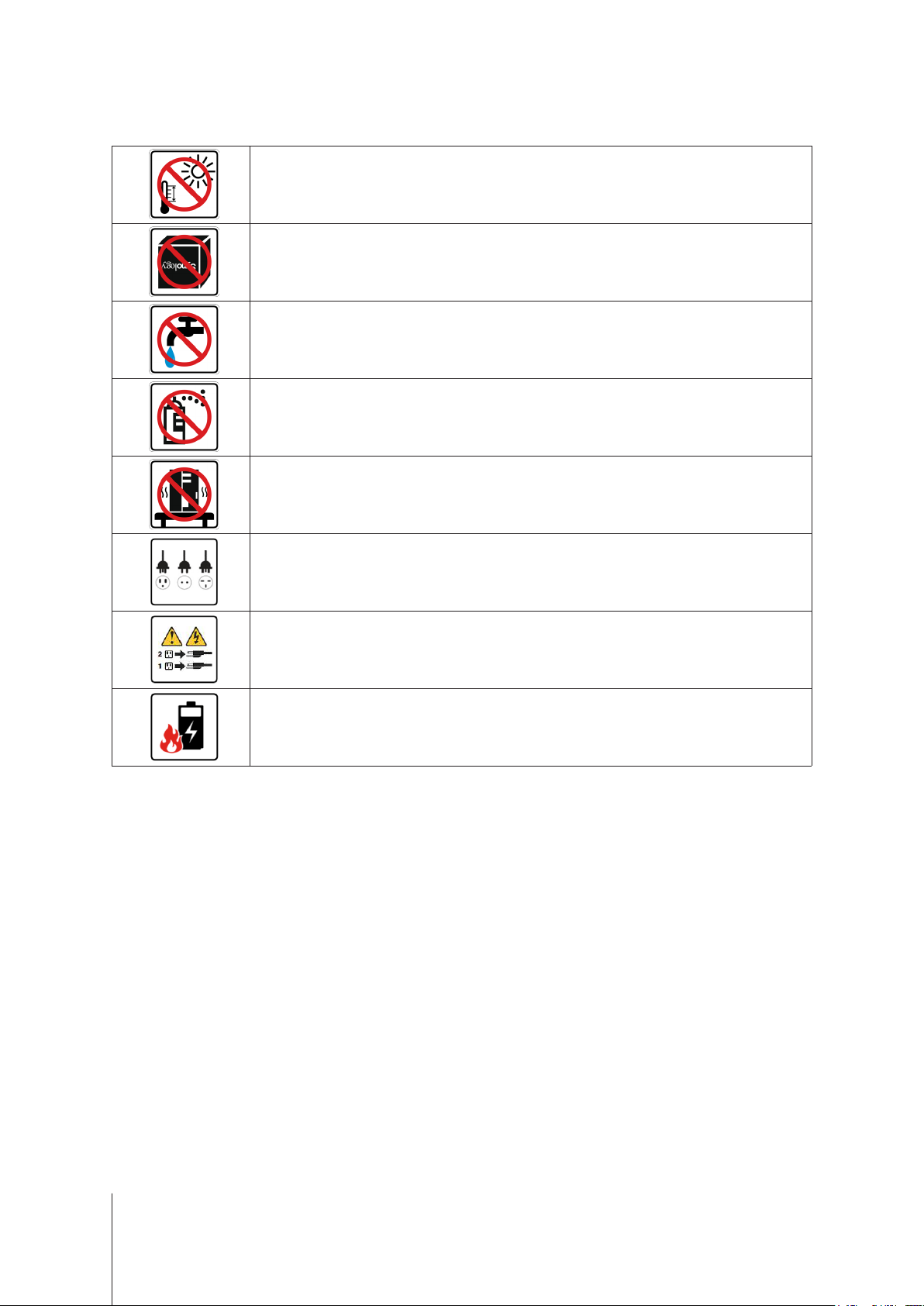
Safety Instructions
Keep away from direct sunlight and away from chemicals. Make sure the environment does not
experience abrupt changes in temperature or humidity.
Place the product right side up at all times.
Do not place near any liquids.
Before cleaning, unplug the power cord. Wipe with damp paper towels. Do not use chemical or
aerosol cleaners.
To prevent the unit from falling over, do not place on carts or any unstable surfaces.
The power cord must plug in to the correct supply voltage. Make sure that the supplied AC voltage is
correct and stable.
To remove all electrical current from the device, ensure that all power cords are disconnected from
the power source.
Risk of explosion if battery is replaced with an incorrect type. Dispose of used batteries appropriately.
6 Chapter 1: Before You Start
Page 7
Chapter
Hardware Setup
Tools and Parts for Drive Installation
• A screwdriver
• At least one 3.5” or 2.5” SATA drive (please visit
Warning:
back up any important data before installation.
If you install a drive that contains data, the system will format the drive and erase all existing data. Please
Install Drives
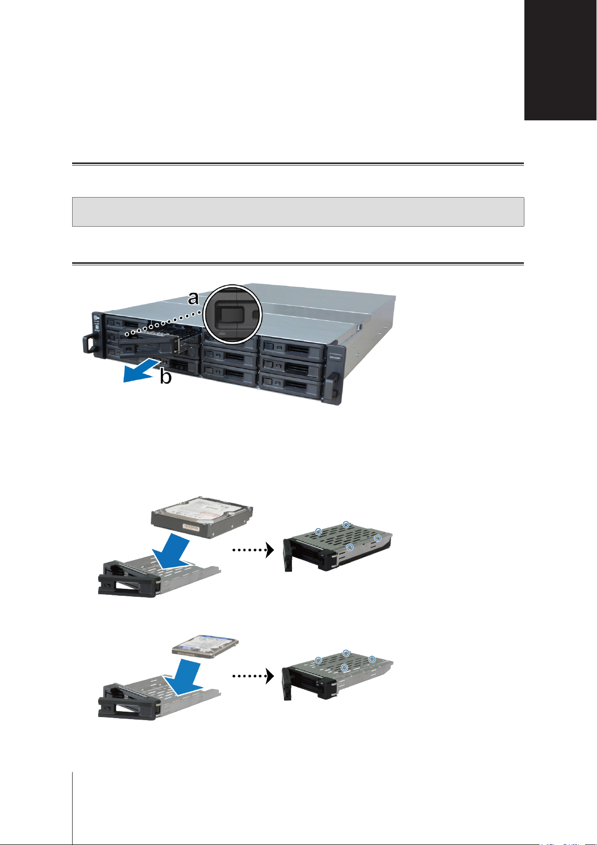
1
Open the drive tray.
www.synology.com
2
for compatible drive models.)
a
Find the small button located on the left side of the drive tray handle. Press the button down, and the drive
tray handle will pop out.
b
Pull the drive tray handle out as illustrated above.
2
Install drives:
For 3.5” drives:
•
spots indicated below to secure the drive.
For 2.5” drives:
•
spots indicated below to secure the drive.
Place the drive in the drive tray. Turn the tray upside down and tighten screws into the four
Place the drive in the drive tray. Turn the tray upside down and tighten screws into the four
7
Page 8
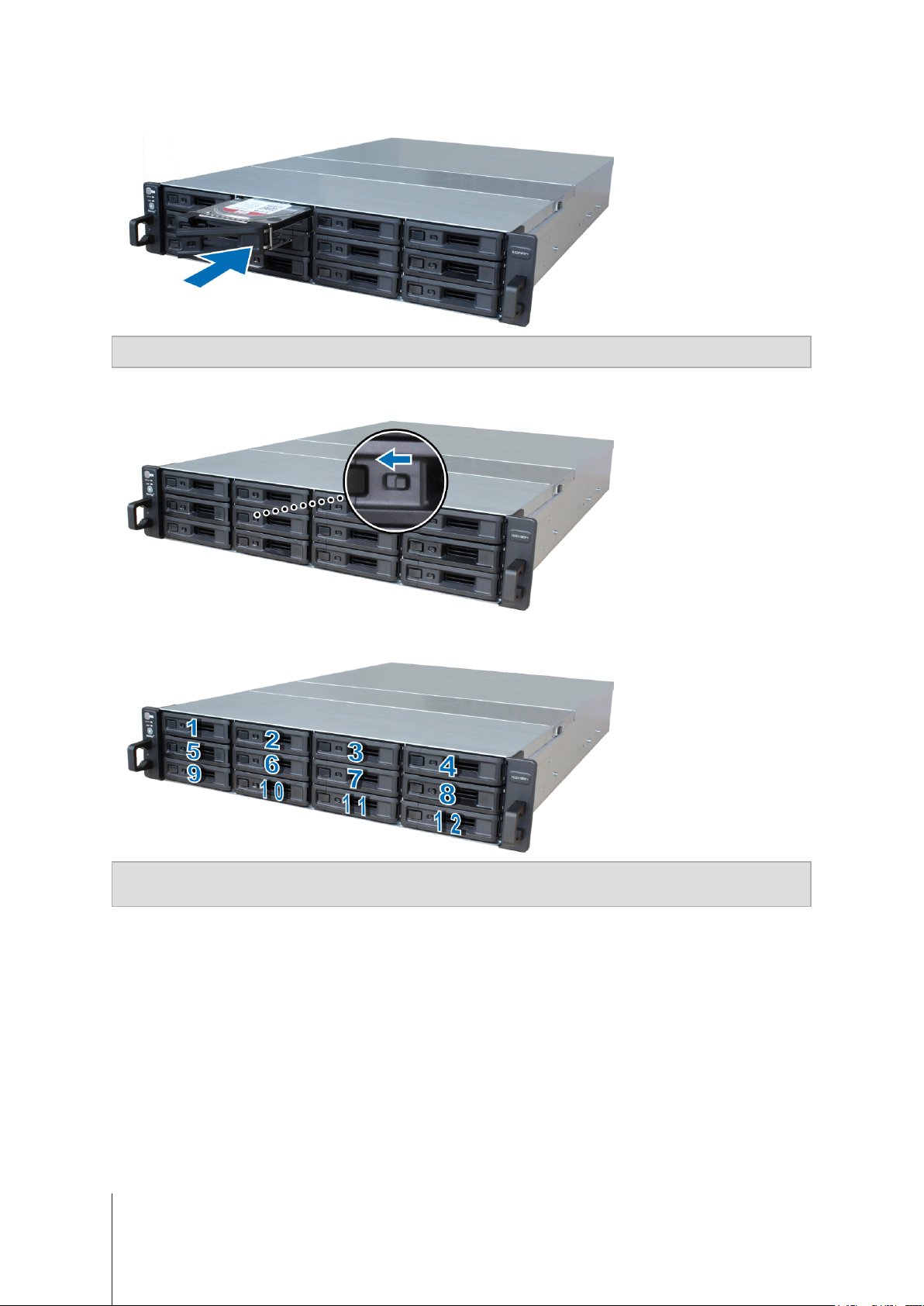
3
Insert the loaded drive tray into the empty drive bay.
Note:
Make sure the tray is pushed in all the way. Otherwise, the drive might not be able to function properly.
4
Push the handle inward to secure the drive tray.
5
Push the switch on the drive tray handle to the left to lock the drive tray.
6
Repeat the steps above to assemble the other drives you have prepared.
7
Drives are numbered as shown below.
Note:
If you want to create a RAID volume, we recommend all installed drives be the same size in order to optimize
drive capacity usage.
8 Chapter 2: Hardware Setup
Page 9

Add a RAM Module on RackStation
The optional Synology RAM module is designed for RackStation memory expansion. Follow the steps below to
install, check, or remove a RAM module on your RackStation.
To install the RAM module:
1
Shut down your RackStation. Disconnect all cables connected to your RackStation to prevent any possible
damage.
2
Remove the rear top cover:
a
Remove the screw on the back of RackStation.
b
Pull the rear top cover, and put it aside.
Note:
When you remove the rear top cover, you expose sensitive internal components. Avoid touching anything other
than the memory assembly when you remove or add memory.
9 Chapter 2: Hardware Setup
Page 10

3
Insert the new memory module in the slot:
a
Push the retaining clips on the slot out to the sides.
b
Align the notch on the gold edge of the module with the notch in the memory slot.
c
Push down on the memory module with rm and even pressure. The retaining clips will snap into position as
the module is correctly inserted.
Important:
• You must utilize the same type of memory on all slots. The default memory is non-ECC, UDIMM DDR4.
Note:
4
Put back the rear top cover you lifted in step 2.
a
• For normal operations, you must insert your memory modules into the
If you expand utilizing ECC, UDIMM DDR4 memory, you must remove the original.
• Hold the memory module by its edges, and do not touch the gold connectors.
• When memory capacity is changed, the device will perform a memory check upon the next start up. This will
prolong the start up time by up to ten minutes. This behavior is normal and will only occur once.
Align the round dots at the side of rear top cover with the slots on the chassis’ edge, and push the rear top
white
slots rst.
cover back in position.
b
Put back and fasten the screw you removed in step 2-a.
To make sure RackStation recognizes the new memory capacity:
1
Log in to DSM as
2
Total Physical Memory
Check
admin
or a user belonging to the
Control Panel
in
administrators
Info Center
>
group.
.
If your RackStation does not recognize the memory or does not start up successfully, conrm that the memory is
installed correctly.
10 Chapter 2: Hardware Setup
Page 11

To remove the RAM Module:
1
Follow step 1 and 2 of the “To install the RAM module” section to shut down your RackStation, disconnect the
cables, and then remove the rear top cover.
2
Push the levers on the sides of the memory module in an outward direction to release the module from the
memory card slot.
3
Hold the memory module by its notches and remove it from the slot.
4
Follow step 4 of the “To install the RAM module” section to put back the rear top cover.
11 Chapter 2: Hardware Setup
Page 12

Attach Network Interface Cards to the RackStation
Your RackStation supports one PCIe x8 add-on network interface card.1 You need to replace the long bracket
(suited for PC) in your network interface card with the short bracket before installing the card on your RackStation.
To install the network inter face card:
1
Shut down your RackStation. Disconnect all cables connected to your RackStation to prevent any possible
damages.
2
Open the RackStation by following step 2 of
3
Install the network interface card.
a
Remove the screw that secures the expansion slot’s cover. Then, lift the expansion slot’s cover.
b
Align the card’s connector with the expansion slot, and insert the card into the slot.
c
Put back and fasten the screw that you removed in step 3-a so as to secure the newly inserted card.
Note:
Make sure the connector is fully inserted. Otherwise, the network interface card might not be able to function
properly.
Add a RAM Module on RackStation
.
4
Put back the rear top cover by following step 4 of
1
For more information about supported 10GbE or Gigabit network interface cards, please visit
Add a RAM Module on RackStation
12 Chapter 2: Hardware Setup
www.synology.com
.
.
Page 13

Replace System Fan
If a system fan malfunctions, please see the instructions below to open the RackStation and replace the
malfunctioning fan.
1
Press the small buttons located on the sides of the RackStation.
2
Lift to remove the fan cover.
3
Fans are numbered as indicated below:
4
Find the malfunctioning fan. Lift the fan upward to remove it.
13 Chapter 2: Hardware Setup
Page 14

5
Prepare a new fan, and slide it into the RackStation. Make sure the fan is aligned properly as illustrated below.
6
Put back the fan cover you removed in step 2.
Replace Redundant PSU on RackStation
If a PSU1 or its fan malfunctions, please see the instructions below to replace the malfunctioning PSU.
1
Unplug the power cord from the PSU to be replaced.
Note:
By pressing the
2
Push the lever of the PSU at the back panel in the indicated direction.
3
Pull out the PSU from the RackStation.
4
Prepare a new PSU, and push it back to the slot until you hear a click.
Beep O
button, you can silence the long beeping sound when you hear it.
1
Only for RS2418RP+.
14 Chapter 2: Hardware Setup
Page 15

Start Up Your RackStation
1
Connect one end of each power cord to the power ports located on the back of the RackStation and the other
end to a power outlet.
2
Connect at least one LAN cable to one of the LAN ports and the other end to your switch, router, or hub.
3
Make sure the Power Supply On/O Switch2 is turned on (“─”).
4
Press the power button to turn on the RackStation.
Congratulations! Your RackStation is now online and detectable from a network computer.
2
Only for RS2418+.
15 Chapter 2: Hardware Setup
Page 16

Chapter
Install DSM on RackStation
After hardware setup is nished, please install DiskStation Manager (DSM) – Synology’s browser-based
operating system – on your RackStation.
Install DSM with Web Assistant
Your RackStation comes with a built-in tool called
DSM from the Internet and install it on your RackStation. To use Web Assistant, please follow the steps below.
1
Power on the RackStation.
2
Open a web browser on a computer connected to the same network as the RackStation.
3
Enter either of the following into the address bar of your browser:
a nd.synology.com
b rackstation:5000
4
Web Assistant will be launched in your web browser. It will search for and nd the RackStation within the local
network. The status of the RackStation should be
Web Assistant
Not Installed
that helps you download the latest version of
.
3
5
6
Connect
Click
Note:
1. The RackStation must be connected to the Internet to install DSM with Web Assistant.
2. Suggested browsers: Chrome, Firefox.
3. Both the RackStation and the computer must be in the same local network.
If you accidentally leave the installation process before it is nished, login to the DSM as
administrative account name) with the password left blank.
to start the setup process and follow the onscreen instructions.
admin
(default
Learn More
Congratulations! Your RackStation is now ready for action. For more information or online resources about your
RackStation, please visit
16
www.synology.com
.
Page 17

Appendix
Specications
Item RS2418+ / RS2418RP+
Internal Drive 3.5” / 2.5” SATA x 12
Maximum Raw Capacity
External Device Port
LAN Port 1GbE (RJ-45) x 4
PCIe Slot PCIe Gen3 x8 slot (x4 link) for add-on card (optional) x 1
Size (H x W x D) (mm)
Weight (kg)
Supported Client
A
• 144 TB (12 x 12 TB HDD)
• 288 TB with RX1217 / RX1217RP (expansion unit) x 1
• USB 3.0 x 2
• Inniband x 1
• RS2418+: 88 x 430.5 x 664 (Not including rack mount kits) /
88 x 482 x 696 (Including rack mount kits)
• RS2418RP+: 88 x 430.5 x 692 (Not including rack mount kits) /
88 x 482 x 724 (Including rack mount kits)
• RS2418+: 13.22
• RS2418RP+: 13.85
• Windows 7 and 10
• Mac OS X 10.11 onward
File System
Supported RAID Type
Agency Certication • FCC Class A • CE Class A • BSMI Class A
HDD Hibernation Yes
Scheduled Power On/O Yes
Wake on LAN Yes
Language Localization
Environment Requirement
Note:
Model specications are subject to change without notice. Please refer to
• External: Btrfs, ext4, ext3, FAT, NTFS, HFS+, exFAT
• Synology Hybrid RAID (Up to 2-Disk Fault Tolerance)
• Operating Temperature: 40 to 95°F (5 to 35°C)
• Storage Temperature: -5 to 140°F (-20 to 60°C)
• Internal: Btrfs, ext4
• Basic • JBOD • RAID 0 • RAID 1
• RAID 5 • RAID 6 • RAID 10
• Line voltage: 100V to 240V AC
• Frequency: 50/60Hz
• Relative Humidity: 5% to 95% RH
www.synology.com
for the latest information.
1
1
Support for exFAT can be enabled by purchasing and downloading exFAT Access in Package Center.
17
Page 18

Appendix
LED Indicator Table
LED Indicator Color Status Description
Power
STATUS
ALERT
Drive Status Indicator
(on tray)
PSU Indicator
Rear LAN
(on left side of jack)
2
Blue
Green Static Volume normal
Orange Blinking
Orange Blinking Fan failure / Over temperature
Green
Red Static Drive error
Green Static Power supply unit normal
Green
B
Static Powered on
Blinking Booting up / Shutting down
O Powered o
Volume degraded / Volume crashed
Volume not created
DSM not installed
O HDD hibernation
O System normal
Static Drive ready and idle
Blinking Accessing drive
1
O No internal drive
O Power supply unit o
Static Network connected
Blinking Network active
O No network
Green Static 1 Gbps connection
Rear LAN
(on right side of jack)
Note:
Model specications are subject to change without notice. Please refer to
1
Please try to restart your RackStation or re-insert the drive(s), and then run the HDD/SSD manufacturer's diagnostic tool to check the health status of the
drive(s). If you can log into DSM, please run the built-in S.M.A.R.T. test to scan the drive(s). If the problem remains unresolved, please contact Synology
Technical Support for help.
2
Only for RS2418RP+.
Orange Static 100 Mbps connection
O 10 Mbps connection / No network
www.synology.com
for the latest information.
18
Page 19

SYNOLOGY, INC.
END USER LICENSE AGREEMENT
IMPORTANT–READ CAREFULLY: THIS END USER LICENSE AGREEMENT ("EULA") IS A LEGAL AGREEMENT
BETWEEN YOU (EITHER AN INDIVIDUAL OR A LEGAL ENTITY) AND SYNOLOGY, INC. ("SYNOLOGY") FOR THE
SYNOLOGY SOFTWARE INSTALLED ONTO THE SYNOLOGY PRODUCT PUCHASED BY YOU (THE "PRODUCT"),
OR LEGALLY DOWNLOADED FROM WWW.SYNOLOGY.COM, OR ANY OTHER CHANNEL PROVIDED BY
SYNOLOGY ( "SOFTWARE").
YOU AGREE TO BE BOUND BY THE TERMS OF THIS EULA BY USING THE PRODUCTS CONTAINING THE
SOFTWARE, INSTALLING THE SOFTWARE ONTO THE PRODUCTS OR DEVICE CONNECTED TO THE PRODUCTS.
IF YOU DO NOT AGREE TO THE TERMS OF THIS EULA, DO NOT USETHE PRODUCTS CONTAINING THE
SOFTWAREOR DOWNLOAD THE SOFTWARE FROM WWW.SYNOLOGY.COM, OR ANY OTHER CHANNEL
PROVIDED BY SYNOLOGY.INSTEAD, YOU MAY RETURN THE PRODUCT TO THE RESELLER WHERE YOU
PURCHASED IT FOR A REFUND IN ACCORDANCE WITH THE RESELLER'S APPLICABLE RETURN POLICY.
Section 1. Limited Software License. Subject to the terms and conditions of this EULA, Synology grants you a limited, nonexclusive, non-transferable, personal license to install, run and use one copy of the Software loaded on the Product or on
your device connected to the Product solely relating to your authorized use of the Product.
Section 2. Documentation. You may make and use a reasonable number of copies of any documentation provided with the
Software; provided that such copies will only be used for internal business purposes and are not to be republished or
redistributed (either in hard copy or electronic form) to any third party.
Section 3. Backup. You may make a reasonable number of copies of the Software for backup and archival purposes only.
Section 4. Updates. Any software provided to you by Synology or made available on the Synology website at
www.synology.com ("Website") or any other channel provided by Synology that updates or supplements the original
Software is governed by this EULA unless separate license terms are provided with such updates or supplements, in which
case, such separate terms will govern.
Section 5. License Limitations. The license set forth in Sections 1, 2 and 3 applies only to the extent that you have ordered
and paid for the Product and states the entirety of your rights with respect to the Software. Synology reserves all rights not
expressly granted to you in this EULA. Without limiting the foregoing, you shall not authorize or permit any third party to: (a)
use the Software for any purpose other than that in connection with the Product; (b) license, distribute, lease, rent, lend,
transfer, assign or otherwise dispose of the Software; (c) reverse engineer, decompile, disassemble or attempt to discover
the source code of or any trade secrets related to the Software, except and only to the extent that such conduct is
expressly permitted by applicable law notwithstanding this limitation; (d) adapt, modify, alter, translate or create any
derivative works of the Software; (e) remove, alter or obscure any copyright notice or other proprietary rights notice on the
Software or Product; or (f) circumvent or attempt to circumvent any methods employed by Synology to control access to the
components, features or functions of the Product or Software. Subject to the limitations specified in this Section 5, you are
not prohibited from providing any services hosted by Synology NAS server to any third party for commercial purpose.
Section 6. Open Source. The Software may contain components licensed to Synology under the GNU General Public
License ("GPL Components"), currently available at http://www.gnu.org/licenses/gpl.html. The terms of the GPL will control
solely with respect to the GPL Components to the extent that this EULA conflicts with the requirements of the GPL with
respect to your use of the GPL Components, and, in such event, you agree to be bound by the GPL with respect to your
use of such components.
Section 7. Audit. Synology will have the right to audit your compliance with the terms of this EULA. You agree to grant
Synology a right to access to your facilities, equipment, books, records and documents and to otherwise reasonably
cooperate with Synology in order to facilitate any such audit by Synology or its agent authorized by Synology.
Section 8. Ownership. The Software is a valuable property of Synology and its licensors, protected by copyright and other
intellectual property laws and treaties. Synology or its licensors own all rights, titles and interests in and to the Software,
including but not limited to copyright and any other intellectual property rights.
Section 9. Limited Warranty. Synology provides a limited warrant that the Software will substantially conform to Synology's
published specifications for the Software, if any, or otherwise set forth on the Website, for a period required by your local
law. Synology will use commercially reasonable efforts to, in Synology's sole discretion, either correct any such
nonconformity in the Software or replace any Software that fails to comply with the foregoing warranty, provided that you
give Synology written notice of such noncompliance within the warranty period. The foregoing warranty does not apply to
any noncompliance resulting from any: (w) use, reproduction, distribution or disclosure not in accordance with this EULA;
(x) any customization, modification or other alteration of the Software by anyone other than Synology; (y) combination of
the Software with any product, services or other items provided by anyone other than Synology; or (z) your failure to
comply with this EULA.
Section 10. Support. During the period specified in the Section 9, Synology will make available to you the support services.
Following the expiration of the applicable period, support for Software may be available from Synology upon written
Page 20

request.
Section 11. Disclaimer of Warranties. EXCEPT AS EXPRESSLY SET FORTH ABOVE, THE SOFTWARE IS PROVIDED
"AS IS" AND WITH ALL FAULTS. SYNOLOGY AND ITS SUPPLIERS HEREBY DISCLAIM ALL OTHER WARRANTIES,
EXPRESS, IMPLIED OR STATUTORY, ARISING BY LAW OR OTHERWISE, INCLUDING BUT NOT LIMITED TO ANY
IMPLIED WARRANTIES OF MERCHANTABILITY, FITNESS FOR A PARTICULAR PURPOSE OR USE, TITLE AND
NONINFRINGEMENT, WITH REGARD TO THE SOFTWARE. WITHOUT LIMITING THE FOREGOING, SYNOLOGY
DOES NOT WARRANT THAT THE SOFTWARE WILL BE FREE OF BUGS, ERRORS, VIRUSES OR OTHER DEFECTS.
Section 12. Disclaimer of Certain Damages. IN NO EVENT WILL SYNOLOGY OR ITS LICENSORS BE LIABLE FOR ANY
INCIDENTAL, INDIRECT, SPECIAL, PUNITIVE, CONSEQUENTIAL OR SIMILAR DAMAGES OR LIABILITIES
WHATSOEVER (INCLUDING, BUT NOT LIMITED TO LOSS OF DATA, INFORMATION, REVENUE, PROFIT OR
BUSINESS) ARISING OUT OF OR RELATING TO THE USE OF OR INABILITY TO USE THE SOFTWARE OR
OTHERWISE UNDER OR IN CONNECTION WITH THIS EULA OR THE SOFTWARE, WHETHER BASED ON
CONTRACT, TORT (INCLUDING NEGLIGENCE), STRICT LIABILITY OR OTHER THEORY EVEN IF SYNOLOGY HAS
BEEN ADVISED OF THE POSSIBILITY OF SUCH DAMAGES.
Section 13. Limitation of Liability. SYNOLOGY'S AND ITS SUPPLIERS' LIABILITY ARISING OUT OF OR RELATING TO
THE USE OF OR INABILITY TO USE THE SOFTWARE OR OTHERWISE UNDER OR IN CONNECTION WITH THIS
EULA OR THE SOFTWARE IS LIMITED TO THE AMOUNT ACTUALLY PAID BY YOU FOR THE PRODUCT
REGARDLESS OF THE AMOUNT OF DAMAGES YOU MAY INCUR AND WHETHER BASED ON CONTRACT, TORT
(INCLUDING NEGLIGENCE), STRICT LIABILITY OR OTHER THEORY. The foregoing disclaimer of warranties,
disclaimer of certain damages and limitation of liability will apply to the maximum extent permitted by applicable law. The
laws of some states/jurisdictions do not allow the exclusion of implied warranties or the exclusion or limitation of certain
damages. To the extent that those laws apply to this EULA, the exclusions and limitations set forth above may not apply to
you.
Section 14. Export Restrictions. You acknowledge that the Software is subject to U.S. export restrictions. You agree to
comply with all applicable laws and regulations that apply to the Software, including without limitation the U.S. Export
Administration Regulations.
Section 15. Termination. Without prejudice to any other rights, Synology may terminate this EULA if you do not abide by
the terms and conditions contained herein. In such event, you must cease use of the Software and destroy all copies of the
Software and all of its component parts.
Section 16. Assignment. You may not transfer or assign your rights under this EULA to any third party, except for that preinstalled in the Products. Any such transfer or assignment in violation of the foregoing restriction will be void.
Section 17. Applicable Law. Unless expressly prohibited by local law, this EULA is governed by and construed in
accordance with the laws of the country, in accordance with which Synology Inc. was organized without regard to any
conflict of law principles to the contrary.
Section 18. Dispute Resolution. Any dispute, controversy or claim arising out of or relating to this EULA will be resolved
exclusively and finally by arbitration conducted by three neutral arbitrators in accordance with the procedures of the
Arbitration Law and related enforcement rules of the country in which Synology Inc. was organized. In such cases, the
arbitration will be limited solely to the dispute between you and Synology. The arbitration, or any portion of it, will not be
consolidated with any other arbitration and will not be conducted on a class-wide or class action basis. The arbitration shall
take place in Taipei and the arbitration proceedings shall be conducted in English or, if both parties so agree, in Mandarin
Chinese. The arbitration award shall be final and binding on the parties and may be enforced in any court having
jurisdiction. You understand that, in the absence of this provision, you would have had a right to litigate any such dispute,
controversy or claim in a court, including the right to litigate claims on a class-wide or class-action basis, and you expressly
and knowingly waives those rights and agrees to resolve any disputes through binding arbitration in accordance with the
provisions of this Section 18. Nothing in this Section shall be deemed to prohibit or restrict Synology from seeking injunctive
relief or seeking such other rights and remedies as it may have at law or equity for any actual or threatened breach of any
provision of this EULA relating to Synology's intellectual property rights.
Section 19. Attorneys' Fees. In any arbitration, mediation, or other legal action or proceeding to enforce rights or remedies
under this EULA, the prevailing party will be entitled to recover, in addition to any other relief to which it may be entitled,
costs and reasonable attorneys' fees.
Powered by TCPDF (www.tcpdf.org)
Section 20. Severability. If any provision of this EULA is held by a court of competent jurisdiction to be invalid, illegal, or
unenforceable, the remainder of this EULA will remain in full force and effect.
Section 21. Entire Agreement. This EULA sets forth the entire agreement of Synology and you with respect to the Software
and the subject matter hereof and supersedes all prior and contemporaneous understandings and agreements whether
written or oral. No amendment, modification or waiver of any of the provisions of this EULA will be valid unless set forth in a
written instrument signed by the party to be bound thereby.
Page 21

SYNOLOGY, INC.
LIMITED PRODUCT WARRANTY
THIS LIMITED WARRANTY ("WARRANTY") APPLIES TO THE PRODUCTS (AS DEFINED BELOW) OF SYNOLOGY,
INC. AND ITS AFFILIATES, INCLUDING SYNOLOGY AMERICA CORP, (COLLECTIVELY, "SYNOLOGY"). YOU
ACCEPT AND AGREE TO BE BOUND BY THE TERMS OF THIS WARRANTY BY OPENING THE PACKAGE
CONTAINING AND/OR USING THE PRODUCT. IF YOU DO NOT AGREE TO THE TERMS OF THIS WARRANTY, DO
NOT USE THE PRODUCT. INSTEAD, YOU MAY RETURN THE PRODUCT TO THE RESELLER WHERE YOU
PURCHASED IT FOR A REFUND IN ACCORDANCE WITH THE RESELLER'S APPLICABLE RETURN POLICY.
Section 1. Products
(a) "Products" refer to New Products or Refurbished Products.
(b) "New Product", includes: (1) "Category I Product" means Synology product models RS810+, RS810RP+, RX410, all FSseries models, all DS/RS NAS models with the XS+/XS suffix (except RS3413xs+) in or after 13-series, all DX/RX/RXD
expansion units with 12 or more drive bays in or after 13-series, 10GbE NIC, ECC DDR4 and ECC DDR3 memory
modules. (2) "Category II Product" means Synology product models RS3413xs+, RS3412xs, RS3412RPxs, RS3411xs,
RS3411RPxs, RS2211+, RS2211RP+, RS411, RS409RP+, RS409+, RS409, RS408-RP, RS408, RS407, DS3612xs,
DS3611xs, DS2411+, DS1511+, DS1010+, DS509+, DS508, EDS14, RX1211, RX1211RP, RX4, DX1211, DX510, DX5,
NVR1218, NVR216, VS960HD, VS360HD, VS240HD, M2D17, and all other non-ECC memory modules not included in
Category I. (3) "Category III Product" means Synology product models that match the following requirements: all DS NAS
models without the XS+/XS suffix and with 5 and more drive bays in or after 12-series, all RS NAS models without the
XS+/XS suffix in or after 12-series, and all DX/RX expansion units with 4 or 5 drive bays in or after 12-series. (4) "Category
IV Product" means all other Synology product models purchased by Customer after March 1, 2008. (5) "Category V
Product" means all other Synology product models purchased by Customer before February 29, 2008 and any "spare
parts" purchased directly from Synology.
(c) "Refurbished Product" means all Synology products which have been refurbished and sold directly by Synology through
Online Store, not including those sold by an authorized Synology distributor or reseller.
(d) Other definition: "Customer" means the original person or entity purchasing the Product from Synology or an authorized
Synology distributor or reseller; "Online Store" means an online shop operated by Synology or Synology’s affiliate;
"Software" means the Synology proprietary software that accompanies the Product when purchased by Customer, is
downloaded by Customer from the Web Site, or is pre-installed on the Product by Synology, and includes any firmware,
associated media, images, animations, video, audio, text and applets incorporated into the software or Product and any
updates or upgrades to such software.
Section 2. Warranty Period
(a) "Warranty Period" : The warranty period commences on the date the Product is purchased by customer and ending (1)
five years after such date for Category I Products; (2) three years after such date for Category II & lll Products; (3) two
years after such date for Category IV Products; (4) one year after such date for Category V Products; or (5) 90 days after
such date for Refurbished Products, except for those sold as "as is" or with "no warranty" on Online Store.
(b) “Extended Warranty Period” : For Customer purchasing EW201 optional service for applicable Products specified in
Section 1 (b), the Warranty Period specified in Section 2 (a) of the applicable Product registered with EW201 optional
service will be extended by two years.
Section 3. Limited Warranty and Remedies
3.1 Limited Warranty. Subject to Section 3.6, Synology warrants to the Customer that each Product (a) will be free of
material defects in workmanship and (b) under normal use will perform substantially in accordance with Synology's
published specifications for the Product during the Warranty Period. Such limited warranty does not apply to the Software
which shall be subject to the accompanying end user license agreement provided with the Product, if any. Synology
provides no warranty to Refurbished Product sold as "as is" or with "no warranty" on Online Store.
3.2 Exclusive Remedy. If Customer gives notice of noncompliance with any of the warranties set forth in Section 3.1 within
the applicable Warranty Period in the manner set forth below, then, upon verification of the noncompliance by Synology,
Synology will, at Synology's option: (a) use commercially reasonable efforts to repair the Product, or (b) replace the
noncomplying Product or part thereof upon return of the complete Product in accordance with Section 3.3 The foregoing
sets forth Synology's entire liability and Customer's sole and exclusive remedy for any breach of warranty under Section
3.1 or any other defect or deficiency in the Product. Customer will reasonably assist Synology to diagnose and validate any
nonconformity with the Product. The warranty set forth in Section 3.1 does not include: (1) any warranty relating to the
Software; (2) physical installation or removal of the Product from Customer's site; (3) visits to Customer's site; (4) labor
necessary to effect repairs or replace defective parts other than during Synology's or its contracted service providers'
normal local business hours, exclusive of weekends and service providers’ holidays; (5) any work with any third party
equipment or software; (6) any warranty of the hard disk if installed by Customer or any other third party; or (7) any
warranty of compatibility with the hard disk.
3.3 Return. Any Product returned by Customer under Section 3.2 must be assigned a Return Merchandise Authorization
Page 22

("RMA") number by Synology before shipment and must be returned in accordance with Synology's then current RMA
procedures. Customer may contact any authorized Synology distributor or reseller or Synology Support to obtain
assistance in obtaining an RMA, and must provide proof of purchase and product serial number when asking for such
assistance. For warranty claims, Customer must return the complete Product to Synology in accordance with this Section
3.3 to be eligible for coverage under this Warranty. Any Product returned without an RMA number, or any Product that has
been disassembled (except under the direction of Synology) will be refused and returned to Customer at Customer's
expense. Any Product that has been assigned a RMA number must be returned in the same condition as it was received
from Synology to the address designated by Synology, freight pre-paid, in packaging sufficient to protect the contents
thereof and with the RMA number prominently displayed on the outside of the box. Customer is responsible for insurance
and risk of loss with respect to returned items until they are properly received by Synology. A Product with a RMA number
must be returned within fifteen (15) days after issuance of the applicable RMA number.
3.4 Replacement by Synology. If Synology elects to replace any Product under this Warranty set forth in Section 3.1, then
Synology will ship a replacement Product at Synology's expense via the shipping method selected by Synology after
receipt of the nonconforming Product returned in accordance with Section 3.3 and validation by Synology that the Product
does not conform to the warranty. In some countries, Synology may at its own discretion apply the Synology Replacement
Service to certain Products, through which Synology will ship a replacement Product to Customer before its receipt of the
nonconforming Product returned by Customer ("Synology Replacement Service").
3.5 Support. During the Warranty Period, Synology will make available to Customer the support services. Following the
expiration of the applicable Warranty Period, support for Products may be available from Synology upon written request.
3.6 Exclusions. The foregoing warranties and warranty obligations do not apply to any Product that (a) has been installed
or used in a manner not specified or described in the Product specifications; (b) has been repaired, modified or altered by
anyone other than Synology or its agent or designee; (c) has been in any way misused, abused, or damaged; (d) has been
used with items not provided by Synology other than the hardware or software for which the Product is designed; or (e)
otherwise fails to conform to the Product specifications and such failure is attributable to causes not within or under
Synology's control. Further, the foregoing warranties will be void if (1) Customer disassembles the Product except as
authorized by Synology; (2) Customer fails to implement any correction, modification, enhancement, improvement or other
update made available to Customer by Synology; or (3) Customer implements, installs or uses any correction, modification,
enhancement, improvement or other update made available by any third party. The warranty set forth in Section 3 will
terminate upon Customer's sale or transfer of the Product to a third party.
3.7 Disclaimer of Warranties. THE WARRANTIES, OBLIGATIONS, AND LIABILITIES OF SYNOLOGY AND THE
REMEDIES OF CUSTOMER SET FORTH IN THIS WARRANTY ARE EXCLUSIVE AND IN SUBSTITUTION FOR, AND
CUSTOMER HEREBY WAIVES, RELEASES AND DISCLAIMS, ALL OTHER WARRANTIES, OBLIGATIONS AND
LIABILITIES OF SYNOLOGY AND ALL OTHER RIGHTS, CLAIMS AND REMEDIES OF CUSTOMER AGAINST
SYNOLOGY, EXPRESS OR IMPLIED, ARISING BY LAW OR OTHERWISE, WITH RESPECT TO THE PRODUCT,
ACCOMPANYING DOCUMENTATION OR SOFTWARE AND ANY OTHER GOODS OR SERVICES DELIVERED UNDER
THIS WARRANTY, INCLUDING, BUT NOT LIMITED TO ANY: (A) IMPLIED WARRANTY OF MERCHANTABILITY OR
FITNESS FOR A PARTICULAR PURPOSE OR USE; (B) IMPLIED WARRANTY ARISING FROM COURSE OF
PERFORMANCE, COURSE OF DEALING, OR USAGE OF TRADE; (C) CLAIM OF INFRINGEMENT OR
MISAPPROPRIATION; OR (D) CLAIM IN TORT (WHETHER BASED ON NEGLIGENCE, STRICT LIABILITY, PRODUCT
LIABILITY OR OTHER THEORY). SYNOLOGY MAKES NO GUARANTEE AND SPECIFICALLY DISCLAIMS ANY
WARRANTY THAT THE DATA OR INFORMATION STORED ON ANY SYNOLOGY PRODUCT WILL BE SECURE AND
WITHOUT RISK OF DATA LOSS. SYNOLOGY RECOMMENDS THAT CUSTOMER TAKES APPROPRIATE MEASURES
TO BACK UP THE DATA STORED ON THE PRODUCT. SOME STATES/JURISDICTIONS DO NOT ALLOW
LIMITATIONS ON IMPLIED WARRANTIES, SO THE ABOVE LIMITATION MAY NOT APPLY TO CUSTOMER.
Section 4. Limitations of Liability
4.1 Force Majeure. Synology will not be liable for, or be considered to be in breach of or default under this Warranty on
account of, any delay or failure to perform as required by this Warranty as a result of any cause or condition beyond its
reasonable control (including, without limitation, any act or failure to act by Customer).
4.2 Disclaimer of Certain Damages. IN NO EVENT WILL SYNOLOGY OR ITS SUPPLIERS BE LIABLE FOR THE COST
OF COVER OR FOR ANY INCIDENTAL, INDIRECT, SPECIAL, PUNITIVE, CONSEQUENTIAL OR SIMILAR DAMAGES
OR LIABILITIES WHATSOEVER (INCLUDING, BUT NOT LIMITED TO LOSS OF DATA, INFORMATION, REVENUE,
PROFIT OR BUSINESS) ARISING OUT OF OR RELATING TO THE USE OR INABILITY TO USE THE PRODUCT, ANY
ACCOMPANYING DOCUMENTATION OR SOFTWARE AND ANY OTHER GOODS OR SERVICES PROVIDED UNDER
THIS WARRANTY, WHETHER BASED ON CONTRACT, TORT (INCLUDING NEGLIGENCE), STRICT LIABILITY OR
OTHER THEORY EVEN IF SYNOLOGY HAS BEEN ADVISED OF THE POSSIBILITY OF SUCH DAMAGES.
4.3 Limitation of Liability. SYNOLOGY'S AND ITS SUPPLIERS' LIABILITY ARISING OUT OF OR RELATING TO THE
Page 23

USE OR INABILITY TO USE THE PRODUCT, ANY ACCOMPANYING DOCUMENTATION OR SOFTWARE AND ANY
OTHER GOODS OR SERVICES PROVIDED UNDER THIS WARRANTY IS LIMITED TO THE AMOUNT ACTUALLY PAID
BY CUSTOMER FOR THE PRODUCT REGARDLESS OF THE AMOUNT OF DAMAGES CUSTOMER MAY INCUR AND
WHETHER BASED ON CONTRACT, TORT (INCLUDING NEGLIGENCE), STRICT LIABILITY OR OTHER THEORY. The
foregoing disclaimer of certain damages and limitation of liability will apply to the maximum extent permitted by applicable
law. The laws of some states/jurisdictions do not allow exclusion or limitation of certain damages. To the extent that those
laws apply to the Product, the exclusions and limitations set forth above may not apply to Customer.
Section 5. Miscellaneous
5.1 Proprietary Rights. The Product and any accompanying Software and documentation provided with the Product include
proprietary and intellectual property rights of Synology and its third party suppliers and licensors. Synology retains and
reserves all right, title, and interest in the intellectual property rights of the Product, and no title to or ownership of any
intellectual property rights in or to the Product, any accompanying Software or documentation and any other goods
provided under this Warranty is transferred to Customer under this Warranty. Customer will (a) comply with the terms and
conditions of the Synology end user license agreement accompanying any Software furnished by Synology or an
authorized Synology distributor or reseller; and (b) not attempt to reverse engineer any Product or component thereof or
accompanying Software or otherwise misappropriate, circumvent or violate any of Synology's intellectual property rights.
5.2 Assignment. Customer will not assign any of its rights under this Warranty directly, by operation of law or otherwise,
without the prior written consent of Synology.
5.3 No Additional Terms. Except as expressly permitted by this Warranty, neither party will be bound by, and each party
specifically objects to, any term, condition or other provision that conflicts with the provisions of this Warranty that is made
by the other party in any purchase order, receipt, acceptance, confirmation, correspondence or otherwise, unless each
party specifically agrees to such provision in writing. Further, if this Warranty conflicts with any terms or conditions of any
other agreement entered into by the parties with respect to the Product, this Warranty will prevail unless the other
agreement specifically references the sections of this Warranty that it supersedes.
5.4 Applicable Law. Unless explicitly prohibited by local law, this Warranty is governed by the laws of the State of
Washington, U.S.A. for the Customers residing within the United States; and by the laws of the Republic of China (Taiwan)
for Customers not residing within the United States, without regard to any conflict of law principles to the contrary. The
1980 U.N. Convention on Contracts for the International Sale of Goods or any successor thereto does not apply.
5.5 Dispute Resolution. Any dispute, controversy or claim arising out of or relating to this Warranty, the Product or services
provided by Synology with respect to the Product or the relationship between Customers residing within the United States
and Synology will be resolved exclusively and finally by arbitration under the current commercial rules of the American
Arbitration Association, except as otherwise provided below. The arbitration will be conducted before a single arbitrator,
and will be limited solely to the dispute between Customer and Synology. The arbitration, or any portion of it, will not be
consolidated with any other arbitration and will not be conducted on a class-wide or class action basis. The arbitration shall
be held in King County, Washington, U.S.A. by submission of documents, by telephone, online or in person as determined
by the arbitrator at the request of the parties. The prevailing party in any arbitration or legal action occurring within the
United States or otherwise shall receive all costs and reasonable attorneys’ fees, including any arbitration fee paid by the
prevailing party. Any decision rendered in such arbitration proceedings will be final and binding on the parties, and
judgment may be entered thereon in any court of competent jurisdiction. Customer understands that, in the absence of this
provision, Customer would have had a right to litigate any such dispute, controversy or claim in a court, including the right
to litigate claims on a class-wide or class-action basis, and Customer expressly and knowingly waives those rights and
agrees to resolve any disputes through binding arbitration in accordance with the provisions of this Section 5.5. For
Customers not residing within the United States, any dispute, controversy or claim described in this section shall be finally
resolved by arbitration conducted by three neutral arbitrators in accordance with the procedures of the R.O.C. Arbitration
Law and related enforcement rules. The arbitration shall take place in Taipei, Taiwan, R.O.C., and the arbitration
proceedings shall be conducted in English or, if both parties so agree, in Mandarin Chinese. The arbitration award shall be
final and binding on the parties and may be enforced in any court having jurisdiction. Nothing in this Section shall be
deemed to prohibit or restrict Synology from seeking injunctive relief or seeking such other rights and remedies as it may
have at law or equity for any actual or threatened breach of any provision of this Warranty relating to Synology's intellectual
property rights.
5.6 Attorneys' Fees. In any arbitration, mediation, or other legal action or proceeding to enforce rights or remedies under
this Warranty, the prevailing party will be entitled to recover, in addition to any other relief to which it may be entitled, costs
and reasonable attorneys' fees.
5.7 Export Restrictions. You acknowledge that the Product may be subject to U.S. export restrictions. You will comply with
all applicable laws and regulations that apply to the Product, including without limitation the U.S. Export Administration
Regulations.
Page 24

5.8 Severability. If any provision of this Warranty is held by a court of competent jurisdiction to be invalid, illegal, or
unenforceable, the remainder of this Warranty will remain in full force and effect.
5.9 Entire Agreement. This Warranty constitutes the entire agreement, and supersedes any and all prior agreements,
between Synology and Customer related to the subject matter hereof. No amendment, modification or waiver of any of the
provisions of this Warranty will be valid unless set forth in a written instrument signed by the party to be bound thereby.
Powered by TCPDF (www.tcpdf.org)
Page 25

FCC Declaration of Conformity
This device complies with Part 15 of the FCC Rules. Operation is subject to the following
two conditions: (1) this device may not cause harmful interference, and (2) this device must accept
any interference received, including interference that may cause undesired operation.
 Loading...