

Synology RS1619xs+ User Manual
Synology RackStation RS1619xs+
Hardware Installation Guide

Table of Contents
Chapter 1: Before You Start
Package Contents 3
Synology RackStation at a Glance 4
System Fans 5
Safety Instructions 6
Chapter 2: Hardware Setup
Tools and Parts for Drive Installation 7
Install Drives 7
Add RAM Modules to RackStation 9
Attach SSDs to RackStation 11
Attach A Network Interface Card to RackStation 12
Replace Redundant Power Supplies on RackStation 13
Start Up RackStation 13
Chapter 3: Install DSM on RackStation
Install DSM with Web Assistant 14
Learn More 14
Appedix A: Specications
Appedix B: LED Indicator Table
Synology_HIG_RS1619xs+_20180523
2
Chapter
Before You Start
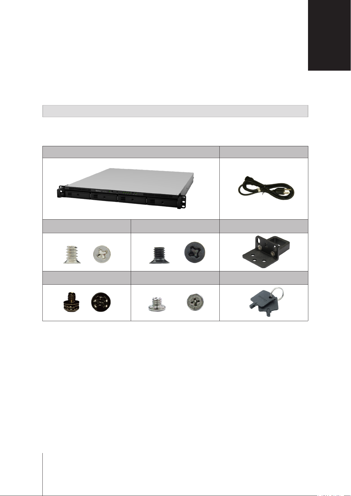
Thank you for purchasing this Synology product! Before setting up your new RackStation, please check the
package contents to verify that you have received the items below. Also, make sure to read the safety instructions
carefully to avoid harming yourself or damaging your RackStation.
Note:
All images below are for illustrative purposes only, and may dier from the actual product.
Package Contents
Main unit x 1 AC power cord x 2
1
Screws for 3.5” drives
x 20
Rack mount kit screws
x 8
Screws for 2.5” drives
x 20
Screws for M. 2 drives
x 3
Rack mount kit
x 2
Drive tray key
x 2
3
3
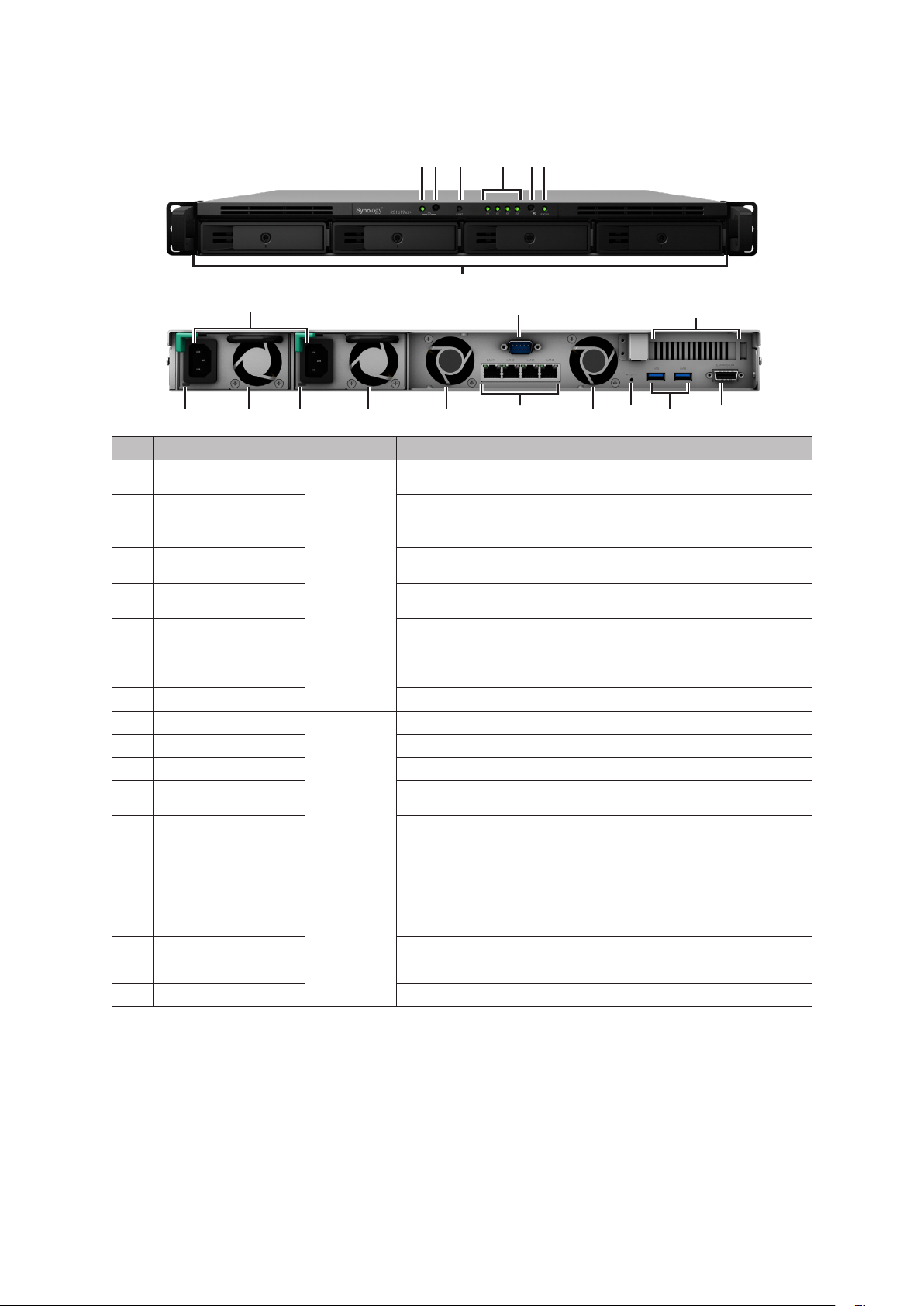
Synology RackStation at a Glance
6
1
52 3 4
7
9 14
8
916 9 916
10
12
No. Article Name Location Description
1
2
3
4
5
6
7
8
9
10
11
12
13
14
15
16
Power Indicator
Power Button
Alert Indicator
Front
Drive Status Indicator
Beep O Button
Status Indicator
Drive Tray Install drives here.
Power Port
Fan Disposes of excess heat and cools the system.
Console Port For manufacturing use only.
PCI Express
Expansion Slot
LAN Port Connect network cables here.
Back
RESET Button
USB 3.0 Port Connect external drives or other USB devices to the RackStation here.
Expansion Port Connect Synology Expansion Unit2 to the RackStation here.
Redundant Power LED Displays the status of redundant powers supplies.
Displays power status of the RackStation. For more information, see
"Appendix B: LED Indicator Table".
1. Press to power on the RackStation.
2. To power o the RackStation, press and hold until you hear a beep
sound and the Power LED starts blinking.
Displays warnings regarding fan or temperature. For more information,
see "Appendix B: LED Indicator Table".
Displays the status of drives. For more information, see "Appendix B:
LED Indicator Table".
Press to deactivate the beeping sound that is emitted when a malfunction
occurs.
Displays the status of the system. For more information, see "Appendix B:
LED Indicator Table".
Connect power cords here to supply power to your RackStation.
Supports one PCIe x8 slot (x4 link) add-on card.
1. Press and hold until you hear a beep sound to restore the default IP
address, DNS server, and password for the
2. Press and hold until you hear a beep sound, then press and hold
again until you hear three beep sounds to return the RackStation
to “Not Installed” status so that DiskStation Manager (DSM) can be
reinstalled.
13
admin
11
15
account.
1
1
You can keep the current admin password unchanged by ticking the "Keep current admin password unchanged" checkbox in DSM Control Panel >
Update & Restore > Reset.
2
For more information about Synology Expansion Unit supported by your RackStation, please visit
www.synology.com
.
4 Chapter 1: Before You Start
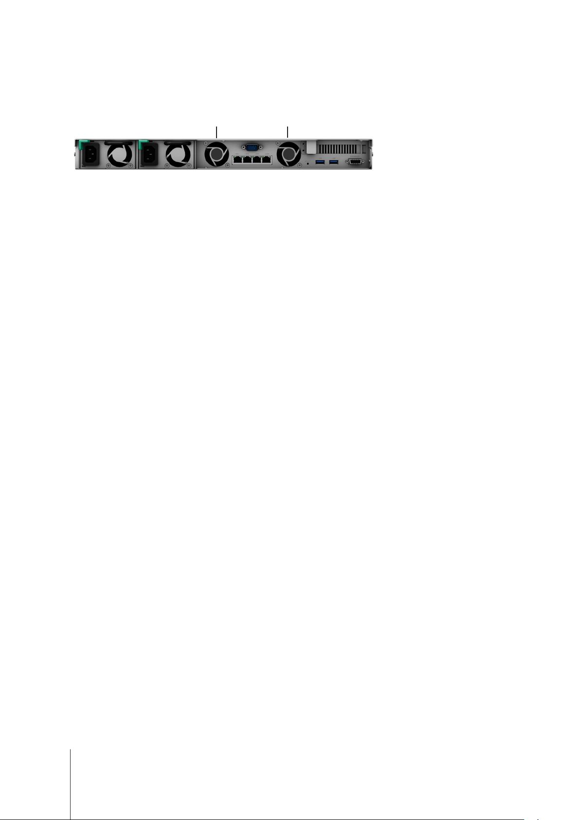
System Fans
If any fan failure occurs, please refer to the images below to locate the failed fan(s) indicated in DSM. The fans
are numbered as below:
1
To replace the failed fan(s), please contact Synology Technical Support at
technical assistance.
2
www.synology.com/support
for
5 Chapter 1: Before You Start
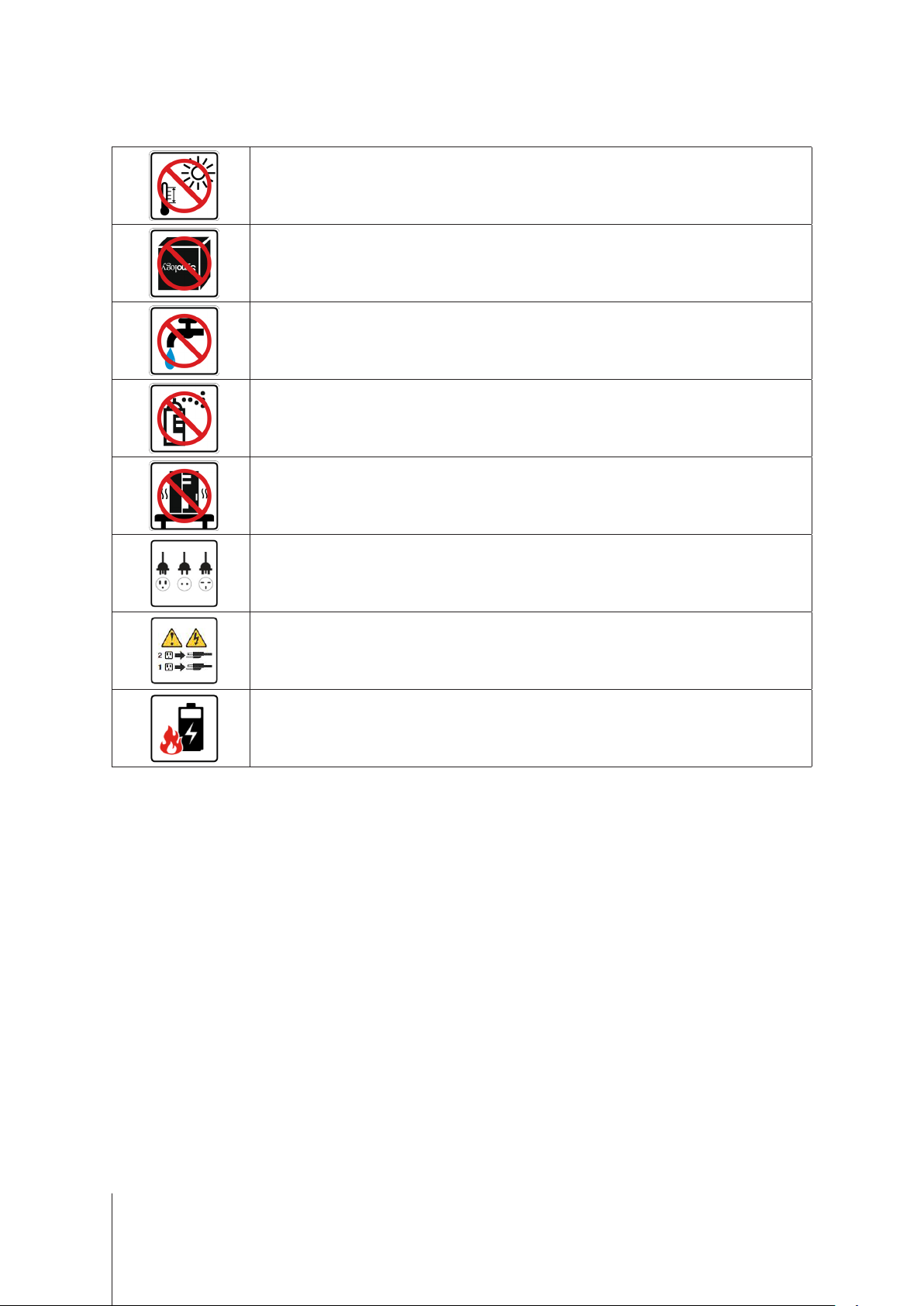
Safety Instructions
Keep away from direct sunlight and away from chemicals. Make sure the environment does not
experience abrupt changes in temperature or humidity.
Place the product right side up at all times.
Do not place near any liquids.
Before cleaning, unplug the power cord. Wipe with damp paper towels. Do not use chemical or
aerosol cleaners.
To prevent the unit from falling over, do not place on carts or any unstable surfaces.
The power cord must plug in to the correct supply voltage. Make sure that the supplied AC voltage is
correct and stable.
To remove all electrical current from the device, ensure that all power cords are disconnected from
the power source.
Risk of explosion if battery is replaced with an incorrect one. Dispose used batteries appropriately.
6
Chapter 1: Before You Start

Chapter
Hardware Setup
Tools and Parts for Drive Installation
• A screwdriver.
• At least one 3.5” or 2.5” SATA drive (please visit
Warning:
back up important data before installation.
If you install a drive that contains data, the system will format the drive and erase all existing data. Please
Install Rack mounts
Fix the two rack mount kits on both sides with the screws provided.
www.synology.com
2
for compatible drive models.)
Install Drives
1
Pull the drive tray handle outwards to remove the tray.
2
Load drives into the drive trays.
For 3.5” drives:
•
four spots indicated below to secure the drive.
Place the drive in the drive tray. Turn the tray upside down and tighten the screws into the
7
 Loading...