

Page 1
as s em b ly m a n u a l – 9 9 9 –3 0 4
Page 2
Congratulations on your purchase of the Synergy N5c radio controlled helicopter kit. The Synergy N5c was
designed and developed by Botos Design & Distribution Inc.. The design of the Synergy N5c emerged from
many years of experience in the hobby including design, research & development, and last but not least
as a world class pilot who truly enjoys this wonderful hobby.
This radio controlled helicopter is NOT A TOY. It is a sophisticated piece of equipment and was designed
and intended for hobby use only. If not properly assembled, maintained or operated, it is capable of
causing property damage and bodily harm to both the operator and/or spectators. Botos Design &
Distribution Inc., its affiliates and its authorized distributors assume no liability for damage that could occur
from the assembly or use/misuse of this product. If you are new to the hobby we strongly recommend
seeking the help and advice from an experienced modeler.
Operating a model helicopter requires a high degree of diligence and skill. If you are new to the hobby, it
is best to seek help and guidance from experienced radio controlled helicopter pilots. This will both greatly
speed up the learning process and make it much safer for you.
For those pilots who will be operating their Synergy N5c in the United States, we strongly recommend
joining the AMA. The AMA is a non-profit organization that provides services to the model aircraft pilots. As
an AMA member, you will receive a monthly magazine entitled Model Aviation and most importantly a
liability insurance plan to cover against possible accident or injury. All AMA charter aircraft clubs require
individuals to hold a current AMA sporting license prior to operation of their models
For further information, you can contact the AMA at
Academy if Model Aeronautics
5151 East Memorial Drive
Muncie, IN 47302
(317) 287-1256
Page 3
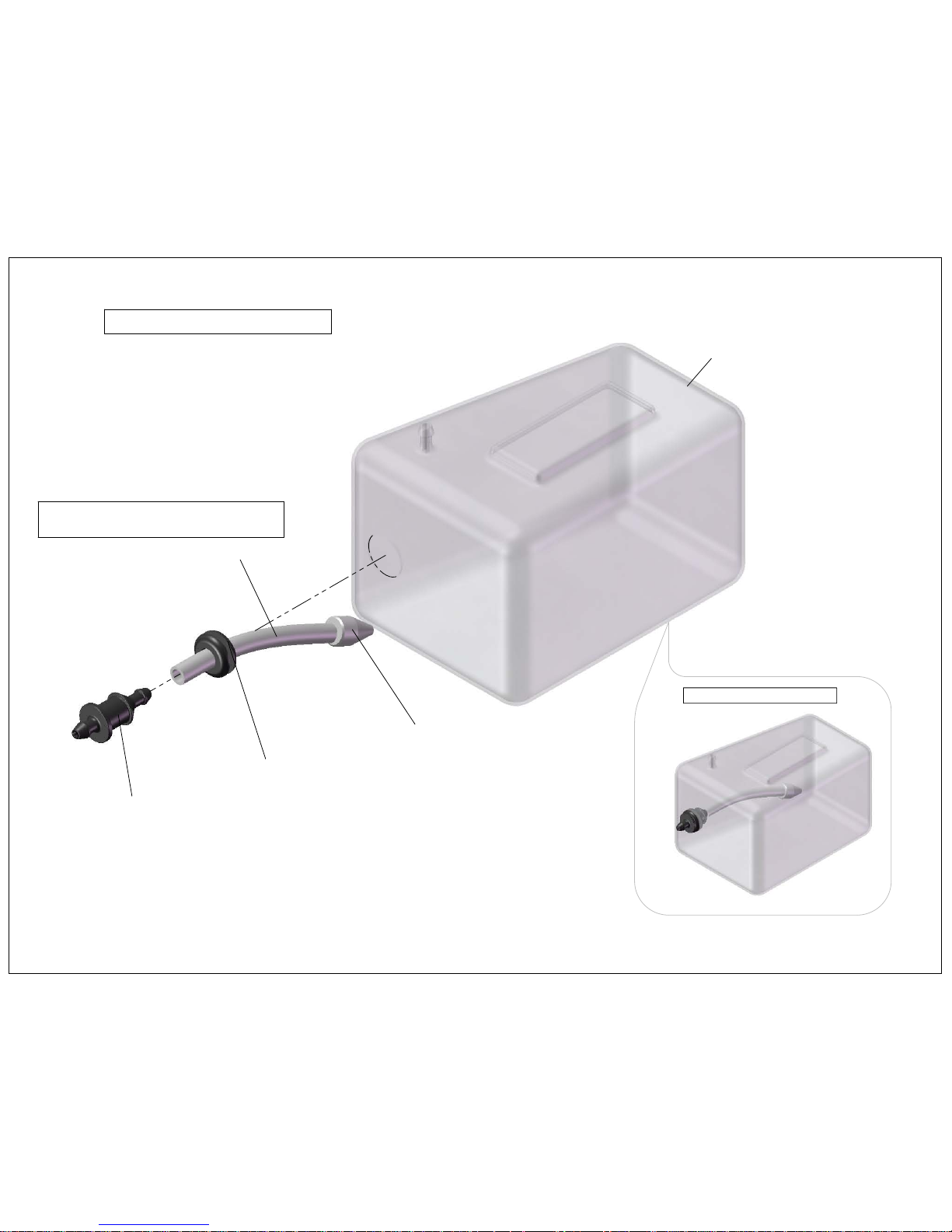
610-330 Fuel Tank
110-332 Fuel Clunk
110-333 Fuel Clunk Tubing
110-331 Fuel Tank Stopper
106-810 Fuel Tank Stopper Grommet
Complete Fuel Tank
Fuel Tank Assembly
Page 1
Trim fuel tubing to 65mm or desired length
so that fuel clunk reaches to the rear of
fuel tank.
Page 4
Page 2
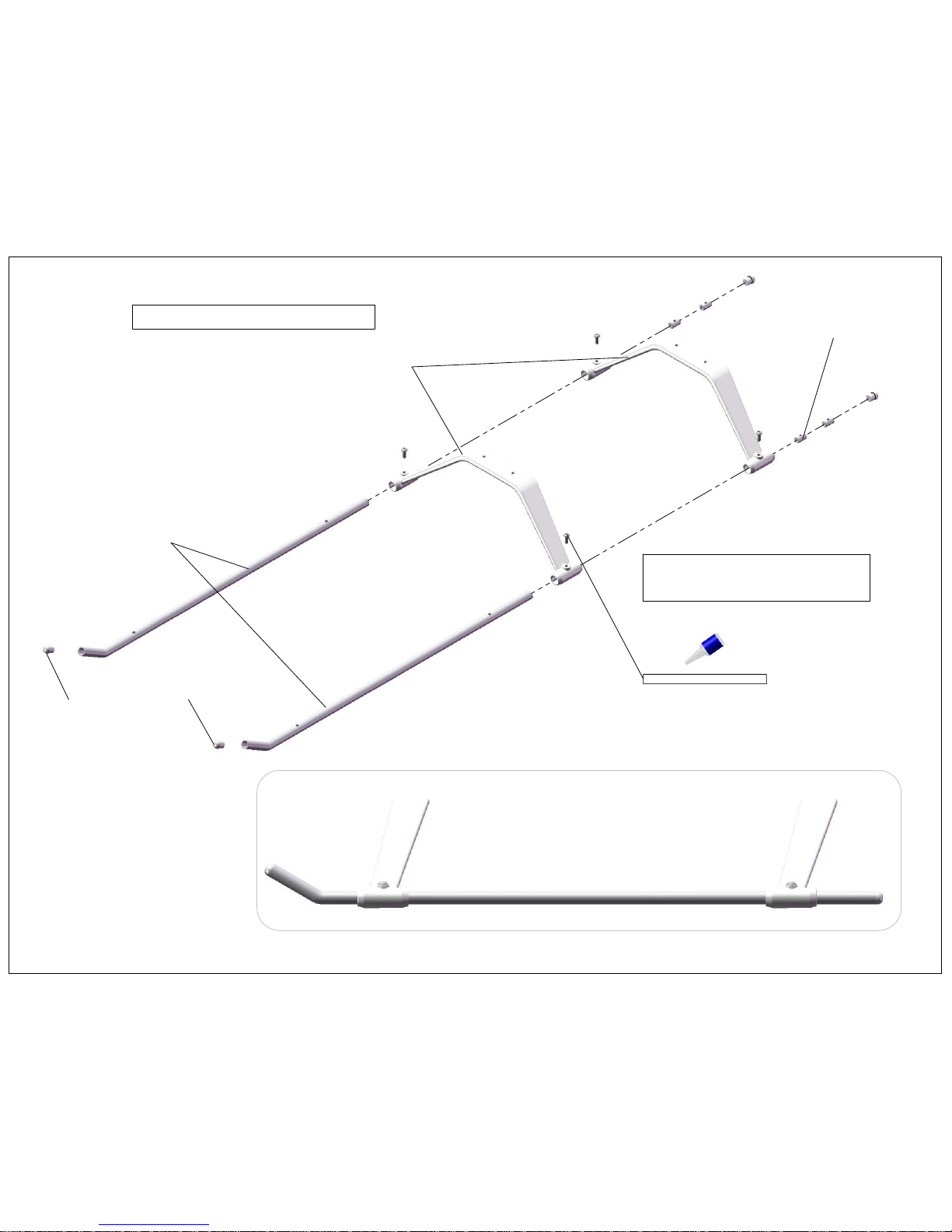
Landing Gear Assembly
Complete Landing Gear
101-308 M3x8 Button Head
610-324 Landing Gear Strut
610-322 Skid Tube Lock x4
610-321 Skid Tube
Screw Skid Tube Lock Down
on to ybar then secure within
Skid Tube
106-966 Skid Tube Plug x4
Page 5
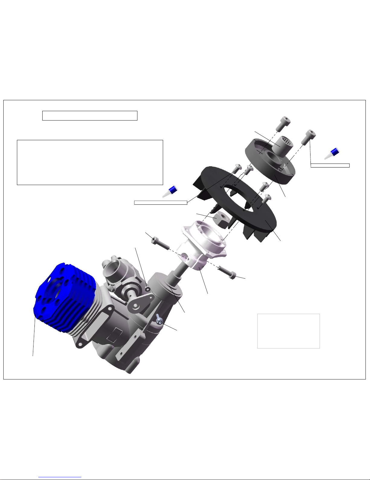
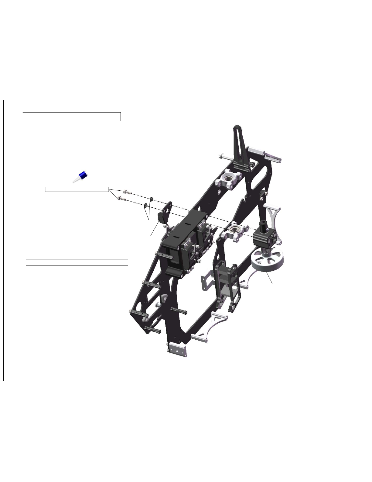
Engine Clutch Assembly
Page 3
50 - 55 Sized Engine(not included)
610-1172 Fan Hub
100-312 M3x12 Socket Head
100-312 M3x12 Socket Head
Engine Nut(not included) See Note*
Engine Washer(not included)
610-171 Cooling Fan
101-306 M3x6 Button Head x4
610-160 Clutch
108-110 8x12x12 One Way Clutch
M4x8 Socket Head x2
107-104 2mm Pivot Ball Long
100-252 M2 Nylock Nut
(Factory Installed)
Fan Hub install note- Important!
1. Slide Fan Hub on to crank shaft then take up
end play with engine nut.(engine washer manditory!)
2. Tighten down pinch bolts evenly.
3. Insert crank locking tool (not included) and
finish tightening engine nut. Do not over tighten
crank shaft nut, only snug! It is possible to distort
fan hub by over tightening.
Tested with -
- O.S. 50 Hyper
- O.S. 55HZ
- YS56
Page 6
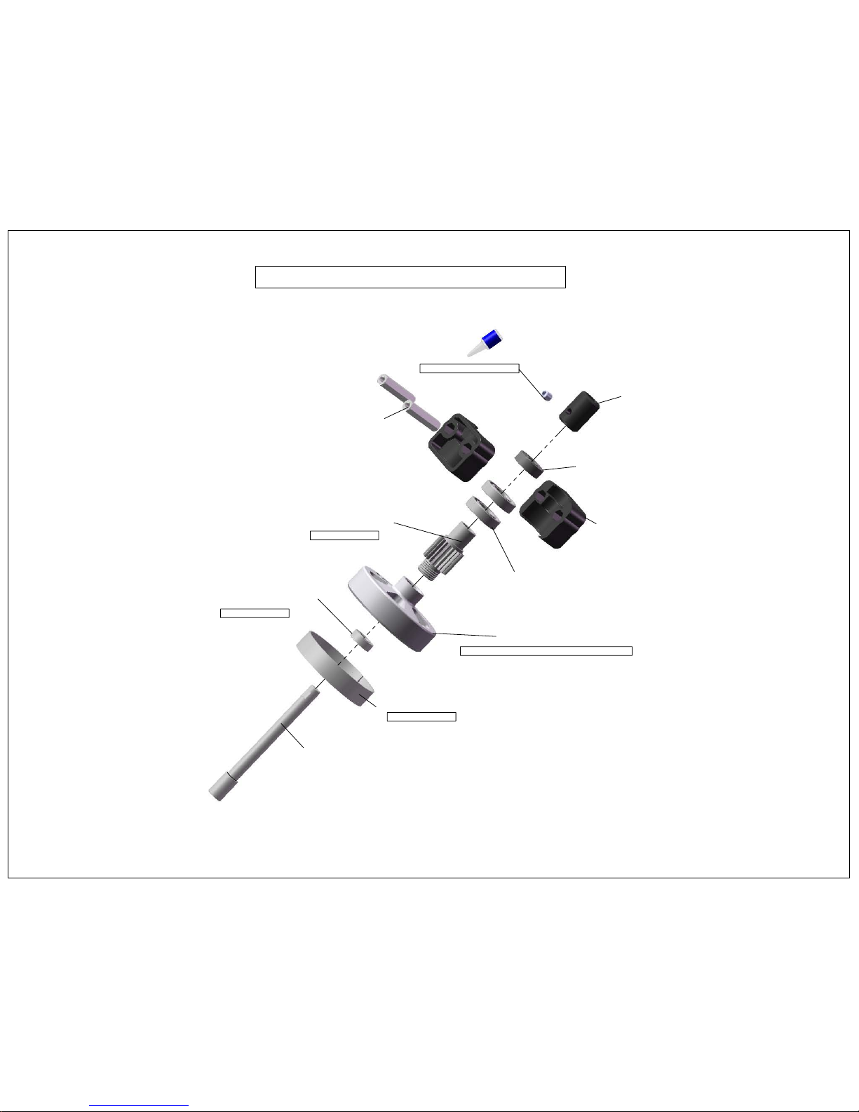
Clutch Bell & Start Shaft Assembly
Page 4
106-326 26mm Hex Standoff x2
106-955 Hex Adapter
100-466 M4x6 Set Screw
610-162 Start Shaft
108-615 6x15x5 Radial Bearing
110-155 Clutch Bearing Block
108-105 10x19x5 Radial Bearing x2
610-120 20T Pinion Gear
610-125 Clutch Bell, Lite
108-614 6x12x4 Radial Bearing
110-158 Clutch Lining
Factory Installed
Factory Installed
Factory Installed
Install governor magnet before assembly
Page 7

13.50
13.50
Servo Tray Module Assembly
Page 5
107-104 2mm Pivot Ball Long x6
610-210 Servo Tray Module
106-326 26mm Hex Stand off
Digital Servo(not included)
106-115 Servo Hold Down
100-212 M2x12 Socket Head x12
100-252 M2 Nylock Nut x6
Servo Horn
Servo Screw(included with servo)
Pivot Ball Mount Distance
For optimal performance pivot
balls should be mounted between
13.5mm from the center of the servo.
If you are running a flybarless configuation
you may want to consider 10mm for
better resolution.
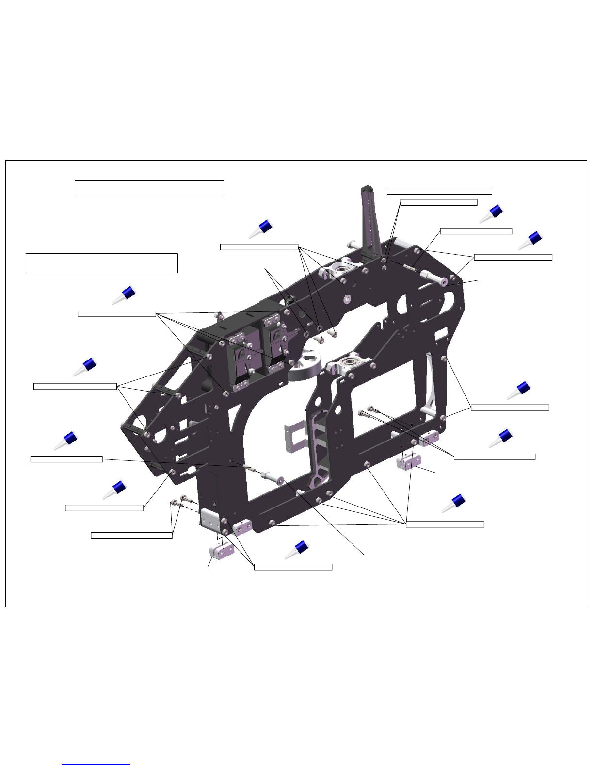
Page 8
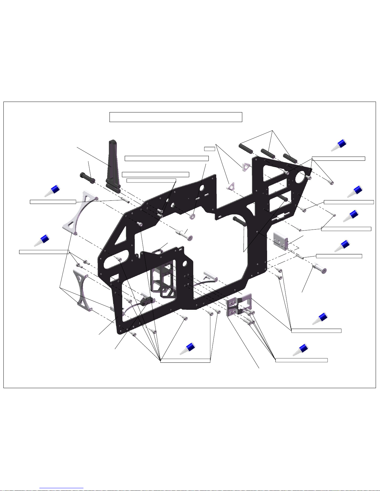
100-306 M3x6 Socket Head
100-312 M3x12 Socket Head
110-226 Tail Bell Crank Block
610-313 Arc Brace x4
610-422 Canopy Stand Off
610-133 Motor Center Block, Lite
610-312 Frame Connector Block
100-306 M3x6 Socket Head
108-484 4x8x3 Flange Bearing
120-122 Anti-Rotation Guide
610-223 3x26 Threaded Spacer
100-376 M3x16 Set Screw
101-308 M3x8 Button Head
Right Frame Support Installation
Page 6
610-311 N5C Main Frame
100-308 M3x8 Socket Head
Flange oriented on outside of frame
Do not over tighten in plastic
100-206 M2x6 Socket Head
610-123 Tail Servo Mount
610-124 N5C Front Frame Spacer
Large
100-306 M3x6 Socket Head
610-224 3x6x26 Frame Spacer
100-376 M3x16 Set Screw
610-423 Canopy Stand Off, Front
610-126 Motor Mount Lite
100-266 M2.5x6 Socket Head
Page 9
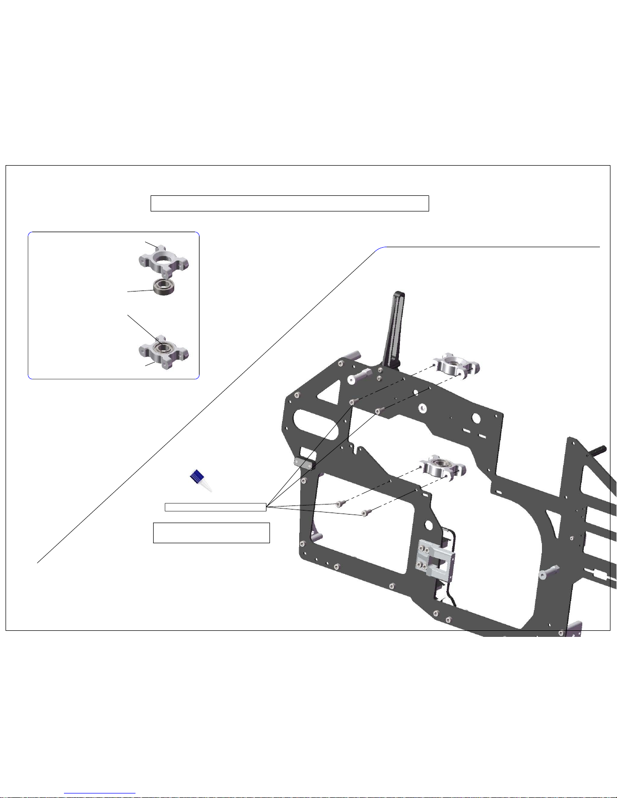
100-308 M3x8 Socket Head
Page 7
108-106 10x19x6 Radial Bearing
108-106 10x19x6 Radial Bearing
Bearing Block Assembly & Installation
510-542 Main Shaft Bearing Block, Lite
510-542 Main Shaft Bearing Block, Lite
DO NOT FULLY TIGHTEN
THESE BOLTS YET!
Page 10

Servo Tray Installation
Do not fully tighten screws!
Page 8
100-306 M3x6 Socket Head
Page 11
100-310 M3x10 Socket Head
106-930 M3 Step Washer
106-952 Governor Sensor Mount
200-404 Clutch Bell, Lite Assembly
Install governor sensor at this time.
Page 9
Clutch Stack Installation
Page 12

108-484 4x8x3 Flanged Bearing
610-323 Landing Gear Mount Block
100-310 M3x10 Socket Head
100-310 M3x10 Socket Head
Left Frame Side Assembly
610-311 Main Frame
Install Bearing Flange to outside of frame
Page 10
Step #1
610-122 Throttle Servo Mount
100-206 M2x6 Socket Head
Page 13
100-306 M3x6 Socket Head
100-306 M3x6 Socket Head
100-308 M3x8 Socket Head
610-323 Landing Gear Mount Block
610-323 Landing Gear Mount Block
100-310 M3x10 Socket Head
101-308 M3x8 Button Head
100-376 M3x16 Set Screw
610-422 Canopy Stand Off
100-306 M3x6 Socket Head
100-354 M3 Washer
100-310 M3x10 Socket Head
Do not over tighten in plastic
Do not tighten bolts completely
until next step.
Left Frame Assembly
100-306 M3x6 Socket Head
Page 11
Step #2
100-376 M3x16 Set Screw
610-423 N5C Canopy Stand Off, Front
100-306 M3x6 Socket Head
100-266 M2.5x6 Socket Head
100-306 M3x6 Socket Head
Page 14
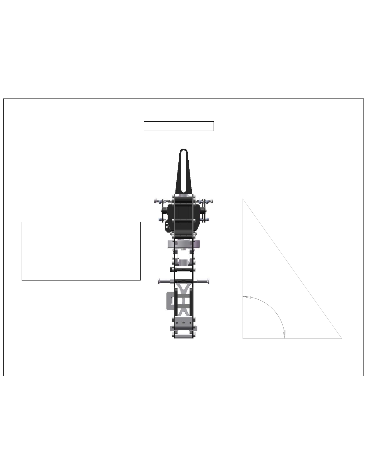
90°
Frame Alignment
With all bolts slightly loose, place
frameset on a flat surface. Slide
main shaft into main shaft bearing
blocks to make sure the main shaft
spins freely. Be sure that side frames
are 90 degrees to the flat surface.
Once you have achieved the correct
frame alignment you may finish
tightening frame bolts.
(Front view)
Page 12
Page 15
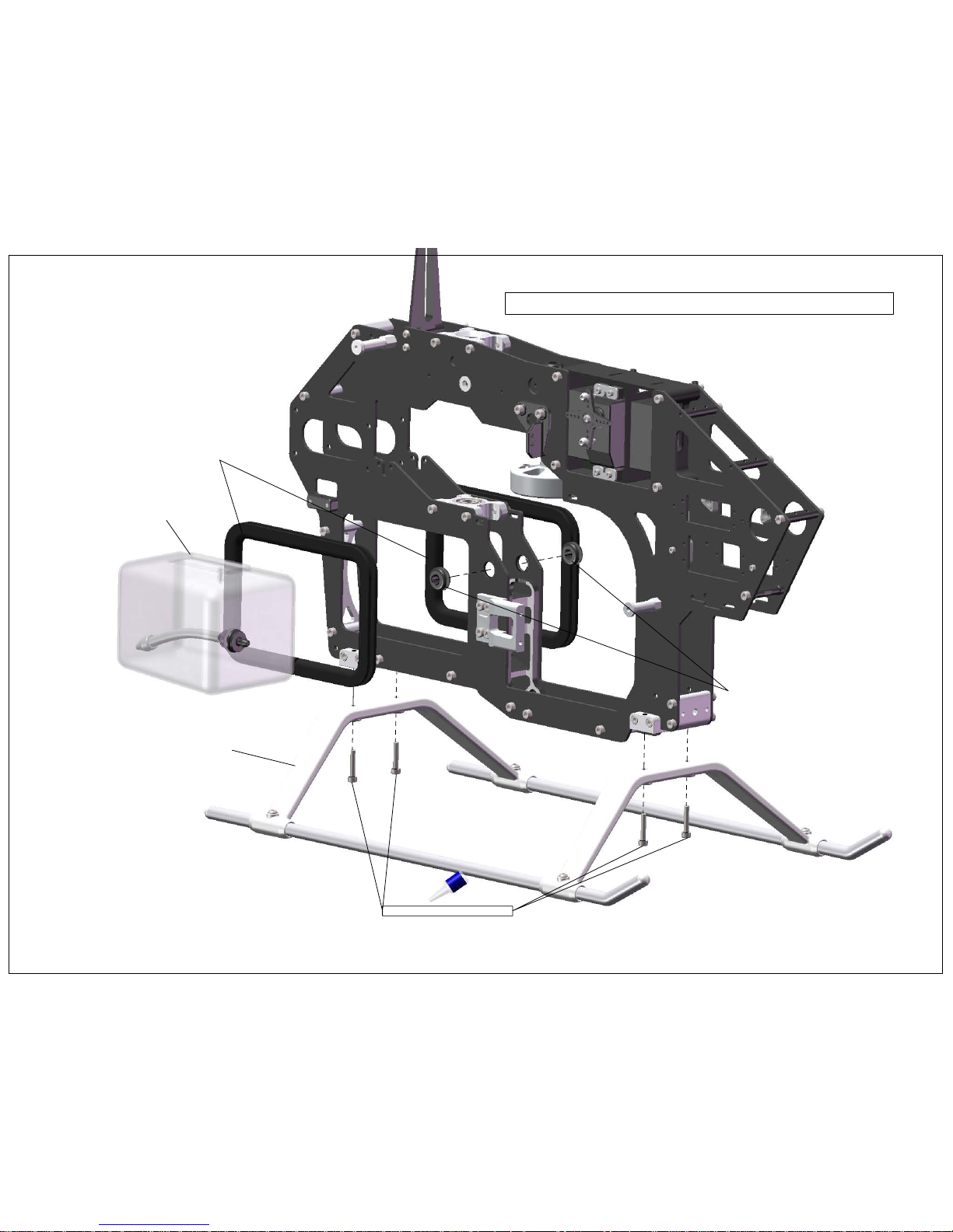
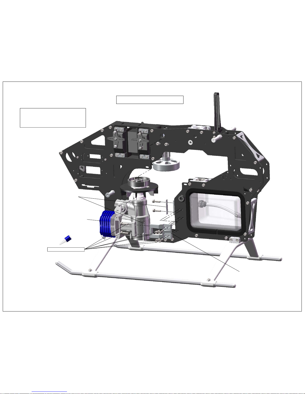
Landing Gear & Fuel Tank Installation
Fuel Tank Assembly
106-807 Tank Edge Grommet
Landing Gear Assembly
100-316 M3x16 Socket Head
Page 13
110-419 Fuel Tubing Grommet, Frame
Page 16
Engine Installation
Page 14
50-55 Size Motor
610-126 Motor Mount, Lite
M3x12 Socket Head
606-305 Motor Spacer
Note - Ensure engine is vertically
aligned with clutch stack. Start
shaft should rotate freely, and
bottom of clutch should be parallel
with bottom of clutch bell.
Page 17

610-342 Fan Shroud Right
610-343 Fan Shroud Left
100-312 M3x12 Socket Head
100-210 M2x10 Socket Head
100-312 M3X12 Socket Head
Fan Shroud Installation
Do not over tighten!
Page 15
610-224 3x6x26 Threaded Frame Spacer
Page 18

107-106 Short Pivot Ball
108-483 4x8x3 Radial Bearing
610-221Bell Crank (Aileron & Pitch)
Bell Crank Assembly
Note orientation of boss
before assembly of pivot
ball to bell crank.
101-306 M3x6 Button Head
610-228 Bell Crank Spacer
610-225 Bell Crank Shaft
107-106 Short Pivot Ball
100-464 M4x4 Flat Point Set Screw
100-464 M4x4 Flat Point Set Screw
610-222 Outside Elevator Bell Crank
610-226 Inside Elevator Bell Crank
Do not x bell cranks to shaft until
the next page where they will t into
the frame.
Page 16
X2
Page 19

Make sure set screws contact
flat spots for both inside and
outside elevator bell cranks!
Make sure there is no lateral movement
in elevator bell crank assembly. Pinch inside
bell crank to outside bell crank then tighten
set screws.
101-306 M3x6 Button Head
Cyclic Bell Crank Installation
Page 17
Note Bell Crank alignment hole
in frame for ease of correct setup.
100-464 M3x4 Flat Point Set Screw
100-464 M3x4 Flat Point Set Screw
Page 20

Tail Servo & Linkage Assembly
107-106 Pivot Ball
108-373 3x7x3 Radial
110-225 Tail Offset Bell Crank
106-301 3mm Shim
107-106 Pivot Ball
107-100 Ball Link
110-227 274mm Carbon Support Rod
107-295 295mm Tail Linkage Rod
107-100 Ball Link
109-352 3x5x2 Spacer
100-316 M3x16 Socket Head
108-373 3x7x3 Radial
Attention!
If you are using an OS55HZ motor
screw the 107-106 Pivot Ball into the
top of the Tail Offset Bell Crank. This
will allow the Tail Linkage Rod to clear
the mid-range carb needle.
100-212 M2x12 Socket Head x4
107-104 2mm Pivot Ball
100-252 2mm Nut
106-115 Servo Hold Down x2
Page 18
Page 21

Elevator Linkage
X2
Page 19
Approx.
58.50
mm
107-100 Ball Link
107-078 78mm Rod
107-100 Ball Link
Page 22

Aileron Linkage
X2
Page 20
Approx.
107
mm
107-100 Ball Link
107-100 Ball Link
107-126 126mm Rod
Page 23

Throttle Linkage
100-212 M2x12 Socket Head
Page 21
Approx.
85
mm
107-100 Ball Link
107-100 Ball Link
107-102 102mm Rod
Page 24

Pitch Servo Linkage
Page 22
Approx.
83
mm
107-100 Ball Link
107-100 Ball Link
107-102 102mm Rod
X2
Page 25

103-256 M2.5x6 Counter Sunk Screw
610-314 Carbon Fiber Radio Plate
Route all wires as you see fit
1.
Some radio gear may fit in between frames
2.
Install CF Radio Plate
3.
Install Radio Gear on CF Radio Plate
4.
Radio Plate Installation
Page 23
Page 26

320-408 Spur Gear Shaft
320-407 7mm Pin for 12T Spur Gear
320-112 12t Spur Gear
108-593 5x9x3 Radial Bearing
101-308 M3x8 Button Head
101-306 M3x6 Button Head
325-101 N5c CF TT Doubler
320-406 11mm Pin for 18T Bevel Gear
320-118 18T Front Trans Bevel Gear
320-302 Bevel Gear Bearing Block
108-510 5x10x4 Radial Bearing
100-372 M3x12 Set Screw
100-354 M3 Washer
100-351 M3 Nylock Nut
108-124 12x18x4 Radial Bearing
325-301 N5c Front Mushroom Gear Bearing Block
101-306 M3x8 Button Head
101-306 M3x8 Button Head
Front Transmission Assembly
Page 24
WWW.SYNERGYRCHELICOPTERS.COM
Page 27

115-112 Main Boom Clamp, Lite
100-306 M3x6 Socket Head
100-335 M3x35 Socket Head
100-308 M3x8 Socket Head
100-340 M3x40 Socket Head
101-308 M3x8 Button Head
101-306 M3x6 Button Head
Front Transmission Install
Page 25
WWW.SYNERGYRCHELICOPTERS.COM
Page 28

320-504 O-Ring
320-503 Torque Tube Bearing Housing
108-814 8x14x4 Radial Bearing
320-502 Torque Tube End
100-212 M2x12 Socket Head
100-252 M2 Nylock Nut
305-601 Torque Tube 705mm
Torque Tube Assembly
IMPORTANT! - Secure Torque Tube End with Red Loctite!
220mm
8 1/2 Inches
220mm
8 1/2 Inches
Secure bearing to Torque Tube with Red Loctite or CA
Bearing must be installed before Torque Tube end as the
bearing will not slide over the Torque Tube End.
Page 26
WWW.SYNERGYRCHELICOPTERS.COM
Page 29

Torque Tube Assembly (Page 32)
115-114 Tail Control Guide
610-128 Boom Support Clamp, Lite
115-114 Tail Control Guide
305-600 Stretch Tail Boom
100-312 M3x12 Socket Head
Note - CA May be required to
secure Tail Control Guide to Tail Boom
Tail Boom Assembly
Page 27
WWW.SYNERGYRCHELICOPTERS.COM
Page 30

305-303 Boom Support Rod
115-119 Boom Support End
115-119 Boom Support End
Notes -
1. Use Epoxy or JBWeld
2. Ensure ends are in alignment while glue sets
Top - attaches to boom clamp
Bottom - attaches to frames
Sand Ends Lightly Before
applying glue!
Sand Ends lightly before
applying glue!
Boom Support Assembly
109-345 3x4x5 Brass Spacer
Page 28
WWW.SYNERGYRCHELICOPTERS.COM
Page 31

107-100 Ball Link
305-311 Tail Push Rod End
106-965 Tail Push Rod Sleeve (Teflon Shrink Tubing)
305-602 Tail Control Rod 640mm
IMPORTANT! - Tail Control Rod End must be secured with
high quality glue such as JB Weld. We highly recommend
long curing formulas for the best results. Do not use CA for
this application! You will encounter failures!
Note - Lightly sand carbon tail
control rod prior to securing with
JB Weld!
Note - Tail push rod ends will slide through
tail control guides.
Tail Control Rod Assembly
Page 29
WWW.SYNERGYRCHELICOPTERS.COM
Page 32

101-412 M4x12 Button Head
100-330 M3x30 Socket Head
100-354 M3 Washer
610-121 Boom Support Spacer
610-223 3x26 Spacer
Boom and Support Install
Page 30
WWW.SYNERGYRCHELICOPTERS.COM
Page 33

100-306 M3x6 Socket Head
100-354 M3 Washer
108-503 5x10x3 Radial
106-501 5mm Shim
Small OD Small ID
Large ID Large OD
Ball Race
515-525 Tail Blade Grip
108-503 5x10x3 Radial
107-106 Pivot Ball
108-511 5x10x4 Thrust Bearing
IMPORTANT! - Apply Grease to Thrust Bearing Ball Race
615-324 Tail Rotor Hub (for 6mm shaft)
Tail Rotor Hub Assembly
Page 31
WWW.SYNERGYRCHELICOPTERS.COM
Page 34

Pitch Slider Assembly
615-319 Tail Pitch Slider Bushing (for 6mm shaft)
108-812 8x12x2.5 Radial Bearing
107-103 2mm Pivot Ball Short
115-319 Tail Bearing Ring
108-812 8x12x2.5 Radial Bearing
115-322 Tail Pitch Link
106-813 Tail Slider Lock Ring
606-921 Tail Pitch Link Pin
506-920 E-Ring
115-321 Pitch Plate
Use Medium CA to secure 2mm pivot ball
1. After installing lock ring be sure that the
radial bearings do not have lateral load
on them. Adjust lock ring as needed to
ensure smooth operation.
2. Secure lock ring with CA or Epoxy
Red Loctite Tail Pitch Slider to Tail
Pitch Plate for extra security.
Page 32
Page 35

305-309 E5 Tail Box
108-124 12x18x4 Radial Bearing
320-405 Tail Box Bearing Spacer
101-306 M3x6 Button Head
108-613 6x13x5 Raidal Bearing
305-307 E5 Output Shaft Spacer
615-124 Tail Output Shaft 6mm
305-308 E5 Tail Box Spacer
305-618 E5 18T Mushroom Tail Bevel Gear
305-518 E5 18T Tail Bevel Gear
305-304 E5 Vertical Tail Fin CF
305-305 E5 Tail Box Plate Left
305-306 Tail Box Plate Right
108-613 6x13x5 Radial Bearing
101-306 M3x6 Button Head
100-325 M3x25 Socket Head
100-306 M3x6 Socket Head
100-366 M3x6 Set Screw
Tail Box Assembly
Page 33
WWW.SYNERGYRCHELICOPTERS.COM
108-124 12x18x4 Radial Bearing
320-406 11mm Pin for 18T Bevel Gear
Page 36

100-351 M3 nylock Nut
305-310 E5 Tail Lever Mount
101-308 M3x8 Button Head
106-301 M3 Shim
108-373 3x7x3 Radial Bearing
109-355 3x5x5 Brass Spacer
Tail Rotor Bell Crank
108-373 3x7x3 Radial Bearing
100-330 M3x30 Socket Head
107-104 2mm Pivot Ball
100-251 M2 Nut
Tail Rotor Bell Crank Assembly
Page 34
WWW.SYNERGYRCHELICOPTERS.COM
Page 37

IMPORTANT!!!
Note orientation of tail blade grips. The tail
will rotate clockwise. The tail blade grips
should lead with the pivot ball at the leading
edge of the tail blade. This does not affect the
performance off the tail rotor in any way.
IMPORTANT!!!
Check left and right tail rotor direction
as well as tail gyro correction direction
after assembly is completed.
Completed Tail Box Assembly
Existing Tail Pitch Slider Assembly (Not Included)
Existing Tail Hub Assembly (Not Included)
Tail Box Completion
Page 35
WWW.SYNERGYRCHELICOPTERS.COM
Page 38

Tail Box Install
Slide tail box assembly on to tail boom.
Ensure torque tube is aligned with mushroom
bevel gear.
IMPORTANT!
If you wish to use boom pinning feature
you must drill 3mm hole! Follow these steps.
1. Install Tail Box
2. Ensure Tail Box is vertical
3. Mark drill location
4. Remove tail box and torque tube
5. Drill 3mm hole at marked location
101-306 M3x6 Button Head
Page 36
WWW.SYNERGYRCHELICOPTERS.COM
Page 39

Auto Hub Bronze Bushing
Auto Hub
One Way Clutch Bearing
Auto Hub Bronze Bushing
DO NOT USE GREASE ON ONE-WAY!!
USE LIGHT OIL SUCH AS TRIFLOW!
Auto Hub Assembly
200-407 - Auto Hub Assembly
Important - Bronze bushings must be secured
with green or red loctite!
Note - By design the auto hub is symetrical so it can
be used in both orientations. The One-Way Clutch Bearing
can be pressed into the Auto Hub in any direction. Please
pay attention to motor direction and insert auto hub sleeve
in the correct orientation.
Important - Bronze bushings must be secured
with green or red loctite!
Page 37
WWW.SYNERGYRCHELICOPTERS.COM
Page 40

320-410 Spur Gear Hub
320-154 54T Spur Gear
103-256 M2.5x6 Cross Recess
DO NOT OVER TIGHTEN!
Spur Gear Hub Assembly
Page 38
WWW.SYNERGYRCHELICOPTERS.COM
Page 41

Spur Gear Hub Assembly (from page 38)
610-147 Auto Hub Sleeve
610-151 Delrin Shim
200-407 Auto Hub (Factory Assembled)
610-170 Main Gear
101-308 M3x8 Button Head
610-151 Delrin Shim
Note - By design the auto hub is symetrical so it can
be used in both orientations. The One-Way Clutch Bearing
can be pressed into the Auto Hub in any direction. Please
pay attention to motor direction and insert auto hub sleeve
in the correct orientation.
Main Transmission Assembly
Page 39
WWW.SYNERGYRCHELICOPTERS.COM
Page 42

Main Transmission Install
100-351 M3 Nylock Nut
610-410 N5c Main Shaft TT
610-150 Main Shaft Pinch Collar
320-411 Jesus Bolt Collar
100-325A M3x25 Special Bolt
100-320A M3x20 Special Bolt
100-261 M2x10 Socket Head
IMPORTANT! Boss on Jesus bolt collar should be facing
down! Failure to orient boss correctly will
result in excessive verticle movement in the
main shaft
IMPORTANT!
Pinch collar has a boss which should
be oriented facing up against the
inner race of the main shaft bearing.
IMPORTANT!
- Do not over tighten
shouldered bolts. This will distort auto
hub sleeve which will cause auto hub
problems.
Page 40
WWW.SYNERGYRCHELICOPTERS.COM
Page 43

Swash Plate Assembly
107-108 Pivot Ball Long x3
107-106 Pivot Ball x4
108-373 3x7x3 Radial Bearing
100-316 M3x16 Socket Head
109-352 3x5x2 Brass Spacer
100-312 M3x12 Socket Head
100-364 M3x4 Set Screw
200-401 Swash Plate Assembly
WWW.SYNERGYRCHELICOPTERS.COM
Page 41
Use 100-312 M3x12 Socket Head to remove
any slop that may be present in radial bearing.
Page 44

100-512 M5x12 Socket Head
100-554 M5 Washer
108-816 8x16x5 Radial Bearing
106-801 8x0.5 Washer
108-816 8x16x5 Thrust Bearing
310-144 Blade Bolt Adapter 4mm
108-816 8x16x5 Radial Bearing
106-803 8x1mm Washer
606-803 Solid Head Damper
310-144 Blade Bolt Adapter 4mm
305-201 E5 Head Block
305-205 E5 Head Axle
305-203 E5 Pitch Arm
305-204 E5 Axle Pivot
100-308 M3x8 Socket Head
100-306 M3x6 Socket Head
107-106 Pivot Ball 3x4.5mm
Small OD / Small ID
Ball Race
Large OD / Large ID
Important - Apply grease to thrust bearing ball race
305-202 E5 Blade Grip
Grease Port
Thrust Bearings can be greased by
utilizing the external "Grease Port"
Head Block and Blade Grip Assembly
Synergy Grease Port
Page 42
WWW.SYNERGYRCHELICOPTERS.COM
Page 45

Swash Follower Arm Assembly
106-301 M3 Shim
108-383 3x8x3 Radial Bearing
305-206 E5 Washout Control Arm
109-352 3x5x2 Brass Spacer
108-383 3x8x3 Radial Bearing
108-383 3x8x3 Radial Bearing
100-323 M3x23 Socket Head
100-316 M3x16 Socket Head
109-352 3x5x2 Brass Spacer
108-383 3x8x3 Radial Bearing
107-100 Ball Link
100-272 M2.5x12 Set Screw
305-207 E5 Ball Link Adapter
106-301 M3 Shim
Note - Do not tighten 100-323 bolt until the
next page. These will pinch and secure the
main shaft.
Page 43
WWW.SYNERGYRCHELICOPTERS.COM
IMPORTANT!
Remove M2.5x12 Set Screw from Ball Link Adapter
before attempting to remove M3x16 Socket Head.
The M2.5x2 Set Screw is sitting against the M3x16
bolt and will destroy the bolt threads and the Ball
Link Adapter threads if you attempt to remove the
bolt without rst removing the set screw.
Page 46

CCPM Linkage
Swash to Blade Grip Linkage
100-351 M3 Nylock Nut
100-320A M3x20 Special Bolt
Do not over tighten jesus bolt!
Tighten Pinch bolts equally
28mm
107-043 43mm Link Rod
107-100 Ball Link
107-100 Ball Link
22mm
107-100 Ball Link
107-100 Ball Link
107-043 Link Rod
Rotor Head and Swash Plate Install
Page 44
WWW.SYNERGYRCHELICOPTERS.COM
Page 47

Canopy Mounting
Canopy Mounting Tips and Tricks:
http://synergyrchelicopters.com/forum/index.php?topic=25.0
110-418 Canopy Grommet
510-425 Canopy Thumb Screw
100-316 M3x16 Socket Head
Page 45
WWW.SYNERGYRCHELICOPTERS.COM
Page 48

Main Blade Install
100-435 M4x30 Shouldered Bolt
100-451 M4 Nylock Nut
606mm Rotor Blade with 12mm - 14mm Root (Not Included)
Page 46
WWW.SYNERGYRCHELICOPTERS.COM
Page 49

96mm - 106mm Tail Blades (Not Included)
100-351 M3 Nylock Nut
100-316 M3x16 Socket Head
106-804 Tail Blade Washer
Tail Blade Install
IMPORTANT!!!
Note orientation of tail blade grips. The tail
will rotate
clockwise
. The tail blade grips
should lead with the pivot ball at the leading
edge of the tail blade. This does not affect the
performance off the tail rotor in any way.
Page 47
WWW.SYNERGYRCHELICOPTERS.COM
Page 50

258mm
Tail Rotor Diameter
Page 48
WWW.SYNERGYRCHELICOPTERS.COM
Page 51

1353.500
Main Rotor Diameter
Page 49
WWW.SYNERGYRCHELICOPTERS.COM
 Loading...