

Page 1
Page 2

Congratulations on your purchase of the Synergy E6/7 radio controlled helicopter kit. The Synergy E6/7 was
designed and developed by Botos Design & Distribution Inc.. The design of the Synergy E6/7 emerged from
many years of experience in the hobby including design, research & development, and last but not least
as a world class pilot who truly enjoys this wonderful hobby.
This radio controlled helicopter is NOT A TOY. It is a sophisticated piece of equipment, it was designed
and intended for hobby use only. If not properly assembled, maintained, and operated, it is capable of
causing property damage and bodily harm to both the operator and/or spectators. Botos Design &
Distribution Inc., its affiliates, and its authorized distributors assume no liability for damage that could occur
from the assembly or use/misuse of this product. If you are new to the hobby we strongly recommend
seeking the help and advice from an experienced modeler.
Operating a model helicopter requires a high degree of diligence and skill. If you are new to the hobby, it
is best to seek help and guidance from experienced radio controlled helicopter pilots. This will both greatly
speed up the learning process and make it much safer for you.
For those pilots who will be operating their Synergy E6/7 in the United States, we strongly recommend
joining the AMA. The AMA is a non-profit organization that provides services to the model aircraft pilots. As
an AMA member, you will receive a monthly magazine entitled Model Aviation and most importantly a
liability insurance plan to cover against a possible accident or injury. All AMA charter aircraft clubs require
individuals to hold a current AMA sporting license prior to operation of their models
For further information, you can contact the AMA at
Academy if Model Aeronautics
5151 East Memorial Drive
Muncie, IN 47302
(317) 287-1256
Page 3
Page 4
Page 5
Belt Idler Assembly
100-320 M3x20 Socket Head
610-319 Idler Brace
108-384 3x8x4 Radial Bearing
109-352 3x5x2 Brass Spacer
610-318 Belt Tension Idler
108-384 3x8x4 Radial Bearing
106-301 3x.15mm Shim
310-101 Idler Mount Bracket
A1
106-301 3x.15mm Shim
Page 6

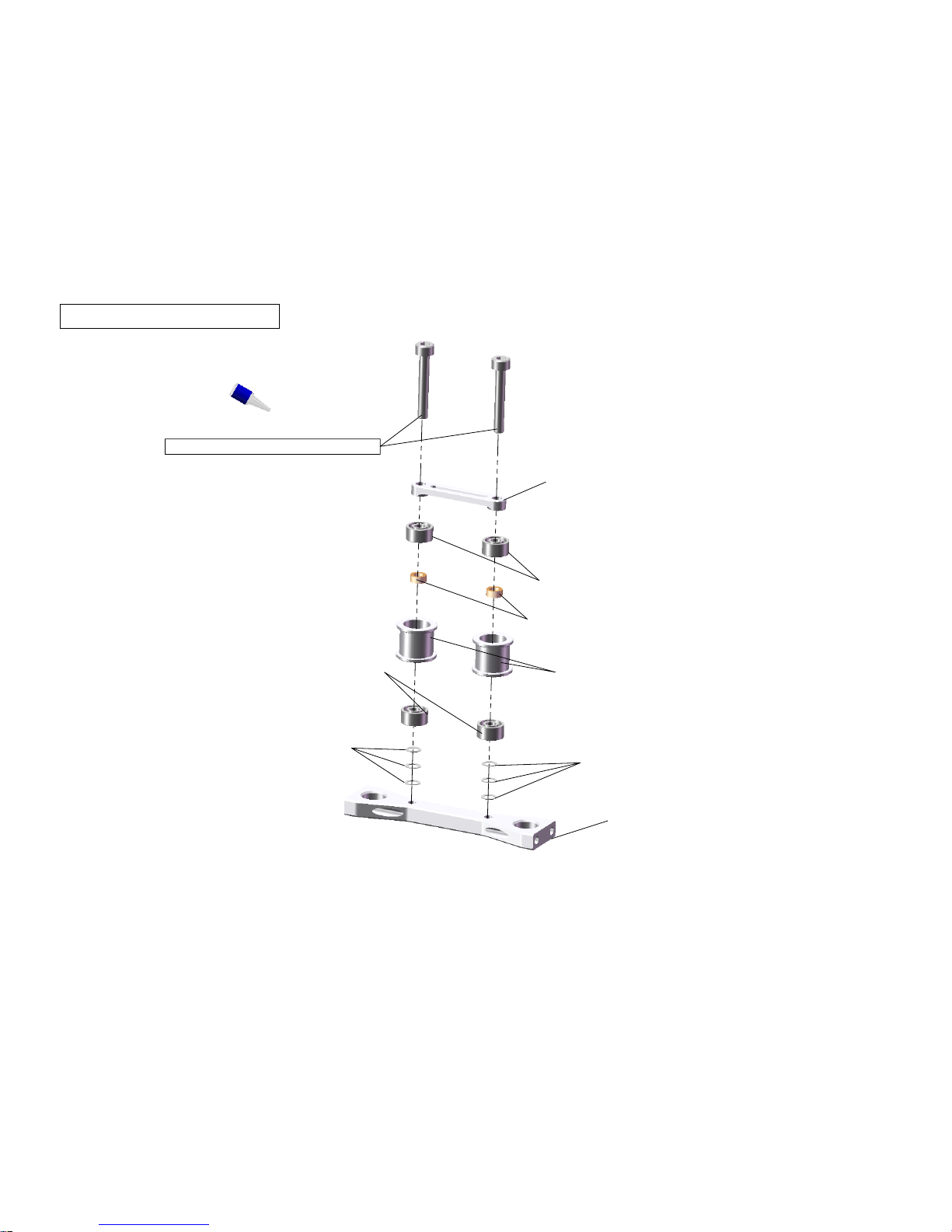
Main Shaft Bearing Blocks
A2
108-105 10x19x5 Radial Bearing
108-105 10x19x5 Radial Bearing
310-150 Main Shaft Bearing Block E6/7
310-151 Third Main Shaft Bearing Block
Important -
Keep this orientation
in mind for future reference. Make
sure bearing block and bearing
orientation is correct. Top bearing
is facing up, middle beaing is facing
down, lower bearing is facing up.
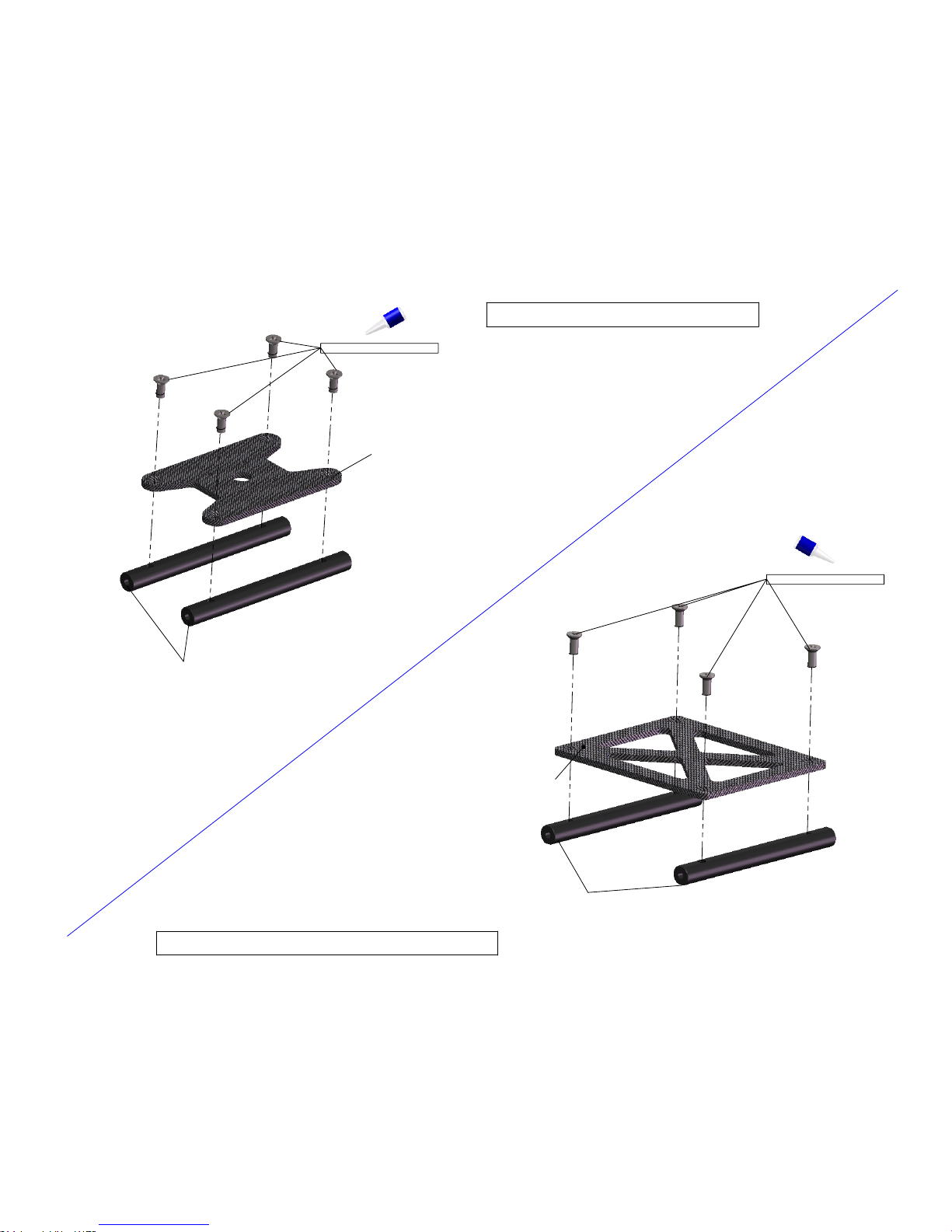
Page 7
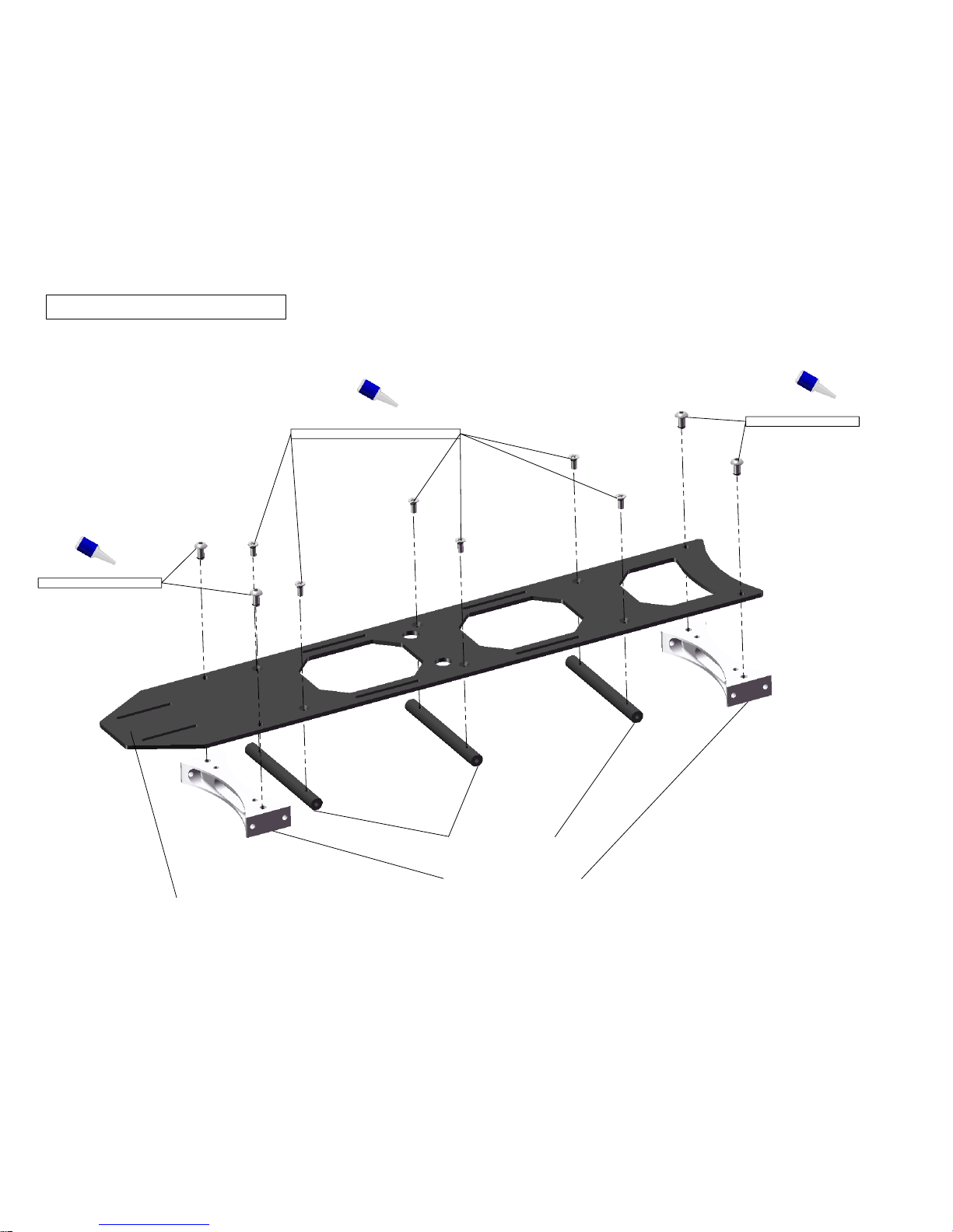
101-306 M3x6 Button Head
101-306 M3 Button Head
103-256 M2.5 Flat Head Cross Recess
310-112 Landing Gear Mount
310-110 Frame Spacer
Base Plate Assembly
A3
310-103 CF Base Plate
Page 8
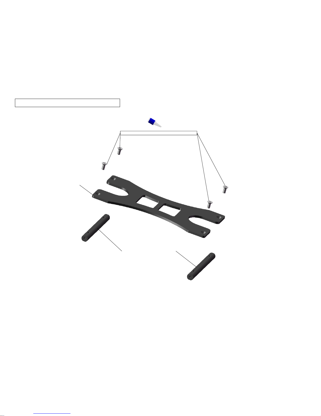
ESC Mount Plate Assembly
A4
103-256 M2.5x6 Flat Head Cross Recess
310-102 ESC Mount Plate
310-110 Frame Spacer E6/7
Page 9
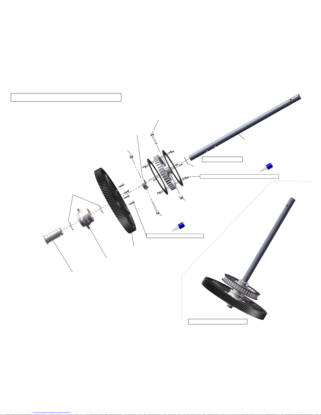
Main Transmission Assembly
A5
310-140 E Main Shaft
109-110 10mm Main Shaft Shim
100-320A M3x20 Socket Head
100-325A M3x25 Socket Head
100-351 M3 Nylock Nut
100-351 M3 Nylock Nut
101-308 M3x8 Button Head x4
610-146 Auto Hub Lock Collar
103-204 M2x4 Type I Cross Recessed x12
310-116 Helical Main Gear 116T
200-407 Auto Hub Assembly
610-147 Auto Hub Sleeve
610-151 Auto Hub Delrin Shim
Complete Transmission
Important Shim!
Page 10
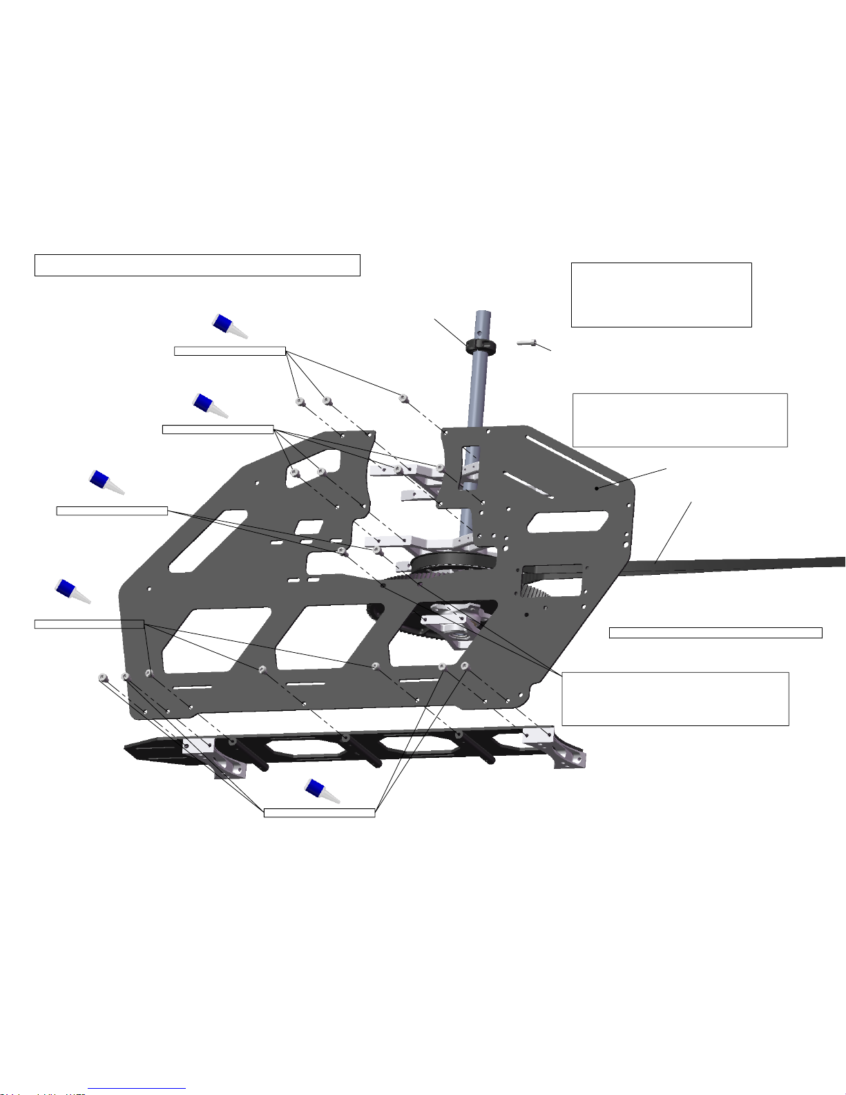
100-306 M3x6 Socket Head
100-306 M3x6 Socket Head
101-306 M3x6 Button Head
100-306 M3x6 Socket Head
100-308 M3x8 Socket Head
Transmission & Base Plate Install
A6
Important
Remember to place 10mm shim
between Main Belt Pulley and Mid Main
Shaft Bearing Block. Inner race of bearing
rides on this shim.
Important -
Lower Bearing Block holes are adjustable
for correct third bearing block alignment.
Transmission should spin freely when aligned
correctly.
610-150 Main Shaft Collar
100-261 M2.5x10 Socket Head
Note-
Do not fully tighten frame bolts yet!
615-320 E6 - 736XL
315-320 E7 - 770XL
310-311 - Main Frame E6/7
Important -
Make sure bearing
block and bearing orientation
is correct. Top bearing is facing
up, middle beaing is facing down,
lower bearing is facing up. Refer to
page A2 for correct orientation.
Page 11

Tail Servo Install
100-266 M2.5x6 Socket Head
100-261 M2.5x10 Socket Head
107-104 2mm Pivot Ball
106-115 Servo Hold Down
106-115 Servo Hold Down
100-252 2mm Nylock Nut
310-100 Tail Servo Mount
A7
Page 12
103-256 M2.5x6 Flat Head
310-104 Sensor Mount Plate
310-110 Frame Spacer E6/7
Sensor Mount Assembly
Lower Frame Brace Assembly
103-256 M2.5x6 Flat Head
310-110 Frame Spacer E6/7
310-105 CF Lower Frame Brace
A8
Page 13

Sensor Mount & Lower Frame Brace Install
101-306 M3x6 Button Head
Note
- Do not fully tighten frame bolts yet!
Reserved for Boom Support
A9
Note - Mounting sensor at this
time is an option.
Page 14

Belt Idler Assembly Installation
100-308 M3x8 Socket Head
A10
Page 15

Right Frame Side Assembly
100-306 M3x6 Socket Head
101-306 M3x6 Button Head
100-306 M3x6 Socket Head
101-306 M3x6 Button Head
100-306 M3x6 Socket Head
100-308 M3x8 Socket Head
100-308 M3x8 Socket Head
A11
310-311 CF Main Frame E6/7
Page 16

310-420 Canopy Mount E6/7
100-376 M3x16 Set Screw
100-376 M3x16 Set Screw
310-420 Canopy Mount E6/7
101-306 M3x6 Button Head
310-106 Anti-Rotation Brace E6/7
A12
Anti-Rotation Brace & Rear Canopy Mount
Page 17

90°
Main Frame Alignment
A13
Note - Ensure main shaft spins
freely within bearings. If main
shaft does not spin freely loosen
all bolts and ensure frames are
square with bearing block. Secure
all main frame bolts at this time.
Page 18

Servo Horn Assembly
100-352 M3 Nut
107-106 Pivot Ball
310-107 CF Servo Arm
Plastic Servo Arm
(Not Included)
100-252 M2 Nylock Nut
Servo Arm Screw
(Not Included)
100-206 M2x6mm Socket Head
Cyclic Servo Install
100-261 M2.5x10 Socket Head
106-115 Servo Hold Down
Note
- All three cyclic servos should
be installed at this point in time. At a
minimum the elevator servo should be
installed as it may be difficult to install
later in the assembly.
106-115 Servo Hold Down
A13
Note -
Some plastic servo arms may require
modification in order to be able to use CF Servo arms.
You may use other plastic servo arms as long as pivot
ball position is 20mm from center.
Page 19

A15
Landing Gear Assembly
Complete Landing Gear
101-308 M3x8 Button Head
610-324 Landing Gear Strut
610-322 Skid Tube Lock x4
610-321 Skid Tube
106-966 Skid Tube Plug x4
Page 20

100-312 M3x12 Socket Head
A16
Landing Gear Install
Page 21

101-306 M3x6 Button Head
310-108 CF Radio Plate
310-111 Main Boom Clamp E6/7
100-310 M3x10 Socket Head
310-111 Main Boom Clamp E6/7
Main Boom Clamp Assembly
A17
Page 22

100-308 M3x8 Socket Head x8
Main Boom Clamp Install
A18
Page 23

100-412 M4x12 Socket Head
310-130 Motor Mount 30mm
100-466 M4x6 Set Screw
Helical Pinion (14T & 15T included in kit)
Recommended Motor 12s - Hacker Turnado 470kv
10s - Hacker Turnado 580kv
Available Pinions
303-012 - 12T Helical Pinion
303-013 - 13T Helical Pinion
303-014 - 14T Helical Pinion
303-015 - 15T Helical Pinion
Brushless Motor Mounting
A19
Important!
Motor mount is designed to accept motor
with 4mm bolts and 30mm bolt pattern option.
25x3mm motor mounting was left out due to weakness
of the M3 bolts and increasing power of todays motors.
Motor shaft should be minimum of 32mm in length
outside of the motor in order to properly engage
motor shaft bearing block.
Inportant!
Pinion should rest on inner race
of lower pinion support. Failure
to configure properly will result
in premature motor bearing wear.
Note
- Synthetic grease may be used
on main gear / pinion in order to reduce
heat and improve gear interation.
Page 24

100-310 M3x10 Socket Head
310-128 Motor Mount CF Washer
310-129 Motor Shaft Support CF Washer
310-152 Motor Shaft Support Bearing Block
108-615 6x15x5 Radial Bearing(factory installed)
100-310 M3x10 Socket Head
310-129 Motor Shaft Support CF Washer
310-128 Motor Mount CF Washer
Brushless Motor Install
A20
Page 25

ESC / Front Canopy Mount
100-306 M3x6 Socket Head
100-376 M3x16 Set Screw
Electronic Speed Control(not included)
310-420 Canopy Mount E6/7
Note -
ESC of 120 amp or higher
recommended for 10S and 12S
operation.
A21
Page 26

115-114 Push Rod Guide
610-128 Boom Support Clamp, Lite
Tail Boom 615-140 - Tail Boom 775mm E6
315-140 - Tail Boom 810mm E7
Tail Push Rod
615-111 - Carbon Tail Control Rod 695mm E6
315-111 - Carbon Tail Control Rod 728mm E7
106-965 Push Rod Sleeve (Teflon Heat Shrink Tubing)
107-043 43mm Rod
107-043 43mm Rod
107-100 Ball Link
107-100 Ball Link
Boom & Push Rod Assembly
A22
Approx. 5mm
Insert 43mm threaded rod approximately 27mm into
carbon tube. Use Medium CA to glue threaded rod
into carbon rod.
Note - Space Tail Control Guides evenly.
Place the rear Tail Control Guide behind
Boom Support Clamp. CA can be used to
secure Tail Control Guides but generally
this is not needed.
Page 27

100-310 M3x10 Socket Head
101-412 M4x12 Button Head
109-345 3x4x5 Brass Spacer
100-354 M3 Washer
100-316 M3x16 Socket Head
Boom Support Assembly
Boom Installation
Feed belt through boom
1.
Slide boom forward until flush with front boom clamp
2.
Secure boom clamp bolts now, belt tension adjusted in rear
3.
Note - Use Medium CA to secure Boom Support
End to Carbon Boom Support Rod
A23
Boom Support Ends
115-119 Boom Support End
615-117 Carbon Boom Support Rod 520mm E6
315-117 Carbon Boom Support Rod 585mm E7
Page 28

100-251 M2 Nut
107-104 2mm Pivot Ball
100-320 M3x20 Socket Head
108-373 3x7x3 Radial
109-355 3x5x5 Spacer
115-316 Tail Bell Crank
108-373 3x7x3 Radial
100-351 M3 Nylock Nut
615-317 Tail Lever Mount
106-301 M3 Shim
Step #2 Tail Box Assembly
Step #1 - Tail Bell Crank Assembly
100-335 M3x35 Socket Head x5
101-306 M3x6 Button Head x4
108-616 6x13x5 Flange Bearing
610-224 3x6x26 Spacer
115-112 Main Boom Clamp, Lite
615-311 Tail Box Plate
Belt Drive Tail Box Assembly
A24
Tail Bell Crank Assembly
100-306 M3x6 Socket Head
Page 29

Belt Drive Tail Box Assembly
A25
100-306 M3x6 Socket Head
101-306 M3x6 Button Head
615-136 CF Vertical Fin
108-616 6x13x5 Flange Bearing
109-357 3x5x7 Brass Spacer
108-384 3x8x4 Radial Bearing
109-357 3x5x7 Brass Spacer
615-316 Belt Tension Idler
IMPORTANT!
Do not over tighten belt idler bolt!
Over tightening will cause bearings
inside idler to bind.
100-351 M3 Nylock Nut
Page 30

Tail Output Shaft Install
615-124 6mm Tail Output Shaft
615-314 9T Tail Pulley (for 6mm Shaft)
100-364 M3x4 Set Screw
A26
Page 31

Tail Hub Assembly
A27
100-308 M3x8 Socket Head
100-354 M3 Washer
108-503 5x10x3 Radial Bearing
106-501 5mm Shim
108-511 5x10x4 Thrust Bearing
515-525 HD Tail Blade Grip
108-503 5x10x3 Radial Bearing
107-106 Pivot Ball
615-324 HD Tail Rotor Hub
Tail Thrust Bearing Note -
- Large OD / Large ID - Inside
- Small OD/ Small ID - Outside
- Shim goes between Thrust
and Radial
GREASE THRUST BEARING INNER RACE!
DO NOT OVER TIGHTEN!
Page 32

Pitch Slider Assembly
615-319 Tail Pitch Slider Bushing (for 6mm shaft)
108-812 8x12x2.5 Radial Bearing
107-103 2mm Pivot Ball Short
115-319 Tail Bearing Ring
108-812 8x12x2.5 Radial Bearing
115-322 Tail Pitch Link
106-813 Tail Slider Lock Ring
606-921 Tail Pitch Link Pin
506-920 E-Ring
115-321 Pitch Plate
Use Medium CA to secure 2mm pivot ball
1. After installing lock ring be sure that the
radial bearings do not have lateral load
on them. Adjust lock ring as needed to
ensure smooth operation.
2. Secure lock ring with CA or Epoxy
Red Loctite Tail Pitch Slider to Tail
Pitch Plate for extra security.
A28
Page 33

100-464 M4x4 Set Screw
Tail Pitch Slider & Tail Rotor Hub Installation
A29
Size Links for free tail slider operation
100-316 M3x16 Socket Head
100-351 M3 Nylock Nut
100-351 M3 Nylock Nut
Page 34

Swash Plate Assembly
107-108 Pivot Ball Long x3
107-106 Pivot Ball x4
108-373 3x7x3 Radial Bearing
100-316 M3x16 Socket Head
109-352 3x5x2 Brass Spacer
100-312 M3x12 Socket Head
100-364 M3x4 Set Screw
200-401 Swash Plate Assembly
A30
Page 35

21.25
Servo to Swash Link
Servo to Swash Linkage
Note - Link legth is approximate,
adjust as needed.
107-100 Ball Link
107-100 Ball Link x6
107-043 43mm Rod
A31
Page 36

100-512 M5x12 Socket Head
100-554 M5 Washer
106-801 8x1mm Washer
108-816 8x16x5 Radial Bearing
108-817 8x16x5 Thrust Bearing*
Apply Grease
*Note Thrust Bearing Order
Large ID Large OD - Inside Position
Small ID Small OD - Outside Position
106-803 8x.5mm Washer
606-803 Solid Head Damper
120-114 Head Axle
107-106 Pivot Ball
100-312 M3x12 Socket Head
100-308 M3x8 Socket Head
100-306 M3x6 Socket Head
520-513 FBL Blade Grip Arm
100-312 M3x12 Socket Head
Apply Grease
Flybarless Head Assembly
Inner Swash Driver Assembly
620-111 FBL Head Block
520-514 FBL Main Blade Grip
620-211 FBL Washout Hub
106-301M3 Shim
108-383 3x8x3 Radial Bearing
620-214 FBL Washout Arm
108-383 3x8x3 Radial Bearing
100-312 M3x12 Socket Head
606-923 Washout Pin
120-214 Washout Link
108-262 2x6x2.5 Radial Bearing
506-920 E-Ring
100-308 M3x8 Socket Head
109-352 3x5x2 Brass Spacer
A32
Note - Plastic links are directional.
Pay close attention to orientation.
Page 37

Use middle hole on head block
when using stock 78mm pitch links
Upper Hole can be used with linkage
adjustment.
Align Swash Driver paralell with head
block. Adjust height of swash driver so
washout link is 90 degrees to Washout
Arm at zero degrees collective pitch.
See illustration below.
Do not make washout arm parallel
with washout base at zero degrees
pitch!
x2
107-100 Ball Link x4
Rotor Head Installation
100-320A M3x20 Socket Head
100-312 M3x12 Socket Head x2
100-351 M3 Nylock Nut
A33
107-078 78mm Rod
Approx. 61mm
107-078 78mm Rods
Correct Angle at 0 Pitch
Page 38

100-435A M4x35 Shouldered Bolt (E6)
100-535A M5x35 Shouldered Bolt (E7)
310-144 - Blade Bolt Adapter 4mm (E6)
310-145 - Blade Bolt Adapter 5mm (E7)
100-451 M4 Nylock Nut (E6)
100-551 M5 Nylock Nut (E7)
Main Blade Grip - Blade Bolts
A34
Note E6 uses 4mm blade bolts
E7 uses 5mm blade bolts
Page 39

110-418 Canopy Grommets x4
310-400 E6/7 Canopy Stock
Canopy Mounting
A35
Page 40

 Loading...