

Page 1
®
Museo
5303, 5305, 5306
Shower System Series
Operation & Maintenance Manual
Model Numbers Specification
5303
Hand Shower System
5305
Shower/Hand Shower System
5306
Tub/Shower/Hand Shower System
Options/Modifications
-1.5 1.5 gpm (5.7 L/min) flow restrictor
-2.0 2.0 gpm (7.6 L/min) flow restrictor
-BLK Polished Graphite finish
-STN Satin Nickel finish
-TRM Trim only, valve not included
Note: Append appropriate -sufx to model number.
CG
Compliance
-ASME A112.18.1/CSA B125.1
Warranty
Limited Lifetime - to the original end purchaser in
consumer/residential installations.
5 Years - for industrial/commercial installations.
Refer to www.symmons.com/warranty for complete
warranty information.
5303
Hand shower system powered by the Temptrol® pressure
balancing valve. Features adjustable stop screw to limit
handle turn, lever handle, wall connection & cradle,
exible metal hose, 2 mode hand shower with backow
prevention and standard 2.5 gpm (9.5 L/min) ow
restrictor.
5305
Shower/hand shower system powered by the Temptrol®
pressure-balancing valve. Features adjustable stop screw
to limit handle turn, separate two function diverter, lever
handle, wall connection & cradle, exible metal hose,
2 mode hand shower with backow prevention, 1 mode
showerhead and standard 2.5 gpm (9.5 L/min) ow
restrictors.
5306
Tub/shower/hand shower system powered by
the Temptrol® pressure balancing valve. Features
adjustable stop screw to limit handle turn, separate
three function diverter, lever handle, wall connection &
cradle, exible metal hose, 2 mode hand shower with
backow prevention, non-diverter tub spout and 1 mode
showerhead with standard 2.5 gpm (9.5 L/min) ow
restrictors.
Components made from metal and nonmetallic materials
plated in standard polished chrome nish.
Page 2
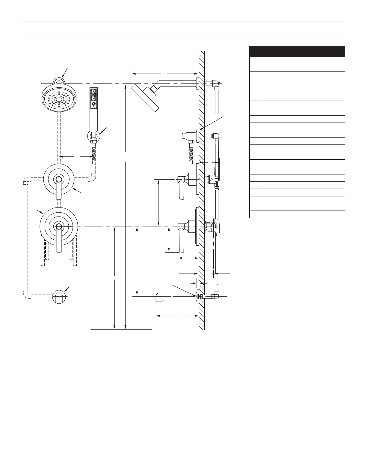
Dimensions
G
G
A
Measurements
A Ø 2", 51 mm
B 11-1/8", 283 mm
B
B
D
D
CC
F
E
E
H
H
F
J
J
I
I
C Ø 2", 51 mm
Male 1/2" IPS thread
D
E 6", 152 mm
F 77", 1956 mm
G Ø 6-1/4", 159 mm
H Ø 5", 127 mm
I Ref. 10", 254 mm
J 3-1/2", 89 mm
K Ø 2-1/4", 57 mm
L Ref. 32", 813 mm
M Ref. 12", 305 mm
N 3-1/4", 83 mm
O 3-3/4", 95 mm
P 1/2" - 14 NPT
Q 1/2", 13 mm
R
S 7-1/8", 181 mm
must protrude 3/8"
from nished wall
(Rough in)
2-3/8" ± 1/2", 60 mm ± 13 mm
N
N
O
M
M
L
L
P
K
K
Floor
Floor
Notes:
1) All dimensions measured from nominal rough-in (see R as reference).
2) Dimensions subject to change without notice.
P
O
Q
Q
S
S
R
R
2
Page 3

Parts Breakdown
A
K
F
E
D
H
G
K
F
E
I
J
G
Replacement Parts
B
C
M
N
R
L
P
Q
O
S
Item Description Part Number
A Wall Cradle T-673
B Shower Arm 532SA
C Showerhead 532SH
D
E
F
G
H
I
E
F
G
J
K Dome Cover T-666
L
M
N
O
P
Q
R Hand Shower 402W
S Tub Spout 532TS
T 60" Hose EF-02976
Notes:
1) Append -STN to part number for
Satin Nickel nish.
2) Append -BLK to part number for
Polished Graphite nish.
3) Append -1.5 or -2.0 to showerhead
or hand shower for low ow.
Plug Button
Star Washer
Handle Insert
Set Screw
Diverter Handle
Plug Button
Star Washer
Handle Insert
Set Screw
Shower Handle
Escutcheon
Mounting Screws
Mounting Plate
Escutcheon
Mounting Screws
Mounting Plate
T-667
T-665
LLD-103-NS-KIT
T-668-NS-K001
Notes:
1) Apply a bead of silicone around the perimeter of all shower trim
installed ush to the nished wall (less mounting plates and
brackets). Leave opening on bottom of escutcheons for weep hole.
2) Apply plumber tape to threaded connections as necessary.
DO NOT use plumber tape on ttings with face seal washers or
o-rings.
3) DO NOT OVERTIGHTEN ttings with face seal washers or o-rings.
Tools Required for Installation
T
Adjustable
wrench
Phillips head
screwdriver
Plumber tape
Silicone
3
Page 4

Installation
2
L
N
1
2
Note:
For valve body installation, please
see valve body installation guides.
1) Install small mounting plate (N)
to diverter valve (2DIV-BODY or
3DIV-BODY) and large mounting
plate (Q) to shower valve (4000BODY). Secure each with two
screws (M) and (P).
N
1
M
Q
1
P
3) Attach shower escutcheon (O) to
large mounting plate (Q).
O
Q
Note: Tabs should snap into place.
4) Install dome covers (K) to valves by
turning clockwise.
K
1
5)
Place handle insert (F) into handle
(H/J). Install diverter handle (H)
(5305 and 5306 only) and shower
handle (J) to valves.
J
H
2
2
H/J
Note: Handles should be facing the
6 o'clock position.
1
F
2) Attach diverter escutcheon (L) to
small mounting plate (N).
Note: Tabs should snap into place.
6) Secure handle(s) to valves using
star washer (E) and set screw (G).
Attach plug button (D) to handle(s).
1
K
2
G
1
E
D
3
4
Page 5

Installation/Operation
2
4
7) I
nstall tub spout (S) to pipe
tting. Turn clockwise to secure.
1
10) Install showerhead (C) to shower
arm (B). Turn clockwise to tighten.
B
1
Temperature Adjustment:
1) Turn shower handle
counterclockwise approximately
1/4 turn to put valve in cold
position.
S
8) I
nstall wall cradle (A) to pipe
tting. Turn clockwise to tighten.
2
1
2
A
9) Attach shower arm (B) to vertical
shower pipe. Turn clockwise to
tighten.
C
11) Attach large end of hand shower
hose (T) to hand shower wand
(R). Attach small end of hand
shower hose to wall elbow (A).
Turn clockwise to tighten.
R
2
1
T
2) Turn shower handle
counterclockwise approximately
1/2 turn to put valve in warm
position.
1
2
B
A
3) Turn shower handle
3
counterclockwise approximately
3/4 turn to put valve in hot
position.
T
5
Page 6

Operation (Diverter Control: 2DIV-BODY)
1) Cartridge is factory set to divert
to function 1.
POSITION 1
Note: Additional handle positions for same output are illustrated.
2) Turn handle to position 2 to divert
to function 2.
POSITION 2
Operation (Diverter Control: 3DIV-BODY)
1) Cartridge is factory set to divert
to function 1.
POSITION 1
2) Turn handle to position 2 to divert
to function 2.
POSITION 2
3) Turn handle to position 3 to share
functions 1 and 2.
POSITION 3
3) Turn handle to position 3 to divert
to function 3.
POSITION 3
4) Turn handle to position 4 to share
functions 2 and 3.
POSITION 4
5) Turn handle to position 5 to share
functions 1 and 3.
POSITION 5
6) Turn handle to position 6 to share
functions 1 and 2.
POSITION 6
Troubleshooting Chart
Troubleshooting Chart
Clean nished trim area with a soft
Finish is spotting.
WARNING: This product can expose you to chemicals including lead, which is known to the state of California to
cause cancer, birth defects, or other reproductive harm. For more information, go to www.P65Warnings.ca.gov.
Elements in water supply may cause
water staining on nish.
cloth using mild soap and water or a
non-abrasive cleaner and then quickly
rinse with water.
Symmons Industries, Inc. ■ 31 Brooks Drive ■ Braintree, MA 02184 ■ Phone: (800) 796-6667 ■ Fax: (800) 961-9621
Copyright © 2018 Symmons Industries, Inc. ■ symmons.com ■ gethelp@symmons.com ■ ZV-3067 REV 0 ■ 080118
 Loading...