

Page 1

Symmetricom 5087B
Wideband Distribution
Amplifier
Operations and
Maintenance Manual
Part Number 05087-13402
Revision E
November, 2010
Page 2

Notices
© Symmetricom, Inc. 2004-2010
No part of this manual may be reproduced
in any form or by any means (including
electronic storage and retrieval or translation into a foreign language) without prior
agreement and written consent from Symmetricom, Inc. as governed by United
States and international copyright laws.
Manual Part Number
05087-13402
Edition
Rev. E, November 2010
www.symmetricom.com
support@symmetricom.com
Phone:
Worldwide (Main Number)
1-408-428-7907
USA toll-free 1-888-367-7966
(1-888-FOR-SYMM)
Warranty
The material contained in this document is provided “as is,” and is
subject to being changed, without
notice, in future editions. Further,
to the maximum extent permitted
by applicable law, Symmetricom
disclaims all warranties, either
express or implied, with regard to
this manual and any information
contained herein, including but not
limited to the implied warranties of
merchantability and fitness for a
particular purpose. Symmetricom
shall not be liable for errors or for
incidental or consequential damages in connection with the furnishing, use, or performance of this
document or of any information
contained herein. Should Symmetricom and the user have a separate
written agreement with warranty
terms covering the material in this
document that conflict with these
terms, the warranty terms in the
separate agreement shall control.
Technology Licenses
The hardware and/or software described
in this document are furnished under a
license and may be used or copied only in
accordance with the terms of such license.
Restricted Rights Legend
If software is for use in the performance
of a U.S. Government prime contract or
subcontract, Software is delivered and
licensed as “Commercial computer software” as defined in DFAR 252.227-7014
(June 1995), or as a “commercial item” as
defined in FAR 2.101(a) or as “Restricted
computer software” as defined in FAR
52.227-19 (June 1987) or any equivalent
agency regulation or contract clause. Use,
duplication or disclosure of Software is
subject to Symmetricom’s standard commercial license terms, and non-DOD
Departments and Agencies of the U.S.
Government will receive no greater than
Restricted Rights as defined in FAR
52.227-19(c)(1-2) (June 1987). U.S. Government users will receive no greater than
Limited Rights as defined in FAR
52.227-14 (June 1987) or DFAR
252.227-7015 (b)(2) (November 1995), as
applicable in any technical data.
Safety Notices
CAUTION
A CAUTION notice denotes a
hazard. It calls attention to an
operating procedure, practice, or
the like that, if not correctly performed or adhered to, could result
in damage to the product or loss of
important data. Do not proceed
beyond a CAUTION notice until
the indicated conditions are fully
understood and met.
WARNING
A WARNING notice denotes a
hazard. It calls attention to an
operating procedure, practice,
or the like that, if not correctly
performed or adhered to, could
result in personal injury or
death. Do not proceed beyond a
WARNING notice until the indicated conditions are fully
understood and met.
Page 3

Contents
1Introduction
2 Installing and Setting Up the Symmetricom 5087B
Safety Requirements 6
Symbols 7
About This Manual 8
Conventions 9
Symmetricom 5087B Overview 10
Installing the Symmetricom 5087B 14
To set up the Symmetricom 5087B 14
Adjusting the Output Level 17
To adjust the output level 17
Assigning a Static IP Address 18
To assign the static IP address using the Lantronix DeviceInstaller
software 18
To assign the static IP address using Telnet 19
Cleaning 20
3 Monitoring the Symmetricom 5087B
Accessing the System 22
Checking System Status 23
Checking Alarms and Input Frequency 23
Understanding Alarm Output 24
Checking Model Number and Software Version 25
4 Troubleshooting the Symmetricom 5087B
Replacing Fuses 28
To replace a fuse 28
Verifying Operational Problems 29
Symmetricom 5087B Operations and Maintenance Manual Rev. E i
Page 4

A Specifications
B Glossary
Directives 33
Electromagnetic Compatibility 89/336/EEC 33
Safety 73/23/EEC 33
Standards 33
Electrical Specifications 34
Environmental Specifications 36
Physical Specifications 37
ii Symmetricom 5087B Operations and Maintenance Manual Rev. E
Page 5

Symmetricom 5087B Wideband Distribution Amplifier
Operations and Maintenance Manual
1
Introduction
Symbols 7
About This Manual 8
Conventions 9
Symmetricom 5087B Overview 10
Front panel 10
Rear panel 11
5
Page 6

1 Introduction
Safety Requirements
• Do not attempt to install or operate this equipment if you have not
first acquired proper training.
• Ensure that all cables are properly connected. The power cord must
be easy to remove from the back.
• Verify that input line voltage and current capacity are within
specifications before turning on the unit.
• Do not place power supply cords or other cables on top of unit or
against heatsinks.
• Operating and maintenance personnel must receive proper training
before installing or maintaining electrical equipment.
6 Symmetricom 5087B Operations and Maintenance Manual Rev. E
Page 7
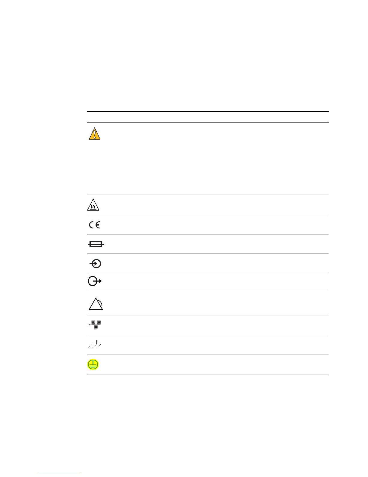
Symbols
Introduction 1
These symbols (icons) appear throughout the manual as well as on the
unit itself.
Symbol Definition
On the unit, this symbol means: Caution - Refer to User Manual.
This symbol identifies a hazard. The label next to the symbol indicates how
serious the hazard is.
Danger indicates an imminent hazard. If not avoided, the hazard will cause
death or serious injury.
War ning indicates a potential hazard. If not avoided, the hazard can cause
death, serious injury, or substantial damage to equipment.
Caution indicates a potential hazard. If not avoided, the hazard can cause
moderate injury or moderate damage to equipment.
Hot surface.
CE marking. This symbol attests compliance to applicable European
Directives.
Fuse.
Signal input.
Signal output.
Alarm signal out.
LAN port.
Chassis ground.
Earth terminal symbol: used to indicate an earth ground connection to chassis.
Symmetricom 5087B Operations and Maintenance Manual Rev. E 7
Page 8

1 Introduction
About This Manual
This manual tells you how to install, set up, monitor, and troubleshoot
the Symmetricom 5087B.
Chapter 1, “Introduction” explains symbols that appear in the manual
and on the unit as well as documentation conventions. The chapter also
briefly describes the Symmetricom 5087B.
Chapter 2, “Installing and Setting Up the Symmetricom 5087B”
contains important safety information and describes how to install the
Symmetricom 5087B, set the gain, and assign a fixed IP address.
Chapter 3, “Monitoring the Symmetricom 5087B” describes how to
monitor alarms.
Chapter 4, “Troubleshooting the Symmetricom 5087B” describes how
to replace fuses and verify operational problems.
Appendix A, “Specifications” contains the detailed specifications for
the Symmetricom 5087B.
8 Symmetricom 5087B Operations and Maintenance Manual Rev. E
Page 9

Conventions
Introduction 1
This manual uses several typographical conventions to help explain how
to use the Symmetricom 5087B.
Table 1 Conventions
Convention Definition
Bold Words i n bold show:
Italics Words i n italics show:
• Buttons and icons to click
• Menu options to select
• Commands to type
• Non-variable information displayed in response to commands
• Names of windows and dialog boxes
• Variable information displayed in response to commands
Note This symbol means the following information is a note that gives you important
information that may affect how you use the Symmetricom 5087B.
Symmetricom 5087B Operations and Maintenance Manual Rev. E 9
Page 10
1 Introduction
Symmetricom 5087B Overview
The Symmetricom 5087B Wideband Distribution Amplifier distributes
multiple copies of a precise frequency throughout a research and
development laboratory, manufacturing facility, calibration lab, or
anywhere a precise frequency standard is required.
Its input accepts 1 to 10 MHz sine waves at amplitudes of 0.3 to 3.0
Vrms and uses automatic gain control to maintain the set output level
when the input signal level varies. The Symmetricom 5087B produces
low noise copies of the input signal on each of its 12 outputs. Output
amplitude can be adjusted from 0.75 to 3 Vrms via a potentiometer
screw accessible from the front panel to compensate for cable loss.
The Symmetricom 5087B uses a 2U high, 19-inch rack-mount chassis.
An Ethernet port on the rear panel enables you to remotely monitor the
status of the input and output signals. When the unit detects a failure, it
immediately sends an alarm to the Ethernet port. The LEDs on the front
panel show the status of the input signal, each of the 12 output signals,
and the inputs.
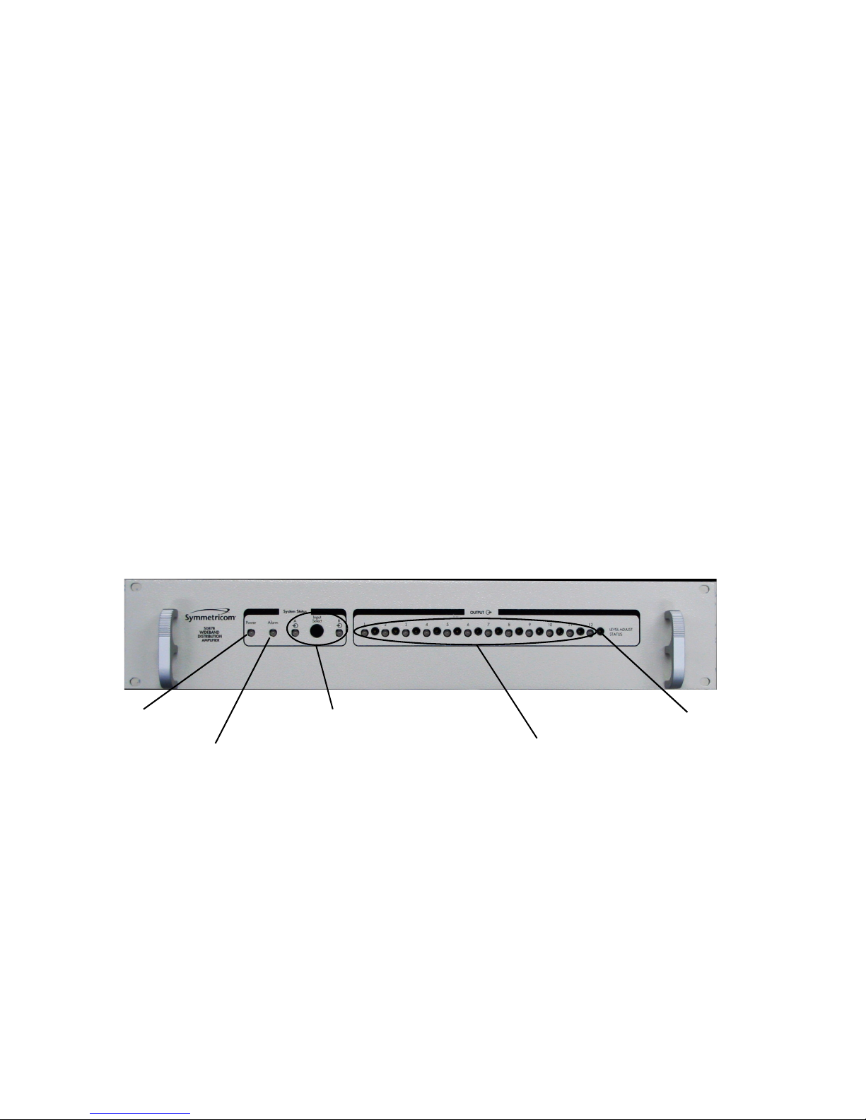
Power–Green
when power is on.
Alarm–Red when
alarm condition
Figure 1 shows the instrument’s front panel, and Figure 2 shows the rear
panel.
A, B, and Input Select–Lit
LED shows active input.
Red when not receiving an
input signal. B input is
always off.
OUTPUT–LEDs green
during normal operation of
output signals. All red when
unit has no input signal on the
active channel.
Use the
potentiometer next
to each LED to set
Figure 1 Front panel
10 Symmetricom 5087B Operations and Maintenance Manual Rev. E
Page 11

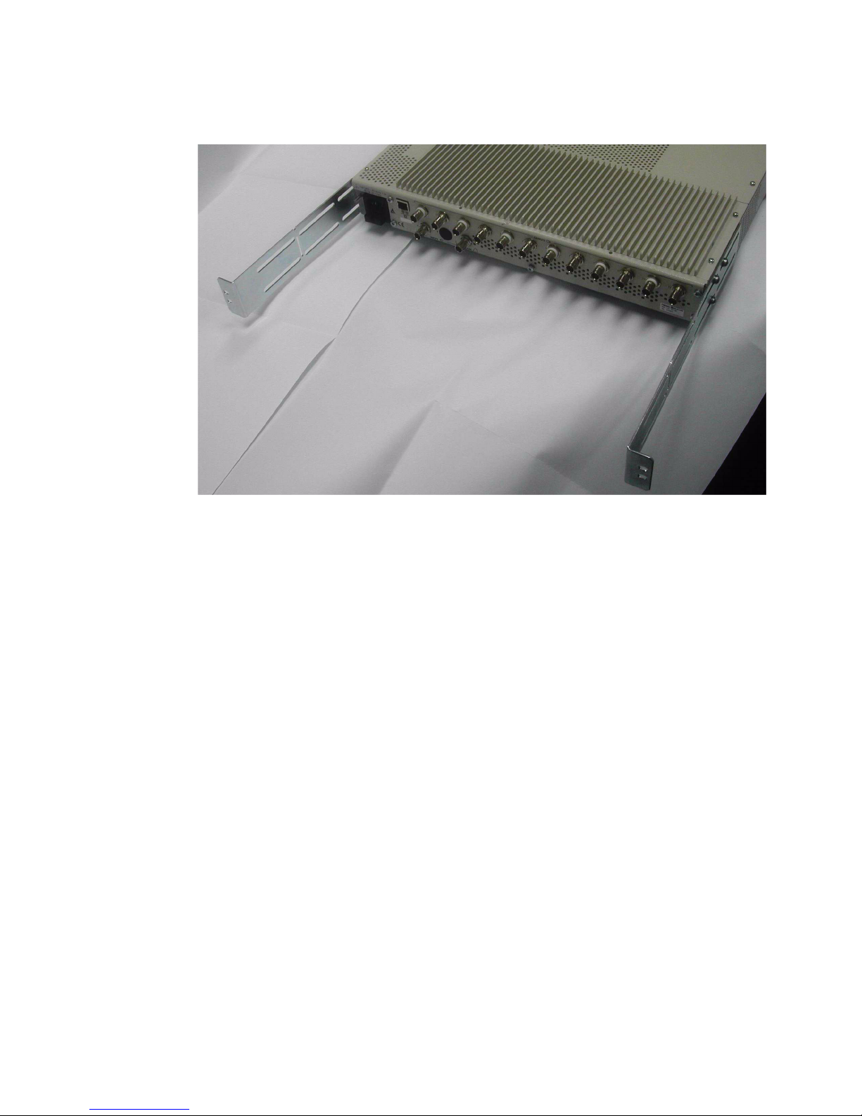
Introduction 1
AC POWER–
connector.
ETHERNET PORT–1
RJ-45 connector.
INPUT A–Connect 1
to 10 MHz source.
Figure 2 Rear panel
ALARM–Open collector
output device.
OUTPUTS–12 BNC
connectors.
Symmetricom 5087B Operations and Maintenance Manual Rev. E 11
Page 12

1 Introduction
12 Symmetricom 5087B Operations and Maintenance Manual Rev. E
Page 13

Symmetricom 5087B Wideband Distribution Amplifier
Operations and Maintenance Manual
2
Installing and Setting Up the
Symmetricom 5087B
Installing the Symmetricom 5087B 14
Adjusting the Output Level 17
Assigning a Static IP Address 18
Cleaning 20
13
Page 14

2 Installing and Setting Up the Symmetricom 5087B
Installing the Symmetricom 5087B
The Symmetricom 5087B ships ready for installation into a standard 19"
(48.3 cm) rack.
Accessories included:
• CD-ROM documentation P/N 05087-13402)
• Power cord
• Rear brackets with attaching hardware (Replacement kit P/N
05087-67002)
Required for installation:
• North American or European IEC power cord. One or the other will
be supplied with the unit.
• #1 Phillips screwdriver.
• Customer-supplied, RG223 cables with BNC connectors from source
and to next devices in system.
• Customer-supplied, LAN cable for network connection (RJ-45).
• Rack mounting screws.
• Screwdriver for the rack mount screws, as needed.
Since the unit does not have a AC mains power switch, both the
appliance inlet connector and the plug on the detachable power supply
cord are considered to be suitable disconnect means for disconnecting
the unit from the AC mains supply. If the rear of the unit is not
accessible after installation in the instrument rack, you must provide a
suitable external AC disconnect means for the unit.
To set up the Symmetricom 5087B
1 Unpack carefully and inspect the Symmetricom 5087B.
2 Check for physical damage.
If you observe physical damage, immediately contact Symmetricom,
Inc. and the carrier.
We recommend saving the shipping container for submitting any
necessary claims to the carrier.
14 Symmetricom 5087B Operations and Maintenance Manual Rev. E
Page 15
Installing and Setting Up the Symmetricom 5087B 2
3 (Optional.) Install the unit in a 19-inch rack.
Two rack mount brackets are included with the unit to provide rear
chassis support when installed in a rack. Use the three 10-32 x 0.5
screws on each side of the unit to attach the brackets.
On short depth racks, shorten these rails as necessary to ensure that
they do not cover the holes forward of the brackets’ rail mounting
slots. You can break off the rails after the first set of slots by bending
at the point where there is a perpendicular slot and notches in the
side of the bracket.
4 Plug the female end of the power cord into the male IEC-320 plug on
the rear of each power supply.
5 Plug the male end of each power cord into a 100–240 VAC, 50/60 Hz
power source.
Ensure that this power supply cord is connected to a properly
grounded mains receptacle.
6 Connect the input signal cables from a 1 to 10 MHz source to the
INPUT A BNC connector on the rear panel.
7 Connect up to 12 cables to the OUTPUT BNC connectors on the rear
panel to supply users with a copy of the input signal.
Symmetricom 5087B Operations and Maintenance Manual Rev. E 15
8 (Optional.) Connect a TTL input device to the ALARM BNC
connector on the rear panel of the Symmetricom 5087B.
9 (Optional.) Connect a LAN cable to the Ethernet port on the rear
panel of the Symmetricom 5087B.
Page 16

2 Installing and Setting Up the Symmetricom 5087B
For information about configuring the network connection, see
“Assigning a Static IP Address" on page 18.
16 Symmetricom 5087B Operations and Maintenance Manual Rev. E
Page 17

Adjusting the Output Level
You can adjust the output level to a value between 0.75 Vrms and 3
Vrms.
Required equipment:
• Oscilloscope
• Small flat-head screwdriver
To adjust the output level
1 Connect an oscilloscope to the output you want to change.
2 Using a small flat-head screwdriver, turn the potentiometer next to
Installing and Setting Up the Symmetricom 5087B 2
the LED for the output until the oscilloscope shows the output level
you want.
Symmetricom 5087B Operations and Maintenance Manual Rev. E 17
Page 18

2 Installing and Setting Up the Symmetricom 5087B
Assigning a Static IP Address
The Symmetricom 5087B contains a Lantronix® Xport™ Ethernet to
RS-232 converter, which provides the instrument’s Ethernet connection.
The Symmetricom 5087B ships from the factory with a default IP
address of 0.0.0.0, which enables DHCP. If the network has a DHCP
server, it will assign each unit an IP address, gateway address, and
subnet mask when the unit starts up.
To monitor multiple Symmetricom 5087Bs remotely through their
Ethernet connections, you must assign each unit a fixed IP address. You
identify which unit is the source of an alarm by its IP address. Follow
the instructions in this section to assign a unit’s IP address using either
the Lantronix DeviceInstaller software or Telnet port 9999.
The DeviceInstaller software is available only by downloading from the
Lantronix Web site. Go to: http://www.lantronix.com. For more detailed
information about the DeviceInstaller software, see the Xport User
Manual. Section 3.3 discusses several different ways that you can assign
IP addresses. Chapter 4 explains how to permanently configure the IP
address. You can download the Xport User Manual from the
Lantronix® Web site as an Adobe® Acrobat® PDF file. Go to:
http://www.lantronix.com
NOTE
If you move the Symmetricom 5087B to a different network hub after
setting up the static IP address, the host computer may not be able to
make a connection. You may need to release the IP address lease on
your operating system.
To assign the static IP address using the Lantronix DeviceInstaller
software
1 Obtain the following network information from your system
administrator for each Symmetricom 5087B you want to install:
IP Address: ______ ______ ______ ______
Subnet Mask: ______ ______ ______ ______
Gateway: ______ ______ ______ ______
2 Connect a Windows® PC to the same local subnet as the
Symmetricom 5087B.
3 Install and start the Lantronix® DeviceInstaller software.
4 Click the Search Network icon and search for XPORT devices
connected to the network, then click Save and Exit.
18 Symmetricom 5087B Operations and Maintenance Manual Rev. E
5 Click the IP icon or select Assign IP Address on the Too ls menu.
Page 19

Installing and Setting Up the Symmetricom 5087B 2
The hardware device number and IP address appear in the Assign IP
Address dialog box.
6 Type the new IP address and click OK.
The new IP address appears in the Lantronix® DeviceInstaller
window.
7 Test the IP address by pinging the instrument’s Xport™ on the
Lantronix Xport Installer window.
Click the Ping icon or select Ping Device on the Tool s menu.
The Ping Device window should show the IP address of the
instrument’s Xport™ device, and it should show successful replies if
the IP address has been configured correctly.
8 Exit the browser.
To assign the static IP address using Telnet
1 Telnet to the assigned address, port 9999.
2 Press Enter within five seconds to enter the setup mode.
3 Select Option 0.
4 Set the IP address and follow the on-screen instructions to save the
setting.
5 Telnet to the new IP address, port 10001.
6 Type I
You do not need to type a carriage return or line feed.
The system returns I5087B-00\r\n, where the 00 is the hardware
version, and turns on the front panel input LEDs for two seconds
before returning to normal operation.
If you see these responses, you know you are communicating with
the unit.
Symmetricom 5087B Operations and Maintenance Manual Rev. E 19
Page 20

2 Installing and Setting Up the Symmetricom 5087B
Cleaning
Clean the main chassis with a soft cloth dampened with a mild soap and
water solution.
CAUTION
Do not spray or use too much liquid when cleaning the unit. Liquid
can enter the unit and damage sensitive electronic components.
20 Symmetricom 5087B Operations and Maintenance Manual Rev. E
Page 21

Symmetricom 5087B Wideband Distribution Amplifier
Operations and Maintenance Manual
3
Monitoring the Symmetricom 5087B
Accessing the System 22
Checking System Status 23
Understanding Alarm Output 24
21
Page 22

3 Monitoring the Symmetricom 5087B
Accessing the System
You access the Symmetricom 5087B system remotely by connecting to
its Command-And-Response (CNR) Port through the Ethernet
connection. The CNR port (Port 10001), which uses TCP/IP, lets users
input commands, displays results of the commands, and publishes
alarms as they occur.
When you Telnet to the CNR port, the system does not display a prompt.
22 Symmetricom 5087B Operations and Maintenance Manual Rev. E
Page 23

Checking System Status
Checking Alarms and Input Frequency
Monitoring the Symmetricom 5087B 3
You can check the system status and the model and software version
remotely.
If you have connected a monitor to the open collector ALARM output
connector, that device will also receive alarm information.
The system can report current alarms and latched alarms.
To check system status
• Type: S
You do not need to type a carriage return or line feed.
The system returns Sabcde,fghij\r\n where
• abcde is current status.
• fghij is latched alarms and changed status since the last status
request.
Both abcde and fghij are hexadecimal numbers, with each bit
position representing one output. LSB (farthest right) is output 1.
MSB is the input. Bits 0–15 are latched alarms. Bits 16–19 are
change in status bits.
Latched alarms remain active in the current status field and latched
status field until the problem is corrected. Changed status bits are
cleared upon next status request.
Example: S00001,00001
This example shows an output 1 failure that is active and occurred since
the last status request.
Table 2 defines each status or alarm bit position.
Table 2 Status or alarm binary codes
Status or alarm
character
position
Bit position Bit value and description
Symmetricom 5087B Operations and Maintenance Manual Rev. E 23
a or f 19 and 18 Remote control bits:
1:1 = Not available
17 and 16 Front panel switch control bits:
1:1 = Not available
Page 24

3 Monitoring the Symmetricom 5087B
Table 2 Status or alarm binary codes
Status or alarm
character
position
b or g 15 0 = Channel A active input
c or h 11 1 = output 12 failed
d or i 7 1 = output 8 failed
e or j 3 1 = output 4 failed
Bit position Bit value and description
1 = Channel B active input
14 1 = Cannot lock to input B
13 1 = Cannot lock to input A
12 1 = Autoswitch occurred
10 1 = output 11 failed
9 1 = output 10 failed
8 1 = output 9 failed
6 1 = output 7 failed
5 1 = output 6 failed
4 1 = output 5 failed
Understanding Alarm Output
The Symmetricom 5087B automatically publishes alarms to the CNR
port as they occur.
The alarms appear in the format ALARMabcde where abcde is the
summary status of the input and output signals. The format of the alarm
status is identical to the “S” command response defined in Table 2 on
page 23.
Example: ALARM00003
This example shows that outputs 1 and 2 have active faults.
2 1 = output 3 failed
1 1 = output 2 failed
0 1 = output 1 failed
24 Symmetricom 5087B Operations and Maintenance Manual Rev. E
Page 25

Monitoring the Symmetricom 5087B 3
Checking Model Number and Software Version
Both commands are case sensitive. You do not need to type a carriage
return or line feed.
To check the model number
• Type: I
The system returns I5087B-00\r\n.
To check the software version
• Type: V
The system returns Vxx\r\n where xx is the software version.
Example: V00.
Symmetricom 5087B Operations and Maintenance Manual Rev. E 25
Page 26

3 Monitoring the Symmetricom 5087B
26 Symmetricom 5087B Operations and Maintenance Manual Rev. E
Page 27

Symmetricom 5087B Wideband Distribution Amplifier
Operations and Maintenance Manual
4
Troubleshooting the Symmetricom
5087B
Replacing Fuses 28
Verifying Operational Problems 29
Perform all of the following procedures before returning the unit for
service. For the Customer Assistance Center contact:
• Worldwide (Main Number): 1-408-428-7907
• USA, Canada, Latin America including Caribbean, Pacific Rim
including Asia, Australia, and New Zealand: 1-408-428-7907
• USA toll-free: 1-888-367-7966 (1-888-FOR-SYMM)
• Europe, Middle East & Africa: 49 700 32886435
• www.symmetricom.com
The Symmetricom 5087B does not have any user-serviceable parts.
27
Page 28

4 Troubleshooting the Symmetricom 5087B
Replacing Fuses
If you know that a local event caused blown fuses throughout a rack,
you can replace the fuses in each Symmetricom 5087B power entry
module.
Required for this procedure:
• Small flat-head screwdriver
• Replacement fuse for a standard IEC 320 power entry module with
fuse (5 x 20 mm, 1-amp, 250-volt fuse) (P/N 2110-0973)
To replace a fuse
1 Disconnect the power cable from the back of the Symmetricom
5087B.
2 Using a small screwdriver, open the fuse cover on the back of the
Symmetricom 5087B.
3 Replace the old fuses as necessary.
4 Close the fuse cover.
5 Reconnect the power cable to the back of the Symmetricom 5087B.
28 Symmetricom 5087B Operations and Maintenance Manual Rev. E
Page 29

Verifying Operational Problems
If the unit does not operate properly after you have verified that:
• the correct power is applied to the rear of the Symmetricom 5087B
and
• the fuses are good,
return the unit to Symmetricom, Inc. for repair.
Troubleshooting the Symmetricom 5087B 4
Symmetricom 5087B Operations and Maintenance Manual Rev. E 29
Page 30

4 Troubleshooting the Symmetricom 5087B
30 Symmetricom 5087B Operations and Maintenance Manual Rev. E
Page 31

Symmetricom 5087B Wideband Distribution Amplifier
Operations and Maintenance Manual
A
Specifications
Directives 33
Electrical Specifications 34
Environmental Specifications 36
Physical Specifications 37
31
Page 32

A Specifications
EC Declaration of Conformity
In accordance with EN 45014:1998
We Timing Solutions Corporation
Of 4775 Walnut Drive Suite 1B
Boulder, CO 80301
USA
declare that:
Equipment Wideband Distribution Amplifier
Model Number Symmetricom 5087B
Product Options None
in accordance with the following Directives:
73/23/EEC The Low Voltage Directive
and its amending directives
89/336/EEC The Electromagnetic Compatibility
Directive and its amending directives
has been designed and manufactured to the following specifications:
Safety: EN61010-1: 2001
Safety Requirements for Electrical Equipment
for Measurement, Control and
Laboratory Use - Part 1: General Requirements
EMC EN61326-1: 2001
Electrical Requirements for Electrical
Equipment for Measurement, Control and
Laboratory Use - Part 1: General Requirements
EN 55011 Class A
Radiated Emissions
I hereby declare that the equipment named above has been designed to
comply with the relevant sections of the above referenced
specifications. The unit complies with all essential requirements of the
Directives.
For technical assistance, contact the factory.
Signed by:
32 Symmetricom 5087B Operations and Maintenance Manual Rev. E
Name: S.R. Stein
Position: President
Done at Boulder, Colorado U.S.A on 27 January 2005
Page 33

Directives
Specifications A
The Symmetricom 5087B unit is designed to comply with the following
directives and standards.
Electromagnetic Compatibility 89/336/EEC
Council Directive on the approximation of the laws of the Member
States relating to electromagnetic compatibility (EMC Directive with
amendments).
Safety 73/23/EEC
Council Directive on the harmonization of the laws of the Member
States relating to electronic devices for use within certain voltage limits
(LVD – Low Voltage Directive with amendments).
Standards
• EN 61010-1
• EN 61326-1, Class A
For more information, refer to the letter of conformance (US) or the
declaration of conformity (EU) accompanying the product.
Symmetricom 5087B Operations and Maintenance Manual Rev. E 33
Page 34

A Specifications
Electrical Specifications
Table 3 lists the electrical specifications for the Symmetricom 5087B.
Table 3 Electrical specifications
Item Specification
Protection Class Class I (Grounded Type)
Power Input 100 to 240 V~ 50/60 Hz
Fluctuations not to exceed ± 10% of nominal supply voltage.
Power Consumption STD:
70 W, 70 VA, 0.98 PF, 10 VAR
Power Inlet Type IEC 60320 sheet C14
Power Supply Cord Set 18 AWG (0.75 mm
Power Mains Fuse (2) 250V 2A T 5x20 mm (part number 2110-0973).
2
minimum)
Signal Input
Connectors
SSB Phase Noise (5–10 MHz)
Signal Output
• Number: One
• Impedance: 50 Ω
• Amplitude: 0.3 to 3 Vrms, +2.6 to 22.6 dBm
• Frequency Range: 1.0–10.0 MHz
• Signal Type: Sine wave
• Voltage Standing Wave Ration (VSWR): <1.5
• Damage Level: +24 dBm
• Input Status Front Panel Indicator: Level detect minimum 0.3 Vrms
• Input: 1 BNC
• Output: 12 BNC
• Alarm: 1 BNC
• Network: RJ-45
• 1 Hz: –110 dBc/Hz
• 10 Hz: –123 dBc/Hz
• 100 Hz: –128 dBc/Hz
• 1 kHz: –144 dBc/Hz
• 10 kHz+: –150 dBc/Hz
• Number: 12
• Amplitude: Adjustable, 0.75 to 3 Vrms, +10.5 to 22.6 dBm into 50 Ω
• Frequency Range: 1.0–10.0 MHz
• Signal Type: Sine wave
• SWR: <1.5
Alarm Port
Remote Interface
34 Symmetricom 5087B Operations and Maintenance Manual Rev. E
• 1 BNC connector
• Open collector TTL output with 10 kohm pull-up to 5 VDC
• Active low
• Ethernet (10Base-T)
• RJ-45 connector
Page 35

Table 3 Electrical specifications (Continued)
Item Specification
Specifications A
Harmonic Distortion (input and
output ≥1 Vrms)
Spurious (input and output
≥1 Vrms)
Isolation
Output to output
Output to input
<–40 dBc
<–80 dBc (10 Hz to 50 kHz)
< -104 dBc (typical)
Output isolation is measured by injecting 900 Hz signal (0.5Vpp and 20us
wide) into an output port and measuring the associated phase noise spur at 900
Hz offset on adjacent output ports and input port.
< -100dBc
Symmetricom 5087B Operations and Maintenance Manual Rev. E 35
Page 36

A Specifications
Environmental Specifications
CAUTION
Table 4 Environmental specifications
Item Temperature Relative Humidity Altitude
In Use 0°C to 50°C 10% to 85% (non-condensing) 4,000 meters (15,000 ft)
Storage –62°C to 75°C 5% to 95% non-condensing)
Transportation –62°C to 75°C 5% to 95% non-condensing)
This unit is for INDOOR USE ONLY. It is not sealed to prevent
moisture from entering the enclosure.
• Pollution Degree 2 per EN61010-1
• Installation (Over-Voltage) Category II for transient over-voltages
per EN 61010-1
• Equipment suitable for continuous operation
Table 4 lists the environmental specifications for the Symmetricom
5087B.
36 Symmetricom 5087B Operations and Maintenance Manual Rev. E
Page 37

Physical Specifications
Table 5 lists the physical specifications for the Symmetricom 5087B.
Table 5 Physical specifications
Item Specification
Width 450 mm (Standard 19-inch rack mount)
Height 90 mm (Standard 2U rack)
Depth 370 mm (excluding connectors)
Weight Weight 6.2 kg; 6.5 kg with optional 020 or 021
Specifications A
Symmetricom 5087B Operations and Maintenance Manual Rev. E 37
Page 38

A Specifications
38 Symmetricom 5087B Operations and Maintenance Manual Rev. E
Page 39

Symmetricom 5087B Wideband Distribution Amplifier
Operations and Maintenance Manual
B
Glossary
\n Line feed
\r Carriage return
CNR Command and Response
DHCP Dynamic Host Configuration Protocol
ESD electrostatic discharge
LED light-emitting diode
LSB least significant bit
MSB most significant bit
PDF portable document format
PWA printed wiring assembly
RF radio frequency
TTL transistor-transistor logic
39
Page 40

B Glossary
40 Symmetricom 5087B Operations and Maintenance Manual Rev. E
Page 41

Index
A
accessing
Symmetricom 5087B system, 22
alarms
checking, 23
understanding, 24
assigning
gateway address, 18
IP address, 18
subnet mask, 18
C
cables
connecting, 14
required, 14
CE marking
symbol, 7
checking
alarms, 23
input frequency, 23
model number, 25
software version, 25
system status, 23
cleaning
a Symmetricom 5087B, 20
Command-And-Response Port
explained, 22
commands
system, 23
connections
Ethernet, 10, 14
input power, 10, 14
input signal, 10
input signals, 14
output signal, 10
output signals, 14
conventions, typographic, 9
D
DeviceInstaller software, 18
directives
electromagnetic compatibility, 33
safety, 33
E
electromagnetic compatibility
directive, 33
Ethernet
connecting, 14, 22
port, 10, 18, 22
F
fuse
replacing, 28
symbol, 7
G
gateway address
assigning, 18
I
input
connector, 10
LEDs, 10
input frequency
checking, 23
input plug
symbol, 7
input signals
connecting, 14
installing the Symmetricom 5087B, 14
IP address
assigning, 18
L
LAN
connecting, 14
LAN port
symbol, 7
Lantronix DeviceInstaller software, 18
Lantronix® Xport™. See Xport™.
LEDs
input, 10
output, 10
power, 10
M
model number
checking, 25
monitoring
a Symmetricom 5087B, 22
N
network
connecting, 14
O
operational problems
verifying, 29
output
connectors, 10
LEDs, 10
output signals
connecting, 14
P
panels
front, 10
rear, 10
ports
Command-And-Response, 22
Ethernet, 22
power
connecting, 14
connector, 10
LED, 10
procedures
troubleshooting, 27
publishing
alarms, 24
R
replacing
a fuse, 28
S
safety
directive, 33
software version
checking, 25
specifications
electrical, 34
environment, 36
physical, 37
standards
applicable to Symmetricom 5087B, 33
subnet mask
assigning, 18
symbols, 7
Symmetricom 5087B Operations and Maintenance Manual Rev. E 41
Page 42

Index
CE marking, 7
fuse, 7
input plug, 7
LAN port, 7
Symmetricom 5087B
accessing, 22
alarms, 24
cleaning, 20
command interface, 23
directives, 33
front panel, 10
installing, 14
monitoring, 22
overview, 10
rear panel, 10
required cables, 14
specifications, 34
standards, 33
unpacking, 14
system
commands, 23
system status
checking, 23
T
troubleshooting
procedures, 27
typographic conventions, 9
U
unpacking the Symmetricom 5087B, 14
W
warning, 7
symbol, 7
X
Xport™
Ethernet to RS-232 converter, 18
user manual, 18
42 Symmetricom 5087B Operations and Maintenance Manual Rev. E
 Loading...