

Page 1

5071A Primary Frequency Standard
Assembly- Level Service
Manual
Rev. B, July 3, 2007
Part Number: 05071-90040
Page 2

Page 3

Assembly- Level Service Manual
This manual describes how to service the Symmetricom 5071A Primary
Frequency Standard. The information in this manual applies to instruments
having the number prefix listed below, unless accompanied by a "Manual
Updating Changes" package indicating otherwise.
SERIAL NUMBER PREFIX: US4538 AND ABOVE
Some sections of this manual refer to using the ‘5071A Profiling software’. This
revision of the manual no longer supplies a 3.5-inch floppy disk with this
software. To obtain a copy free of charge visit our web site at
http://www.symmttm.com/products_pfr_5071A.asp and follow the links to
“Software and Drivers”. The latest revision of the Profiling Software
(Symmetricom P/N 05071-13501) can then be saved to your computer hard disk.
This software is only available for use with a Windows®-based PC.
There are a limited number of 5071A replaceable parts available. The 5071A
Primary Frequency Standard is a very precise and complex product and
Symmetricom strongly recommends that they be sent in for repairs and postrepair performance testing. However, there are some assemblies, such as the
Cesium beam tube that we do sell should you wish to perform this in your own
facility. We require that you have a copy of the 5071A Assembly-Level Service
Manual (P/N 05071-90040) before doing any repairs or parts replacements.
Although Symmetricom Global Services (SGS) is always available to help when
you have questions, they cannot be expected to provide troubleshooting
assistance when you are repairing the 5071A - That is the purpose of the 5071A
Service Manual.
5071A Primary Frequency
Standard
Page 4
Safety Considerations and Warranty
©Copyright Symmetricom, Inc. 2006
All Rights Reserved. Reproduction, adaptation, or translations
without prior written permission is prohibited, except as
allowed under the copyright laws.
Manual part number
05071-90040
Safety Considerations
General
This product and related documentation must be reviewed for familiarization with this safety
markings and instructions before operation.
This product is a safety Class I instrument (provided with a protective earth terminal). If this
instrument is used in a manner not specified by Symmetricom, the protection provided by the
equipment may be impaired.
Before Applying Power
Verify that the product is set to match the available line voltage and the correct fuse is installed.
Refer to instructions in Chapter 1 of this Manual.
Before Cleaning
Disconnect the product from operating power before cleaning. Clean only with lightly damp cloth
and mild detergents. Do not get unit wet.
Safety Earth Ground
An uninterruptible safety earth ground is recommended from the mains power source to the product
input wiring terminals or supplied power cable. The terminal is located on the rear of the unit near
the AC input receptacle.
Warning Symbols That May Be Used In This Manual
Instruction manual symbol; the product will be marked with this symbol
when it is necessary for the user to refer to the instruction manual.
Indicates hazardous voltages.
Indicates earth (ground) terminal.
OR Indicates terminal is connected to chassis when
such connection is not apparent.
ii
Page 5

Safety Considerations and Warranty
Indicates Alternating current.
Indicates Direct current.
Rack Mounting
The Model 5071A Unit is designed for mounting in a standard 19-inch (48.26 cm) rack. Follow the
rack manufacturer's instructions for mounting the Model 5071A Unit while observing the following
guidelines:
Elevated Operating Temperature: If the Model 5071A Unit is installed in a closed or
multi-unit rack assembly, the ambient temperature of the rack environment may be greater
than the Model 5071A Unit's Maximum Operating Temperature of 50°C/122°F. Install
the Model 5071A Unit in an environment that is compatible with the Model 5071A Unit 's
operating temperature range, which is 0 °C to 50 °C, or 32 °F to 122 °F
Mechanical Loading: Mount the Model 5071A Unit so as to avoid uneven mechanical
loading that could cause hazardous conditions.
Circuit Overloading: Observe the power ratings on the Model 5071A Unit 's nameplate
and the additional load the Model 5071A Unit may place on the supply circuit.
Overloading the supply circuit may adversely affect the supply wiring and over-current
protection.
Reliable Earthing: Maintain reliable earthing (grounding) of rack mounted equipment.
Pay particular attention to supply connections other than direct connections to the branch
circuit (e.g., use of power strips).
CAUTION ________________
Damage to equipment, or incorrect measurement data, may result from failure to heed a caution.
Do not proceed beyond a CAUTION sign until the indicated conditions are fully understood and
met.
Whenever it is likely that the protection has been impaired, the instrument must be made
inoperative and be secured against any unintended operation.
If this instrument is to be energized via an autotransformer (for voltage reduction) make sure the
common terminal is connected to the earthed pole terminal (neutral) of the power source.
Instructions for adjustments while covers are removed and for servicing are for use by servicetrained personnel only. To avoid dangerous electric shock, do not perform such adjustments or
servicing unless qualified to do so.
-----------------------------------------------------------------------------------------------------------------------
iii
Page 6

Safety Considerations and Warranty
Safety Considerations (contd)
WARNING:
BODILY INJURY OR DEATH MAY RESULT FROM FAILURE TO HEED A
WARNING. DO NOT PROCEED BEYOND A WARNING SIGN UNTIL THE
INDICATED CONDITIONS ARE FULLY UNDERSTOOD AND MET.
AVERTISSEMENT:
LA BLESSURE PHYSIQUE OU RESULTAT DE MAI DE MORT DE L'ECHEC POUR
FAIRE ATTENTION A UN AVERTISSEMENT. Ne PAS PROCEDER AU DELA D'UN
SIGNE ANNONCIATEUR JUSQU'A CE QUE LES CONDITIONS INDIQUEES SONT
ENTIEREMENT COMPRISES ET SONT RENCONTREES.
-----------------------------------------------------------------------------------------------------
WARNING:
THE MODEL 5071A UNIT SHOULD ONLY BE PLUGGED INTO A GROUNDED
RECEPTACLE. SYMMETRICOM RECOMMENDS THAT THE CHASSIS
EXTERNAL GROUND BE CONNECTED TO A RELIABLE EARTH GROUND.
ANY INTERRUPTION OF THE PROTECTIVE GROUNDING CONDUCTOR (INSIDE
OR OUTSIDE THE INSTRUMENT) OR DISCONNECTING THE PROTECTIVE
EARTH TERMINAL WILL CAUSE A POTENTIAL SHOCK HAZARD THAT COULD
RESULT IN PERSONAL INJURY. (GROUNDING ONE CONDUCTOR OF A TWO
CONDUCTOR OUT-LET IS NOT SUFFICIENT PROTECTION.)
AVERTISSEMENT:
RELIER CET APPAREIL À UNE PRISE DE COURANT AVEC CONTACT
ADEQUATE DE MISE À LA TERRE. SYMMETRICOM RECOMMANDE QUE LE
CHÂSSIS SOIT RELIÉ À UNE TERRE FIABLE.
N'IMPORTE QUELLE INTERRUPTION DU CONDUCTEUR FONDANT
PROTECTIF (DANS OU HORS DE L'INSTRUMENT) OU DEBRANCHER LE
TERMINAL DE TERRE PROTECTIF CAUSERA UN DANGER DE CHOC
POTENTIEL QUI POURRAIT AVOIR POUR RESULTAT LA BLESSURE
PERSONNELLE. (FONDANT UN CONDUCTEUR D'UNE DEUX SORTIE DE
CONDUCTEUR EST LA PROTECTION PAS SUFFISANTE).
-----------------------------------------------------------------------------------------------------------
iv
Page 7

Safety Considerations and Warranty
Safety Considerations (contd)
WARNING:
FOR CONTINUED PROTECTION AGAINST FIRE, REPLACE THE LINE FUSE(S)
ONLY WITH 250V FUSE(S) OF THE SAME CURRENT RATING AND TYPE (FOR
EXAMPLE, NORMAL BLOW, TIME DELAY). DO NOT USE REPAIRED FUSES OR
SHORT CIRCUITED FUSEHOLDERS.
AVERTISSEMENT:
POUR LA PROTECTION CONTINUÉE CONTRE LE FEU, REMPLACER LE
FUSIBLE DE LIGNE (LES FUSIBLES) SEULEMENT AVEC 250V FUSIBLE (LES
FUSIBLES) DU MÊME COURANT ÉVALUANT ET TAPE (PAR EXEMPLE, LE
COUP NORMAL, LE DÉLAI). NE PAS UTILISER DE FUSIBLES RÉPARÉS OU
CIRCUITED FUSEHOLDERS COURT.
---------------------------------------------------------------------------------------------------------
DC Power Supply (VDC Operation Model) Installation
Use a 15 Amp DC circuit breaker in series with the DC power source.
Do not connect the unit directly to a DC power source without the breaker.
14 AWG (1.5mm
power source hookup.
The Unit Chassis must be grounded for proper safety.
---------------------------------------------------------------------------------------------------------
WARNING:
ENSURE THAT A DISCONNECT DEVICE, SUCH AS A SWITCH, WITH THE
APPROPRIATE VOLTAGE/CURRENT RATING IS PROVIDED WHEN CONNECTING A
DC POWER SOURCE TO THE VDC OPERATION MODEL.
AVERTISSEMENT:
S'ASSURER QU'UN DÉBRANCHER L'APPAREIL, TEL QU'UN COMMUTATEUR, AVEC
LE CLASSEMENT DE TENSION/COURANT APPROPRIÉ EST FOURNI EN
CONNECTANT UNE SOURCE DE POUVOIR DE DC AU MODÈLE DE
CONFIGURATION DE VDC.
--------------------------------------------------------------------------------------------------------
Acoustic Noise Emissions
LpA<47 dB at operator position, at normal operation, tested per EN 27779. All data are the results
from type test.
Geräuschemission
LpA<47 dB am Arbeits platz, normaler Betrieb, geprüft nach EN 27779. Die Angagen beruhen auf
Ergebnissen von Typenprüfungen.
Electrostatic Discharge Immunity Testing
When the product is tested with 8kV AD, 4kV CD and 4kV ID according to IEC801-2, a system
error
may occur that may affect measurement data made during these disturbances. After these
occurrences, the system self-recovers without user intervention.
2
) gage wire is the minimum gage permitted by the NEC for DC
v
Page 8

Safety Considerations and Warranty
Certification and Warranty
Certification
Symmetricom certifies that this product met its published specification at the time of shipment
from the factory. Symmetricom further certifies that its calibration measurements are traceable to
the United States National Institute of Standards and Technology (NIST), to the extent allowed by
the Institute’s calibration facility, and to the calibration facilities of other International Standards
Organization members.
Warranty
Symmetricom warrants Symmetricom hardware, accessories and supplies against defects in
materials and workmanship for a period of two years from date of shipment. If Symmetricom
receives notice of such defects during the warranty period, Symmetricom will, at its option, either
repair or replace products which prove to be defective. Replacement products may be either new
or like-new.
Symmetricom warrants that Symmetricom software will not fail to execute its programming
instructions, for the period specified above, due to defects in material and workmanship when
properly installed and used. If Symmetricom receives notice of such defects during the warranty
period, Symmetricom will replace software media which does not execute its programming
instructions due to such defects.
Symmetricom does not warrant that the operation of Symmetricom products will be uninterrupted
or error free. If Symmetricom is unable, within a reasonable time, to repair or replace any product
to a condition as warranted, the customer will be entitled to a refund of the purchase price upon
prompt return of the product.
Symmetricom products may contain remanufactured parts equivalent to new in performance or
may have been subjected to incidental use.
The warranty period begins on the date of delivery or on the date of installation if installed by
Symmetricom. If customer schedules or delays Symmetricom installation more than 30 days after
delivery, warranty begins on the 31st day from delivery.
Warranty does not apply to defects resulting from
(a) improper or inadequate maintenance or calibration, (b) software, interfacing, parts or supplies
not supplied by Symmetricom, (c) unauthorized modification or misuse, (d) operation outside of
the published environmental specifications for the product, or (e) improper site preparation or
maintenance.
TO THE EXTENT ALLOWED BY LOCAL LAW, THE ABOVE WARRANTIES ARE
EXCLUSIVE AND NO OTHER WARRANTY OR CONDITION, WHETHER WRITTEN OR
ORAL, IS EXPRESSED OR IMPLIED AND SYMMETRICOM SPECIFICALLY DISCLAIMS
ANY IMPLIED WARRANTIES OR CONDITIONS OF MERCHANTABILITY,
SATISFACTORY QUALITY, AND FITNESS FOR A PARTICULAR PURPOSE.
vi
Page 9

Safety Considerations and Warranty
Warranty (contd)
Symmetricom will be liable for damage to tangible property per incident up to the greater of
$300,000 or the actual amount paid for the product that is the subject of the claim, and for
damages for bodily injury or death, to the extent that all such damages are determined by a court
of competent jurisdiction to have been directly caused by a defective Symmetricom product.
TO THE EXTENT ALLOWED BY LOCAL LAW, THE REMEDIES IN THIS WARRANTY
STATEMENT ARE CUSTOMER’S SOLE AND EXCLUSIVE REMEDIES. EXCEPT AS
INDICATED ABOVE, IN NO EVENT WILL SYMMETRICOM OR ITS SUPPLIERS BE
LIABLE FOR LOSS OF DATA OR FOR DIRECT, SPECIAL, INCIDENTAL,
CONSEQUENTIAL (INCLUDING LOST PROFIT OR DATA), OR OTHER DAMAGE,
WHETHER BASED IN CONTRACT, TORT, OR OTHERWISE.
For consumer transactions in Australia and New Zealand: the warranty terms contained in this
statement, except to the extent lawfully permitted, do not exclude, restrict or modify and are in
addition to the mandatory statutory rights applicable to the sale of this product to you.
Assistance
Product maintenance agreements and other customer assistance agreements are available for
Symmetricom products.
For any assistance, contact your nearest Symmetricom Sales and Service Office.
vii
Page 10

DECLARATION OF CONFORMITY
In accordance with ISO/IEC GUIDE 22 and EN 45014
Symmetricom, Inc.
2300 Orchard Parkway
San Jose, CA 95131
Declares under our sole legal responsibility that the
PRIMARY FREQUENCY STANDARD
MODEL NO. 5071A
CONFORMS TO THE FOLLOWING EUROPEAN UNION DIRECTIVES:
Safety
73/23/EEC Low Voltage Safety as amended by 93/68/EEC
IEC 61010-1
EN 61010-1
Electromagnetic Compatibility
89/336/EEC Electromagnetic Compatibility
EN61326 EMC Requirements for Measurement, Control and Laboratory Equipment.
EN61000-3-2 Harmonic Current Emissions
EN61000-3-3 Voltage Fluctuation and Flicker Emissions
WEEE
Waste Electrical and Electronic Equipment Directive (WEEE) 2002/95/EC
For more information about Symmetricom’s WEEE compliance and recycle
program, please visit the Symmetricom’s WEEE/RoHS website at
http://www.symmetricom.com/About_Us/WEEE_RoHS_Initiatives.htm
RoHS
Restriction of the Use of Certain Hazardous Substances Directive 2002/95/EC
This product falls under the category of Monitoring and Control Instruments
Equipment (Category 9 as defined in Annex 1A of the WEEE 2002/96/EC
Directive) which is excluded from the RoHS Directive 2002/95/EC (reference
Article 2, paragraph 1) requirements.
Note: The Model 5071A is compliant when supplied with or without the High Performance
Option. CE Marking first affixed 2007
We declare that the equipment specified above conforms to the above Directives and Standards.
28 March 2007 Robert Mengelberg Compliance Program Manage
Date Name Title Signature
viii
Page 11

Contents
Assembly- Level Service Manual ............................................................................................i
Declares under our sole legal responsibility that the .......................................................viii
Contents...................................................................................................................................ix
Preface...................................................................................................................................xiii
Repair Strategy...................................................................................................................xiii
Text Conventions used in this manual................................................................................xiii
Instrument Identification ....................................................................................................xiii
Instruments Covered by This manual................................................................................. xiv
Manual Organization..........................................................................................................xiv
How to Order Manuals ....................................................................................................... xiv
1. Performance Tests – Verifying Specifications...................................................................1
Introduction ...........................................................................................................................1
Operational Verification .....................................................................................................1
Complete Performance Tests..............................................................................................1
RS-232 Verification............................................................................................................1
Test Record............................................................................................................................2
Equipment Required.............................................................................................................. 2
5071A Operational Verification............................................................................................ 5
Power-On Self-Tests and Servo Lock.................................................................................5
Rear-Panel Output Signal Checks.......................................................................................7
RS-232 Serial Port Verification..........................................................................................8
5071A Complete Performance Tests...................................................................................10
Test 1 — Output Signals: Harmonic Distortion and Spurious Signals Check..................10
Test 2 — Frequency Accuracy .........................................................................................18
Test 3 — Stability.............................................................................................................21
Performance Test Record..................................................................................................22
2. Service................................................................................................................................. 25
Introduction .........................................................................................................................25
Returning the Instrument to Symmetricom for Service....................................................... 26
To Provide Repair Information.........................................................................................26
To Pack in the Original Packaging Materials ...................................................................26
Pre-Troubleshooting Information........................................................................................27
Safety Considerations .......................................................................................................27
Recommended Test Equipment........................................................................................28
Repair Considerations.......................................................................................................28
After Service Considerations............................................................................................28
Service Accessories ..........................................................................................................29
Assembly Identification and Location..............................................................................31
Diagnostic Trees and Procedures.........................................................................................33
5071A Diagnostic Tree Organization...............................................................................34
Navigating the Diagnostic Trouble-Tree Sections............................................................34
Top-Level Diagnostic Tree Organization.........................................................................35
Top-Level Diagnostic Tree (Diagnostic Section 1)...................................................37
1.0.0 First Power On.........................................................................................................37
ix
Page 12

Contents
1.0.1.1.0 DC Input 1 and 2 Power Steering Circuit Check...............................................38
1.0.1.1 Digital Supply Voltage Check..............................................................................38
1.0.1.2 A3 Microprocessor Fault ......................................................................................38
1.0.2 DC-Supply Test/Log-Record Examination..............................................................39
1.0.3 Power On Fatal Error Check .................................................................................... 40
1.0.4 Instrument Self Tests...............................................................................................40
1.0.5 CBT Warm Up.........................................................................................................40
1.0.6 Servo-Lock Warning State.......................................................................................41
1.0.7 User-Input/Output Checks.......................................................................................41
1.0.8 5071A Profiling .......................................................................................................42
1.0.9 Delayed Failures, Warnings, and Messages.............................................................44
Power-on Fatal-Error Diagnostic Tree (Subsection 1) .....................................................45
Self Test Diagnostic Tree (Subsection 2) .........................................................................47
Warm-up And Fatal Error Diagnostic Tree (Subsection 3)..............................................49
Warning Message Diagnostic Tree (Subsection 4)...........................................................57
I/O Diagnostic Tree (Subsection 5) ..................................................................................60
CBT Performance Evaluation (Subsection 6)...................................................................61
Advisory Messages (Subsection 7)...................................................................................65
Functional-Group-Diagnostic Trees (Diagnostic Section 2) ............................................... 66
Power-Supply Diagnostic Tree (Functional Group Subsection 1)....................................67
Analog-Signal Chain Diagnostic Tree (Functional-Group Subsection 2) ........................74
RF-Chain Diagnostic Tree (Functional-Group Subsection 3) ..........................................77
C-Field Diagnostic Tree (Functional-Group Subsection 4)..............................................81
Assembly/Module Diagnostic Trees (Diagnostic Section 3)............................................... 82
A2 CBT Controller Diagnostic Tree (A/M Subsection 1)................................................83
A2 Hot-Wire Ionizer Diagnostic Tree ..............................................................................84
A2 Thermistor Diagnostic Tree........................................................................................86
A2-Mass-Spectrometer Diagnostic Tree...........................................................................88
A2 Cesium-Oven Diagnostic Tree....................................................................................90
A5 Diagnostic Tree (A/M Subsection 2) ..........................................................................92
A8 Diagnostic Tree (A/M Subsection 3) ..........................................................................95
A9 Diagnostic Tree (A/M Subsection 4) ..........................................................................99
A10 Diagnostic Tree (A/M Subsection 5) ......................................................................101
A15 Diagnostic Tree (A/M Subsection 6) ......................................................................107
A16 Diagnostic Tree (A/M Section 7)............................................................................111
A18 Diagnostic Tree (A/M Subsection 8) ......................................................................116
A19 Diagnostic Tree (A/M Subsection 9) ......................................................................120
3. Theory of Operation........................................................................................................125
Introduction .......................................................................................................................125
Basic Operating Principles..............................................................................................125
Simplified Functional Description..................................................................................126
Functional Block Descriptions........................................................................................126
A1 Motherboard Circuit Description..............................................................................126
Simplified Functional Description..................................................................................... 127
Instrument Control Block ...............................................................................................128
Reference Oscillator/RF chain Block .............................................................................128
Cesium Beam Tube Block..............................................................................................128
Analog Signal Chain Block ............................................................................................129
Input/Output Block.........................................................................................................129
Power Supply Block .......................................................................................................129
x
Page 13

Contents
Functional Block Descriptions ..........................................................................................130
Instrument Control Block ...............................................................................................133
Reference Oscillator/RF chain Block .............................................................................137
Cesium Beam Tube Block..............................................................................................139
Analog Signal Chain Block ............................................................................................141
Input/Output Block.........................................................................................................143
Power Supply Block .......................................................................................................144
A1 Motherboard Circuit Description..............................................................................146
A11 Power Steering Logic Assembly.............................................................................147
Figure 3-8. Opt. 048, Power Supply Block Diagram......................................................156
A12 Dc-Dc Power Converter Module ............................................................................158
LF1 AC-Line Filter/Cable Assembly..............................................................................158
T1 Toroidal Power Transformer.....................................................................................158
B1 Internal-Standby Battery...........................................................................................158
4. Replacing Assemblies - Disassembly and Reassembly .................................................160
Introduction .......................................................................................................................160
Tools Required ..................................................................................................................160
Do This First...................................................................................................................... 161
To Remove the Covers ...................................................................................................... 161
To remove the A2 CBT Control Assembly....................................................................... 162
To Remove Any Other PC Boards ....................................................................................162
To Remove A1 Motherboard Assembly............................................................................162
To Remove A10 Output Frequency Distribution Amplifier Module................................ 163
To Remove A12 Dc-Dc Power Converter Module ...........................................................164
To Remove A13 Front Panel Module................................................................................ 165
To Remove A14 Signal Amplifier Module....................................................................... 166
To Remove A15 9.2 GHz Microwave Generator Module................................................. 167
To Remove A16 High Voltage Supply Module................................................................ 167
To Remove A17 CBT Assembly....................................................................................... 168
Preparation......................................................................................................................168
10890A or 10891A CBT Removal.................................................................................168
CBT Installation..............................................................................................................169
Operation Verification....................................................................................................171
Disposal Procedure for Symmetricom Cesium Beam Tubes..........................................172
To Remove A19 Reference Oscillator Module ................................................................. 173
xi
Page 14

Contents
5. Replaceable Parts ............................................................................................................174
Introduction .......................................................................................................................174
Replaceable Parts Table..................................................................................................... 174
How To Order A Part ........................................................................................................174
Parts Identification..........................................................................................................174
Contacting Symmetricom ...............................................................................................175
6. Specifications....................................................................................................................179
Introduction .......................................................................................................................179
7. Service and Support........................................................................................................ 180
Index ..................................................................................................................................... 182
xii
Page 15

Preface
This manual provides assembly-level service information for the
Symmetricom 5071A Primary Frequency Standard.
Repair Strategy
The Symmetricom 5071A Primary Frequency Standard can be returned to
Symmetricom for all service work, including troubleshooting, and verifying
specifications. Contact Symmetricom for more details.
If you decide to service the instrument yourself, use the operational
verification procedure in Chapter 1, “Performance Tests,” in this manual to
define the type of problem. For more complete tests, use the full performance
tests in Chapter 1. After a repair, re-check the Standard's operation with the
verification or full-performance test procedures.
This service manual is designed to isolate failures to the assembly or module
level only. If a failure occurs, you can isolate the faulty assembly or module
by using the procedures in Chapter 2 “Service.” The procedures in Chapter 4
“Replacing Assemblies” enable you to remove and replace defective
assemblies or modules.
Text Conventions used in this manual
Throughout this manual there are symbols used to denote special meanings.
These are explained below:
< > These separators mark where information may be any value or text (otherwise
known as “wild cards”). The actual value in these cases is not critical to the process.
Instrument Identification
Instrument identification is made from the serial number located on the rear
panel of the 5071A. Symmetricom uses a two-part serial number with the first
part (prefix) identifying a series of instruments and the second part (suffix)
identifying a particular instrument within a non-repeating series. A
Symmetricom assigned alpha character within the serial number identifies the
country in which the instrument was manufactured. The letters “A” or “US”
denote manufacture in the United States of America.
xiii
Page 16

Preface
Instruments Covered by This manual
This manual applies directly to Symmetricom 5071A Primary Frequency
Standards that have the same serial number prefix(es) shown on the title
page. If the serial number prefix of your Standard differs from that listed on
the title page of this manual, then there may be differences between this
manual and your instrument. Instruments having a higher serial prefix are
covered when required by one or more manual-change sheets included with
this manual. If a required change sheet is missing, contact Symmetricom by
phone or email using the information provided at the back of this manual.
Manual Organization
This assembly-level service manual consists of a table of contents,
preface, Six chapters and an index. The page running headers identify the
chapters and sections of this manual. The chapter contents are
summarized as follows:
Chapter 1, Performance Tests, provides test procedures to ensure
that the Standard meets all warranted specifications.
Chapter 2, Service, is divided into five sections. Section 1 contains
instructions for returning the Standard to Symmetricom for
service. Section 2 contains pre-troubleshooting information
and Sections 3, 4, and 5 provide the diagnostic
troubleshooting-tree procedures (diagnostic trees) to isolate
faulty assemblies and/or modules.
Chapter 3, Theory of Operation, provides two levels of hardware
functional description based on a signal-flow block-diagram
perspective.
Chapter 4, Replacing Assemblies, contains procedures for replacing
defective assemblies and/or modules in the instrument.
Chapter 5, Replaceable Parts, lists the replaceable parts inside the
Standard and explains how to order them from Symmetricom.
Chapter 6, Specifications, This information is duplicated in the 5071A
Operating and Programming manual P/N 05071-90041, and is
therefore not printed in this manual.
How to Order Manuals
A copy of this manual (part number 05071-90040) can be downloaded from
the following website:
http://www.symmttm.com/products_pfr_5071A.asp
The Symmetricom 5071A Operating and Programming manual (part number
05071-90041) can be obtained from the same site as well.
xiv
Page 17

1. Performance Tests – Verifying
Specifications
Introduction
NOTE
In the interest of PRESERVING its usability the information in
this chapter has been retained in its original form without
changes. No attempt has been made to update the equipment,
accessories, or parts to current availability. It is therefore
necessary for the user of this manual to consider the
recommendations of test equipment and accessories as
suggestions. Some or all of these items may no longer be
available from Symmetricom or any other vendors. An updated
list of available replacement parts from Symmetricom is provided
in Chapter 5.
This chapter provides procedures to test the electrical performance of the
5071A Primary Frequency Standard, using the specifications listed in
Chapter 6, “Specifications.” Three types of tests are provided:
Operational Verification
Complete Performance Tests
RS-232 Verification
Operational Verification
The Operational Verification test is an abbreviated series of checks that may
be performed to give a high degree of confidence that the instrument is
operating properly without performing the complete Performance Tests. An
operational verification is useful for incoming inspection, routine
maintenance, and after instrument repair.
Complete Performance Tests
The complete Performance Tests verify the specifications listed in Chapter 6
of this manual. All tests can be performed without access to the inside of the
instrument.
RS-232 Verification
The RS-232 Serial Port verification checks the serial port for successful data
communication with a terminal or PC.
1
Page 18

1. Performance Tests – Verifying Specifications
Test Record
Test Record
The results of the Operational Verification, complete Performance Tests, and
RS-232 Verification can be recorded on a copy of the Performance Test
Record, located at the end of this chapter.
Equipment Required
Equipment required for the performance tests in this chapter is listed in the
following table. Any equipment that satisfies the critical specification listed in
the table may be substituted for the recommended model(s). (The
performance test and diagnostic procedures assume the use of the listed
equipment.)
If operational verification or full-performance tests are being performed, use
the test equipment called out on this page and the appropriate test
cables/adapters listed on page 6.
If diagnostic troubleshooting is required, use the test equipment called out on
this page, page 5, and the appropriate test cables/adapters listed on page 6.
Table 1-1. Recommended Test Equipment
Instrument Required Characteristics Use Model
General-Purpose
Oscilloscope
Spectrum Analyzer Frequency Range Span: 0 to 40 MHz
Linear Phase
Comparator
Strip Chart Recorder Paper Movement: 1 inch/hour
At least 100 MHz bandwidth
Input: 1 M
Measurement Resolution 1 kHz/Div.
Center Frequency Accuracy: 1 PPM
Input Frequency Range: 5 to 10 MHz
Input Level (50): 1 Vrms
Output: 0 to +1 Vdc
Output Linearity: Proportional from
0 to 360 degrees phase
Input Range: 0 to +1 Vdc
Full Scale Range: +1 Vdc
Full Scale Resolution: 50 minor divisions
OV, T HP/Agilent
54600A
P, T HP/Agilent
3585A/B
P HP/Agilent
K34-59991A
P No
Recommendation
2
Page 19

1. Performance Tests – Verifying Specifications
Equipment Required
Table 1-1. Recommended Test Equipment (Continued)
Digital Multimeter
40kV ac/dc High
Voltage Probe
Clip-on Current Probe Range: >= 1 Amp dc
Universal Counter Range: >= 500 MHz
CW Microwave
Counter
Spectrum Analyzer Frequency Range: >= 9.5 GHz
Input Probe 10:1 Divider (included with
Input Probe
RF Signal Generator Frequency Range: > 80 MHz
Input Resistance: 10 M
Accuracy: 0.04% at 1 Vdc
Range: >= 5KV dc, input Z= 1 G,
Accuracy: 2%, 10 M load
Output: 1 Vdc at 10 Amp dc
Accuracy: 0.1 PPM
Range: >= 10 GHz
Accuracy: >= 0.1 ppm
Resolution: 100 kHz / Division
Center Frequency Accuracy: 1 PPM
Input: Up to 1 watt input capability
Dynamic Range: 100 dB
54600A oscilloscope)
1:1 1 M (for 50 measurements)
Power: >= +7 dBm
T HP/Agilent 34401A
T HP/Agilent 34300A
T HP/Agilent 34302A
T HP/Agilent 53131A,
Opt 010, 030
T HP/Agilent 5350B,
Option 010
T HP/Agilent 8566A/B
T HP/Agilent 10071A
T HP/Agilent 10070A
T HP/Agilent 8656B
Pulse Generator Repetition Rate: 10 Hz
Pulse Width: <= 10 usec
Output Voltage: >= +3V
General-purpose DC
Power Supply,
Adjustable
IBM-Compatible PC
Service Accessories
Kit
Profiling Software For Online CBT Performance Testing
0 - 10V,
>= 25 ma
MS-DOS 3.3 or later, 640 kB RAM,
1 serial (COM: ) Port
Special Test Tools, Devices, and
Fixtures
(See Title Page for download
instructions)
T HP/Agilent 8111A
T HP/Agilent E3610A
T Any Vendor
T 05071-67003
T 05071-13501
3
Page 20

1. Performance Tests – Verifying Specifications
Equipment Required
Table 1-1. Recommended Test Equipment (Continued)
BNC, and Datacommunication cables
Adapters
Microwave Test Cable SMA (male) at both ends, <10dB loss
Special Tools Narrow bladed non-conducting
BNC Cables, 50 , 1 M long, quantity 4
RS-232 Cable, 9-pin (jack) to 9-pin
(jack)
50 BNC In-line Feed through
2-Way 3dB Power Splitter
BNC (jack) to BNC (jack), quantity 4
BNC (jack) to SMC (plug), quantity 2
BNC (plug) to SMC (jack)
BNC (jack) to SMB (plug)
BNC (plug) to SMB (jack)
N (plug) to BNC (jack)
N (plug) to SMA (jack)
SMA (jack) to SMA (plug) Right-Angle
SMA (plug) to SMA (plug)
SMA (jack) to SMA (jack)
SMB (jack) to SMB (jack)
SMB (plug) to SMB (plug)
SMC (jack) to SMC (jack)
SMC (plug) to SMC (plug)
at
10 GHz
screwdriver
TORX T-8 Driver
TORX T-10 Driver
TORX T-15 Driver
TORX T-25 Driver
T HP/Agilent 10503A
24542U
T HP/Agilent 10100C
0960-0496
1250-0080
1250-0832
1250-0831
1250-1236
1250-1857
1250-0780
1250-1250
1250-1249
1250-1159
1250-1158
1250-0672
1250-0669
1250-0827
1250-1113
T GoreTex
32R01R01048.0
T Jacobsen #8777
8710-1614
8710-1623
8710-1622
8710-1617
OV = Operational Verification
P = Complete Performance Tests
T = Troubleshooting
4
Page 21

1. Performance Tests – Verifying Specifications
5071A Operational Verification
5071A Operational Verification
Power-On Self-Tests and Servo Lock
1 Inspect the 5071A for any damage (see the section titled “Initial
Inspection” in Chapter 7 of the 5071A Operating and
Programming Manual for detailed inspection information).
2 Ensure that the ac-power setting, ac-line fuse (rear panel), and
supplied power cord are appropriate for your ac-power source.
(Refer to Chapter 7, “Installation,” for detailed information.)
3 Now, apply power to the instrument by connecting ac-power
source to the instrument via the ac power cord. The amber
Attention light is lit indicating normal power-up sequence and the
following messages are displayed on the LCD in sequence:
a. The message “waiting for ion pump start” may appear. If so it could
stay on for up to 20 minutes before the following messages appear.
b. Warming up (this indicates self-test passed successfully)
c. Lowering E_mult voltage
d. Setting Osc. Control
e. Setting RF amplitude
f. Setting E_mult voltage
g. Logging signal levels
h. Setting C-field
i. Locking servo loops
j. Operating normally
4 After about 15 minutes (typically), the Attention (amber) light
goes out and the Continuous Operation (green) light flashes.
This indicates that all servo loops have locked and the instrument
is operating normally.
5 Press Shift, then 5 (Utilities).
LCD display shows RESET.
6 Press Enter.
This resets the continuous operation circuit, causing the light to be
on steadily. Any subsequent fault will cause the Continuous
Operation light to go out or flash.
7 Mark Pass or Fail on the Performance Test Record, line 1.
5
Page 22

NOTE
1. Performance Tests – Verifying Specifications
5071A Operational Verification
The 5071A powers up at shipment receipt with the following
configuration:
Output Ports:
Port 1 5 MHz output
Port 2 10 MHz output
RS-232C:
Baud rate 2400
Data bits 8
Parity none
Stop bits 1
System Logs:
Printer log disabled
Error log lock
completed
These first-time power-up configurations can be changed by
using the front panel controls. See the section titled “Setting the
Output Port Frequency” in the 5071A Operating and
Programming Manual for instructions on how to do this.
6
Page 23

1. Performance Tests – Verifying Specifications
5071A Operational Verification
Rear-Panel Output Signal Checks
Check the rear-panel outputs for appropriate signal waveform,
frequency and voltage.
Required Equipment
BNC-to-BNC 1-meter cable (male connectors),
model number HP/Agilent 10503A
Type N (male)-to-BNC (female) adapter,
HP/Agilent part number 1250-0780
50- feedthrough BNC (male) and (female) adapter,
model number HP/Agilent 10100C
HP/Agilent 54600A General-Purpose 100 MHz Oscilloscope
(or equivalent)
To check the rear-panel output connectors quickly for the presence
of valid output signals, perform the following steps:
NOTE
The LCD display backplane light will turn off after approximately
4 minutes to conserve energy if no front-panel key is pressed.
Press any key to turn the backplane light back on.
1 Connect one of the 5071A outputs to an input channel of the
HP/Agilent 54600A with a 50- feed through termination and BNC
cable as shown in Figure 1-1.
Figure 1-1. Rear-Panel Outputs Verification Setup
7
Page 24

1. Performance Tests – Verifying Specifications
5071A Operational Verification
2 On the HP/Agilent 54600A Oscilloscope, press “Autoscale.”
(Use manual settings if needed to check the 1pps Outputs.)
3 Verify that the output signal waveform, frequency, and nominal
voltage correspond to the values listed in Chapter 6,
“Specifications,” for the signal under test.
4 Repeat steps 1 through 4 for all outputs.
5 Mark Pass or Fail on the Performance Test Record, line 2.
RS-232 Serial Port Verification
1 Ensure that the correct hardware connections exist between the
5071A and your terminal, personal computer, or workstation for
your remote operation needs as shown in Figure 1-2.
2 Ensure that the 5071A and your data communications equipment
(terminal) are powered-up and have passed their own self-tests.
3 On your terminal, press the “Enter” or “Return” key several times.
4 Observe the returned scpi> or E-xxx> prompt on the terminal
screen.
if the above prompt appears, the RS-232 Verification check passed.
If the prompt does not appear:
Check and verify all serial port parameters: baud rate, data bits,
stop bits, and parity.
Check and verify the hardware connections and cabling for correct
DTE-DCE signal paths. (Serial-port pin assignments are shown on
page 4-2 of the Operating and Programming manual.)
Check and verify all cables and connections for open or shorted
lines.
5 Mark Pass or Fail on the Performance Test Record, line 3.
8
Page 25

1. Performance Tests – Verifying Specifications
5071A Operational Verification
Figure 1-2. RS-232C Cabling Setups
9
Page 26

1. Performance Tests – Verifying Specifications
5071A Complete Performance Tests
5071A Complete Performance Tests
Before performing the following tests, the 5071A under test must have
been in operation for at least 30 minutes. If you are initially starting the
5071A, follow the instructions in the “Power-On Self Tests” procedure under
the Operational Verification Test on page 7.
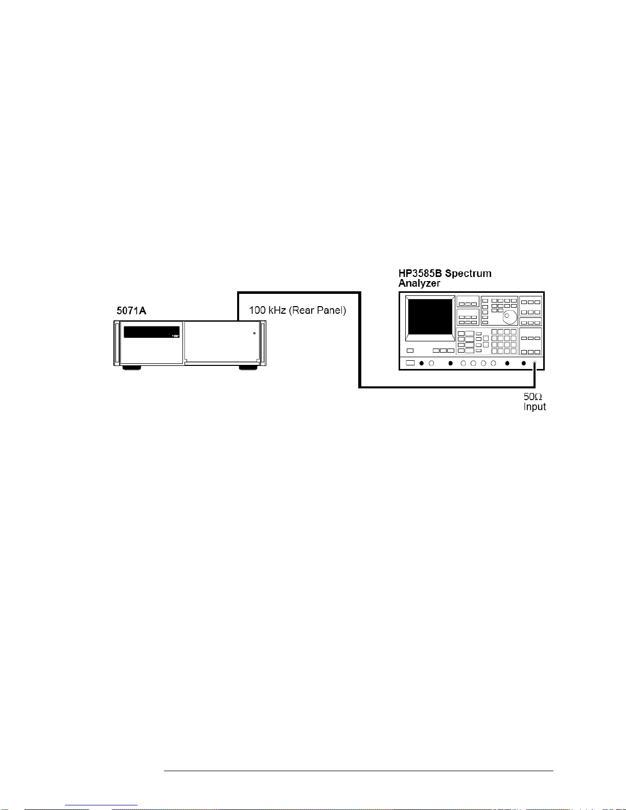
Test 1 — Output Signals: Harmonic Distortion
and Spurious Signals Check
A. Harmonic Distortion Check for the 5 and 10 MHz Outputs
Harmonics on the 10 MHz and 5 MHz output signals must be more than 40
dBc below the fundamental. To perform this check, a spectrum analyzer is
tuned to the fundamental frequency and an amplitude reference is
established. The output frequency spectrum is then examined to determine
fundamental-to-sideband amplitude relationship at harmonic points of the
fundamental.
Equipment
HP/Agilent 3585B Spectrum Analyzer
Setup
Figure 1-3. Harmonic Distortion Test Setup
Specifications
Verify all harmonics are < 40 dBc with respect to the fundamental
frequency.
10
Page 27

1. Performance Tests – Verifying Specifications
5071A Complete Performance Tests
Procedure
If you are using the HP/Agilent 3585B Spectrum Analyzer, follow the steps
below to test for harmonic signals on the 5 and 10 MHz outputs. If you are
using a different spectrum analyzer, use these steps as a guide for operation
of that analyzer.
1 Connect the 5071A Port 1 to the HP/Agilent 3585B analyzer as shown in
2 On the 5071A, set output ports 1 and 2 to 10 MHz using the front panel
3 On the HP/Agilent 3585B, perform the following steps:
Figure 1-3. Set the 3585B for 50 input impedance.
controls. See the section titled “Setting the Output Port Frequency” in the
5071A Operating and Programming Manual for instructions on how to do
this.
a) Press the green “INSTR PRESET” button and allow the analyzer
to go through its auto range algorithm (this takes about 5
seconds).
b) Press the “DISP LINE” (display line) button in the marker menu
and adjust the line to 40.0 dBc.
NOTE
c) Press the “PEAK SEARCH” button and then the “MKR->REF LVL”
button (both are in the marker menu area).
d) Set both the resolution bandwidth (RES BW) and the video
bandwidth (VIDEO BW) to 1 kHz. Enter the 1 kHz values using the
numeric and unit keys. The RES BW and VIDEO BW values are
displayed at the bottom of the screen.
The sweep time is 125 seconds. DO NOT adjust the sweep
time manually.
e) Press the “CONT” button in the sweep menu area to begin a new
sweep.
f) When the new sweep has passed through the fundamental
frequency, press the “PEAK SEARCH” button again. Then press
the “OFFSET” and the “ENTER OFFSET” buttons in the marker
menu area. Verify that both the offset frequency (Hz) and the
offset level (dB) go to zero (0 Hz and 0 dB should be displayed at
the top of the screen). If necessary, press and hold the “ENTER
OFFSET” button to zero-out the marker offsets.
g) When at least one sweep has completed, verify that there are no
harmonic signals on or above the 40dBc display line. Use the knob
in the marker area to move the offset marker to any harmonic signal
that you want to measure or record. The marker shows the offset
frequency and level in dBc from the output signal at 5 or 10 MHz.
Verify that there are no harmonically related signals on or above
40dBc within 5 harmonics of the fundamental.
11
Page 28

1. Performance Tests – Verifying Specifications
5071A Complete Performance Tests
4 On the 5071A, set output ports 1 and 2 to 5 MHz using the front
panel controls.
5 Repeat step 3.
6 Connect 5071A Port 2 to the HP/Agilent 3585B Spectrum
Analyzer and repeat steps 2 through 5 to test Port 2.
7 Record the actual reading in the appropriate place in the
Performance Test Record.
B. Non-Harmonic (Spurious) Signal Check for the 5 and 10 MHz Outputs
Non-harmonically related (spurious) signals on the 5 and 10 MHz outputs
must be more than 80 dBc below the output signal levels. To perform this
test, a spectrum analyzer is tuned to the 5 or 10 MHz signal and an amplitude
reference is established. The output frequency spectrum is then examined at
1 MHz on either side of the center frequency to determine the fundamentalto-sideband amplitude relationship for any signals occurring within this range.
Equipment
Setup
HP/Agilent 3585B Spectrum Analyzer
Figure 1-4. Non-Harmonic Distortion Test Setup
12
Page 29

1. Performance Tests – Verifying Specifications
5071A Complete Performance Tests
Specifications
All spurious nonharmonic signals must be < 80 dBc with respect to the
fundamental frequency.
Procedure
If you are using the HP/Agilent 3585B Spectrum Analyzer, follow the steps
below to test for spurious signals on the 5 and 10 MHz outputs. If you are
using a different spectrum analyzer, use these steps as a guide for operation
of that analyzer.
1 Connect the 5071A Port 1 to the 3585B analyzer as shown in
Figure 1-4. Set the 3585B for 50 input impedance.
2 On the 5071A, set output ports 1 and 2 to 10 MHz using the front
panel controls. See the section titled “Setting the Output Port
Frequency” in the 5071A Operating and Programming Manual for
instructions on how to do this.
3 On the 3585B, perform the following steps:
a) Press the green “INSTR PRESET” button and allow the analyzer
to go through its auto range algorithm (this will take about 5
seconds).
NOTE
b) Press the “DISP LINE” (display line) button in the marker menu
and adjust the line to 80.0 dBc.
c) Press the “PEAK SEARCH” button and then the “MKR->REF LVL”
button (both are in the marker menu area).
d) Set both the resolution bandwidth (RES BW) and the video
bandwidth (VIDEO BW) to 1 kHz. Enter the 1 kHz values using the
numeric and unit keys. The RES BW and VIDEO BW values are
displayed at the bottom of the screen.
The sweep time is 125 seconds. DO NOT adjust the sweep time
manually.
e) Press the “CONT” button in the sweep menu area to begin a new
sweep.
f) When the new sweep has passed through the fundamental
frequency, press the “PEAK SEARCH” button again. Then press
the “OFFSET” and the “ENTER OFFSET” buttons in the marker
menu area. Verify that both the offset frequency (Hz) and the
offset level (dB) go to zero (0 Hz and 0 dB should be displayed at
the top of the screen). If necessary, press and hold the “ENTER
OFFSET” button to zero-out the marker offsets.
13
Page 30

1. Performance Tests – Verifying Specifications
5071A Complete Performance Tests
g) When at least one sweep has completed, verify that there are no
spurious signals on or above the 80 dBc display line. Use the
knob in the marker area to move the offset marker to any spurious
signal that you want to measure or record. The marker shows the
offset frequency and level in dBc from the output signal at 5 or 10
MHz.
h) Verify that one of the following conditions is true:
No spurious signals are on or above the 80 dBc display line
between 4 MHz and 6 MHz for the 5 MHz output, or
No spurious signals are on or above the 80 dBc display line
between 9 MHz and 11 MHz for the 10 MHz output.
4 On the 5071A, set output ports 1 and 2 to 5 MHz using the front
panel controls.
5 Repeat step 3.
6 Connect 5071A Port 2 to the 3585B Spectrum Analyzer and
repeat steps 2 through 5 to test Port 2.
7 Record the actual reading in the appropriate place in the
Performance Test Record.
C. Harmonic Distortion Check for the 1 MHz Output
Harmonics on the 1 MHz output signal must be more than 40 dBc below the
fundamental. To perform this check, a spectrum analyzer is tuned to the
fundamental frequency and an amplitude reference is established. The output
frequency spectrum is then examined to determine the fundamental-tosideband amplitude relationship at harmonic points of the fundamental.
Equipment
HP/Agilent 3585B Spectrum Analyzer
Setup
Figure 1-5. 1MHz Output Harmonic Distortion Test Setup
14
Page 31

1. Performance Tests – Verifying Specifications
5071A Complete Performance Tests
Specifications
All harmonics must be < 40 dBc with respect to the fundamental frequency.
Procedure
If you are using the HP/Agilent 3585B Spectrum Analyzer, follow the steps
below to test for harmonic signals on the 1 MHz output. If you are using a
different spectrum analyzer, use these steps as a guide for operation of that
analyzer.
1. Connect the 5071A 1 MHz output to the 3585B Spectrum Analyzer as shown
in Figure 1-5. Set the 3585B for 50 input impedance.
2. On the 3585B, perform the following steps:
a. Press the green “INSTR PRESET” button and allow the analyzerto go
through its auto range algorithm (this will take about 5 seconds).
b. Press the “STOP FREQ” button. Then set the stop frequency to 20 MHz
using the numeric and unit keys in the entry menu.
c. Press the “DSP LINE” button and move the display line to40.0 dBc.
d. Press the “PEAK SEARCH” button, then the “MKR->REF LVL” button.
e. When the new sweep has passed through the fundamental frequency,
press the “OFFSET” and the “ENTER OFFSET” buttons in the marker
menu area. Verify that both the offsetfrequency (Hz) and the offset level
(dB) go to zero (0 Hz and 0 dBshould be displayed at the top of the
screen). If necessary, pressand hold the “ENTER OFFSET” button to
zero-out the markeroffsets.
f. When at least one sweep has completed, verify that there are no
signals on or above the 40 dBc display line at multiples of 1 MHz up to
4 MHz. Use the knob in the marker area to move the offsetmarker to
any signals within this range if you want to measure or record these
signals. The marker shows the offset frequency and level in dBc from
the 1 MHz signal.
3. Record the actual reading in the appropriate place in the Performance Test
Record.
15
Page 32
1. Performance Tests – Verifying Specifications
5071A Complete Performance Tests
D. Harmonic Distortion Check for the 100 kHz Output
Harmonics on the 100 kHz output signal must be more than 40 dBc below the
fundamental. To perform this check, a spectrum analyzer is tuned to the
fundamental frequency and an amplitude reference is established. The output
frequency spectrum is then examined to determine fundamental-to-sideband
amplitude relationship at harmonic points of the fundamental.
Equipment
HP/Agilent 3585B Spectrum Analyzer
Setup
Figure 1-6. 100 kHz Harmonic Distortion Test Setup
Specifications
All harmonics must be < 40 dBc with respect to the fundamental frequency.
Procedure
If you are using the HP/Agilent 3585B Spectrum Analyzer, follow the steps
below to test for harmonic signals on the 100 kHz output. If you are using a
different spectrum analyzer, use these steps as a guide for operation of that
analyzer.
1 Connect the 5071A 100 kHz output to the 3585B Spectrum Analyzer as
shown in Figure 1-6. Set the 3585B for 50 input impedance.
2 On the 3585B, perform the following steps:
a. Press the green “INSTR PRESET” button and allow the analyzer to go
through its auto range algorithm (this will take about 5 seconds).
b. Press the “STOP FREQ” button. Then set the stop frequency to 3 MHz
using the numeric and unit keys in the entry menu.
c. Press the “DSP LINE” button and move the display line to 40.0 dBc.
16
Page 33

1. Performance Tests – Verifying Specifications
5071A Complete Performance Tests
d. Press the “PEAK SEARCH” button, then the “MKR->REF LVL” button.
e. Set the resolution bandwidth (RES BW) to 300 Hz and the video
bandwidth (VIDEO BW) to 1 kHz.
NOTE The sweep time is 66.8 seconds. DO NOT adjust the sweep
time manually.
f. Press the “CONT” button in the sweep menu area to begin a new
sweep.
g. When the new sweep has passed through the fundamental frequency,
press the “OFFSET” and the “ENTER OFFSET” buttons in the marker
menu area. Verify that both the offset frequency (Hz) and the offset
level (dB) go to zero (0 Hz and 0 dB should be displayed at the top of
the screen). If necessary, press and hold the “ENTER OFFSET” button
to zero-out the marker offsets.
h. When at least one sweep has completed, look for any signals that
appear on or above the 40 dBc display line at multiples of 100 kHz up
to 500 kHz. Use the knob in the marker area to move the offset marker
to any signals within this range if you want to measure or record these
signals. The marker shows the offset frequency and level in dBc from
the 100 kHz signal.
3 Record the actual reading in the appropriate place in the Performance Test
Record.
17
Page 34

1. Performance Tests – Verifying Specifications
5071A Complete Performance Tests
Test 2 — Frequency Accuracy
The following accuracy check measures the changing phase relationship
between the 5071A 10 MHz output and another primary frequency standard
(5071A Primary Frequency Standard or better). An HP/Agilent K34-59991A
Linear Phase Comparator is used to measure the phase between the 5071A
under test and the reference standard.
NOTE
In this test, the reference standard must be of known accuracy. The
measurement time must be of sufficient length so the accuracy of
the measurement is not impaired by the stability of either the
reference standard or the unit under test. If the reference standard is
a 5071A with the High-Performance CBT, the accuracy
measurement must be made for 24 hours if the unit under test is a
Long-Life (Standard) CBT. The test can be made in 2 1/2 hours if
the unit under test has the High-Performance CBT.
Equipment
HP/Agilent K34-59991A Linear Phase Comparator
Strip Chart Recorder
Setup
Figure 1-7. Frequency Accuracy Test Setup
18
Page 35

1. Performance Tests – Verifying Specifications
o
5071A Complete Performance Tests
Specifications
NOTE
Long-Life (Standard): 1x10
High-Performance: 2x10
The accuracy of the 5071A is better than 2x10
1x10
known with sufficient precision to make this measurement accurately.
Procedure
1 The 5071A must be on for at least 30 minutes and the green
2 Connect the HP/Agilent K34-59991A Phase Comparator OUTPUT
3 Turn on the K34-59991A power.
4 Connect the 10 MHz reference to INPUT A and the 5071A (unit
5 Set K34-59991A “ZERO-OPER-FULL” front panel mounted toggle
12
13
-13
-12
(Long-Life). Be sure the accuracy of the reference standard is
(High-Performance)
continuous operation LED must be on.
terminals to the strip chart recorder as shown in Figure 1-7. Set
the recorder for 1V full scale and 1 inch/hour. Turn on the
recorder.
under test) 10 MHz to INPUT B as shown in Figure 1-7.
switch to “ZERO.” Adjust the “ZERO SCALE” control for a zero
reading on the meter. Then adjust the recorder for a zero
indication.
6 Set K34-59991A switch to “FULL” and adjust “FULL SCALE”
control for a full scale reading on the recorder.
7 Check both “ZERO” and “FULL SCALE” settings on the recorder
and readjust if necessary.
8 Set K34-59991A switch to “OPER” for normal operation.
9 The recorder now provides a continuous record of the phase
difference between the reference standard and the 5071A unit
under test. When its output reaches full scale (360 degrees), the
K34-59991A will automatically reset to 0 (0 degrees).
10 With the recorder set as described, the phase record is 100 ns full
scale (with 10 MHz inputs). The figure below shows an example of
a frequency difference measurement under these conditions.
11 The frequency difference between the unit under test and the
reference is given by the following equation:
f/F = t/T
Where: f/F is the desired frequency difference, and t is the
phase change (in seconds) over the measurement time, T.
The Figure 1-8 shows a typical plot using the strip chart recorder.
19
Page 36

1. Performance Tests – Verifying Specifications
5071A Complete Performance Tests
NOTE
Figure 1-8. Error Measurement
In the example, the frequency difference, f/F, is computed as follows:
f/F = t/T
t
= (7 minor divisions × 2x10
= 14x10
T
= 8 hours or 2.88 × 10
f/F
= t/T = 14 × 10
= 4.9 × 10
-13
9
seconds
-9
/2.88 × 10
or 4.9 parts in 1013
-9
seconds/minor divisions)
4
seconds
4
This shows that frequency difference between the unit under test and the
reference is 4.9 parts in ten to the 13th. This is only an example. The
measured frequency accuracy of a 5071A should be 1 x 10
13
Long-Life (Standard), or 2 x 10
or better for a high performance unit
12
or better for a
The final computation should include the accuracy of the reference
source.
12 Record the actual reading in the appropriate place in the
Performance Test Record.
20
Page 37

1. Performance Tests – Verifying Specifications
5071A Complete Performance Tests
Test 3 — Stability
NOTE
High accuracy precision measurements of time stability are
available through the National Institute of Standards and
Technology (NIST) in the USA. NIST can completely characterize
and verify all major specifications of the 5071A. For information
regarding the various tests available, contact:
M.C. 847.4
National Institute of Standards and Technology
325 Broadway
Boulder CO 80303-3328
USA
Telephone: (303) 497-3753
A. Time Domain
This is an engineering-level measurement requiring a special test setup. The
test setup must be carefully designed to eliminate all sources of noise. For
more information on how to make this measurement, see NIST Technical
Note 1337 (available from US Government Printing Office, Washington DC.,
USA). This is an excellent theoretical as well as technical reference for this
measurement.
Record the actual reading in the appropriate place in the Performance Test
Record. This completes the performance test.
B. Frequency Domain
This measurement requires the HP/Agilent 3048A or equivalent Phase Noise
Measurement System, a highly specialized test system. In order to perform
properly, this system must contain a reference oscillator with phase noise
characteristics that are equal to or better than the 5071A. Instructions for
performing frequency domain stability tests can be found in the HP/Agilent
3048A system documentation.
Record the actual reading in the appropriate place in the Performance Test
Record.
21
Page 38

1. Performance Tests – Verifying Specifications
5071A Complete Performance Tests
Performance Test Record
Model 5071A Primary Frequency Standard
Serial Number:
Test Performed By: Temperature:
Date: Relative Humidity:
Notes:
Repair/Work Order No.
Test
Number Operational Verification
1
2
3
Test
Number Description
1
Power-On Self-Tests/Servo Lock
Rear-Panel Output Signal Checks
RS-232 Serial Port Verification
Complete Performance Tests
Output Signals: Harmonic Distortion
and Spurious Signals Check
A. Harmonic Distortion Check for
the 5 and 10 MHz Outputs
B. Non-harmonic (Spurious)
Signal Check for the 5 and
10 MHz Outputs
C. Harmonic Distortion Check for
the 1 MHz Output
D. Harmonic Distortion Check for
the 100 kHz Output
Pass Fail
_______ ______
_______ _______
_______ _______
Actual
Reading
____________
____________
____________
____________
Test Results
Limits
Greater than 40 dBc
Greater than 80 dBc
Greater than 40 dBc
Greater than 40 dBc
22
Page 39

1. Performance Tests – Verifying Specifications
5071A Complete Performance Tests
Number
Test
2
3
Description
Frequency Accuracy
Stability
A. Time Domain
B. Frequency Domain
Actual
Reading
____________
____________
____________
Limits
Long-Life:
12
-
1x10
High-Performance:
13
-
2x10
See Specifications
table in Chapter 6 of
this manual.
23
Page 40

1. Performance Tests – Verifying Specifications
5071A Complete Performance Tests
24
Page 41

2. Service
Introduction
NOTE
In the interest of PRESERVING its usability most of the
information in this chapter has been retained in its original form.
No attempt has been made to update the equipment, accessories,
or parts to reflect current availability. It is therefore necessary for
the user of this manual to consider the recommendations of test
equipment and accessories as suggestions. Some or all of these
items may no longer be available from Symmetricom or any other
vendors. An updated list of available replacement parts from
Symmetricom is provided in Chapter 5.
This chapter provides service information for your 5071A and is divided into
three major sections:
Returning the Instrument to Symmetricom for Service. This section
provides you with step-by-step instructions on how to return the
instrument for service.
Pre-Troubleshooting Information. This section provides you with pertinent
information such as safety considerations, recommended test equipment,
repair and after service considerations, service accessories, and
assembly identification and location.
Diagnostic Trees and Procedures. This section provides you with
diagnostic trees and procedures to isolate faulty assemblies or modules.
(Once you find a faulty assembly or module, use Chapter 4, “Replacing
Assemblies,” to remove the defective assembly and replace it with a
functioning unit.)
If the instrument is under warranty, return the instrument to Symmetricom for
service. Refer to the first section of this chapter titled “Returning the
Instrument to Symmetricom.” If you decide to troubleshoot the instrument
yourself, refer to the section titled “Diagnostic Trees and Procedures.”
25
Page 42

2. Service
Returning the Instrument to Symmetricom for Service
Returning the Instrument to
Symmetricom for Service
To Provide Repair Information
If you are shipping the instrument to Symmetricom for service or repair, call
your nearest Symmetricom sales representative or distributor to make
arrangements. Alternatively you can visit our web site at
http://www.symmetricom.com/support/warrantyandrepair and fill out the form
to receive an RMA and return address information.
IMPORTANT
NOTE
If you do not have the original shipping container for the 5071A it is
STRONGLY recommended that you first order the packaging kit part
number 59991-91105 from Symmetricom before returning for repair.
This kit provides all the necessary packaging material to give the
greatest amount of protection against shipping damage. Any 5071A
received for repair in any other packaging and found damaged will
not be covered under any Symmetricom warranty program. Such
damage will be evaluated and you will be provided with a quotation to
repair such damage before regular repair or calibration can be
performed.
It is also advised that all hazardous materials regulations for labeling be
followed for your local and country laws. The following web site will provide
you with up-to-date instructions: http://www.symmttm.com/5071A/Shipping/
Be sure to include the RMA with the shipment.
To Pack in the Original Packaging Materials
To protect your 5071A against shipping damage repack the instrument in its
original packaging for shipment. Shipping kit Part Number 59991-91105 is
available through Symmetricom. In any correspondence, refer to the instrument
by the model number and complete serial number.
1 Disconnect the power cord, probes, cables, or other accessories
attached to the instrument.
2 Make sure the folded corrugated spacer (which normally contains
the manuals) is in the box to ensure proper fitting.
3 Make sure the four polystyrene corner blocks are in their proper
positions in the box.
4 Place the instrument on the four polystyrene corner blocks with
the 3-ply pad at the rear panel end of the instrument.
26
Page 43

2. Service
Pre-Troubleshooting Information
5 Place four more polystyrene corner blocks on top of the
instrument to secure it.
6 Do not return the manuals with the instrument. Return an
accessory only when it is a part of the failure symptoms.
7 Seal the shipping container securely.
8 Apply the appropriate shipping labels.
Pre-Troubleshooting Information
This section contains the following pertinent troubleshooting information:
Safety Considerations
Recommended Test Equipment
Repair Considerations
After Service Considerations
Service Accessories
Assembly Identification and Location
WARNING
Safety Considerations
Although this instrument has been designed in accordance with international
safety standards, this manual contains information, cautions, and warnings
which must be followed to ensure safe operation and to retain the instrument
in a safe condition. Service instructions, and adjustment procedures requiring
removal of the instrument cover, are for use by service-trained personnel
only. To avoid dangerous electric shock, do not perform any servicing or
make any adjustments with the cover removed, unless qualified to do so.
BEFORE APPLYING AC POWER, THE INSTRUMENT AND ALL
PROTECTIVE EARTH TERMINALS, EXTENSION CORDS, AUTO
TRANSFORMERS, AND DEVICES CONNECTED TO THE
INSTRUMENT SHOULD BE CONNECTED TO A PROTECTIVE
EARTH GROUNDED SOCKET.
ANY INTERRUPTION OF THE PROTECTIVE GROUNDING
CONDUCTOR INSIDE OR OUTSIDE THE INSTRUMENT OR
DISCONNECTION OF THE PROTECTIVE EARTH TERMINAL
WILL CAUSE A POTENTIAL SHOCK HAZARD THAT COULD
RESULT IN PERSONAL INJURY. INTENTIONAL
INTERRUPTION IS PROHIBITED.
Any adjustment, maintenance, and repair of the opened instrument under
voltage should be avoided as much as possible and, if necessary, should be
carried out only by a skilled person who is aware of the hazards involved (for
example, fire and electric shock).
27
Page 44

2. Service
Pre-Troubleshooting Information
Recommended Test Equipment
Test equipment recommended for testing and troubleshooting the
5071A is listed in Chapter 1, “Performance Tests.” Substitute equipment
may be used if it meets or exceeds the required characteristics listed in Table
1-1.
Repair Considerations
Electrostatic Discharge
Electronic components and assemblies in the 5071A can be permanently
degraded or damaged by electrostatic discharge. Use the following
precautions when servicing the instrument:
1 ENSURE that static sensitive devices or assemblies are serviced
at static safe workstations providing proper grounding for service
personnel.
2 ENSURE that static sensitive devices or assemblies are stored in
static shielding bags or containers.
3 DO NOT wear clothing subject to static charge buildup, such as
wool or synthetic materials.
4 DO NOT handle components or assemblies in carpeted areas.
5 DO NOT remove an assembly or component from its static
shielding protection until you are ready to install it.
6 AVOID touching component leads. (Handle by packaging only.)
Disassembly and Reassembly Specifics
Refer to the Chapter 4, “Replacing Assemblies,” in this manual for complete
disassembly and reassemble details, and Chapter 5, “Replaceable Parts” for
an exploded view of the instrument parts.
After Service Considerations
Product Safety Checks
The following safety checks must be performed after any trouble-shooting
and repair procedures have been completed to ensure the safe operation of
the instrument.
WARNING
RESISTANCE CHECKS DESCRIBED IN THE FOLLOWING TEXT
REQUIRE THAT THE POWER CORD BE CONNECTED TO THE
INSTRUMENT AND THAT AC POWER BE DISCONNECTED. BE
SURE THAT THE POWER CORD IS NOT CONNECTED TO
POWER BEFORE PERFORMING ANY SAFETY CHECKS.
28
Page 45

2. Service
Pre-Troubleshooting Information
1 VISUAL INSPECTION. Visually inspect the interior of the
instrument for any signs of abnormal internally generated heat,
such as discolored printed circuit boards or components,
damaged insulation, or evidence of arcing. Determine and remedy
the cause of any such condition.
2 GROUND CONTINUITY TEST. Plug the power cord into the rear-
panel power receptacle. (DO NOT connect the instrument to ac
power at this time.) Using a suitable ohmmeter, check resistance
from the instrument's metallic connection (such as the rear panel
or BNC ground collar) to the ground pin on the power cord plug.
The reading must be less than 1. Flex the power cord while
making this measurement to determine whether intermittent
discontinuities exist.
3 Check any indicated front or rear panel ground terminals marked,
using the above procedure.
4 INSULATION RESISTANCE TEST. Tie the line and neutral pins of
the power cord plug together. Measure the resistance from the
instrument enclosure (chassis) to the line and neutral pins of the
power cord plug. The minimum acceptable resistance is 2 M.
Replace any component that results in a failure.
5 LINE FILTER/CABLE ASSEMBLY CHECK. Check the line fuse
and voltage selector card in the rear panel line filter/cable
assembly to verify that the instrument is properly set for the ac-
power source to be applied.
Product Performance Checks
After replacement of any assembly or module, perform the Operational
Verification Test in Chapter 1, “Performance Test,” of this manual.
Service Accessories
Service accessories for troubleshooting the 5071A are available from
Symmetricom. Table 2-1 lists the items in the 5071A Service Accessories Kit.
The list includes the name, the part number, and a brief description and use
of each item.
29
Page 46

2. Service
Pre-Troubleshooting Information
Table 2-1. Service Accessories Kit (05071-67003) Contents
Accessory Part Number Use
Service Manual 05071-90040 Corrective maintenance
Extender board for short PCAs 05071-60051 A4, 6, 7, 8 diagnosis
Extender board for long PCAs 05071-60052 A2,3 diagnosis
100 nA Current Source (powered by A6) 05071-60274 A14 diagnosis
SO-8 SMT Dip clip (#5250 ITT Pomona) 1400-1708 SMT signal access
SO-14 SMT Dip clip (#5251) 1400-1705 SMT signal access
SO-16 SMT Dip clip (#5252) 1400-1706 SMT signal access
SO-20 SMT Dip clip (#5253) 1400-1707 SMT signal access
30
Page 47

2. Service
Pre-Troubleshooting Information
Assembly Identification and Location
The assembly number, name and part number of the 5071A assemblies are
listed in Table 2-2. Figures 2-1 and 5-2, illustrate the replaceable assemblies
and cables in the 5071A.
Table 2-2. 5071A Assembly Identification
Assembly Name Part No.
A1
A1
A2 CBT Controller Assembly 05071-60202
A3 Microprocessor Assembly 05071-68003
A4 Digital Synthesizer Assembly 05071-68004
A5 87 MHz PLL Module 05071-60272
A6 Servo Assembly 05071-68006
A7 Interface Assembly 05071-68007
A8 1 PPS Assembly 05071-68008
A9 Frequency Multiplier Module 05071-60292
A10 Output Frequency Distribution Amplifier Module 05071-60210
A11
A11
A12
A12
A13 Front-Panel PC Assembly 05071-60213
A14 Signal Amplifier Module 05071-60214
Motherboard Assembly
Motherboard Assembly, Opt.048 only
Power Steering Logic Assembly, Std
Power Steering Logic Assembly, Opt. 048 only
Dc-Dc Power Converter Module
DC-DC Power Converter Module. Opt. 048 only
05071-68001
05071-68028
05071-68029
05071-68033
05071-60212
05071-60279
A15 9.2 GHz Microwave Generator Module 05071-60215
A16 High Voltage Supply Module 05071-60216
A17 CBT (Cesium Beam Tube) Assembly
A18 9.2 GHz PLL Module 05071-60218
A19 Reference Oscillator (Quartz) Module 05071-60294
LF1 Line Filter/Cable Assembly 05071-60259
T1
T1
31
or
Option 001 High Performance CBT Assembly
Toroidal Power Transformer
Toroidal Power Transformer, Opt. 048 only
10890A
10891A
9100-4962
9100-5134
Page 48

2. Service
Pre-Troubleshooting Information
Figure 2-1. Instrument Top View
32
Page 49

2. Service
Diagnostic Trees and Procedures
The following sections contain diagnostic-troubleshooting trees (diagnostic
trees) in the form of stepwise procedures and Yes/No decision points. The
intent of this process is to isolate a faulty printed circuit assembly (PCA) or
module. Component-level troubleshooting is NOT supported in this manual,
except for the A1 motherboard.
Troubleshooting on the 5071A requires disassembly for access. Refer to the
“Disassembly and Reassembly” procedures in chapter 4 for that information.
Assembly specific tests and probing frequently requires the use of either a
long or short PCA extender board. The extender boards and their part
numbers are listed in Table 2-1.
NOTE
NOTE
Following the diagnostic-tree procedures is essential to
isolating the faulty assembly or module. If the internal self
test diagnostics are used without reference to this process,
misleading results may be obtained, leading to improper and
unproductive repair actions. Besides the diagnostics, other
means are required to localize and isolate the problem PCA
or module. These include visual checks of LEDs, and LCD
display messages along with test equipment checks such as
scope, multimeter, or spectrum analyzer tests.
The diagnostic self tests may be executed via SCPI commands, or from the
5071A front-panel software interface. All the information is given in the
description of the diagnostic trees.
Ensure that all internal modules and assemblies are correctly
installed and all interconnect cables are present and properly
routed. (Refer to the functional-block interconnect tables in
chapter 3, “Theory of Operation” for cable interconnect
information.) Each PCA must be fully seated in its correct
bus slot position on the A1 motherboard. (A9J101 if present
is capped with no connection.)
33
Page 50

2. Service
Diagnostic Trees and Procedures
5071A Diagnostic Tree Organization
Diagnostic-Tree Section 1 - Top-level Diagnostics Trees:
provides the beginning entry point for the troubleshooting process;
organized around start-up events, front-panel operation/messages, and
rear-panel output/input signals.
Diagnostic-Tree Section 2 - Functional-Group Diagnostic Trees:
provides diagnostic trees for any two or more assemblies or modules that
interact with each other in the normal performance of instrument
operation.
Diagnostic-Tree Section 3 - Assembly/Module Diagnostic Trees:
provides diagnostic trees for individual assemblies and modules when
indicated by either Top-level tree pointers or Functional-Group tree
pointers.
Navigating the Diagnostic Trouble-Tree
Sections
1 Go to the beginning of the Top-level diagnostic tree:
a) If you already know the symptom/operating problem - go to the
subsection in section 1 that provides its fault isolation.
b) If you do not know what's wrong with a failed instrument, start at
the beginning of the Top-level tree checking all items sequentially
until you find a specific isolated fault or find a pointer to further
details in sections 2 or 3.
2 If you know for certain
exists, go to the applicable Functional-Group diagnostic tree in
section 2. (If replacement of an obviously defective component
does not restore normal operation, then you must start at step 1b
above).
3 If you know for certain
fault, go to section 3, Assembly/Module diagnostic trees to locate
the applicable diagnostic tree. (If replacement of an obviously
defective component does not restore normal operation, then you
must start at step 1b above.)
the general hardware area where the fault
that a particular assembly/module is at
34
Page 51

2. Service
Diagnostic Trees and Procedures
Top-Level Diagnostic Tree Organization
The following list of titles outlines the organization of the Top-Level
Diagnostic tree and its seven subsections:
Top-Level Diagnostic Tree (Diagnostic Section 1)
1.0.0 First Power On
1.0.1.1 Digital Supply Voltage Check
1.0.1.2 A3 Microprocessor Fault
1.0.2 Dc-Supply Test/Log-Record Examination
1.0.3 Power On Fatal Error Check
1.0.4 Instrument Self Tests
1.0.5 CBT Warm Up
1.0.6 Servo-Lock Warning State
1.0.7 User-Input/Output Checks
1.0.8 5071A Profiling
1.0.8.1 Profiling Results Interpretation
1.0.8.2 Conclusion of Diagnostic Procedure
1.0.9 Delayed Failures, Warnings, and Messages
1.0.9.1 Delayed Fatal Errors
1.0.9.2 Delayed Warnings
1.0.9.3 Delayed Advisory Messages
Power-On Fatal-Error Diagnostic Tree (Diagnostic Subsection 1)
1.1.1 Fatal Error Interpretation
1.1.2 Sequencer Error Test
1.1.2.1 1 PPS Assembly 80 MHz Input Test
1.1.3 Tube PROM Test
Self Test Diagnostic Tree (Diagnostic Subsection 2)
1.2.1 Self Test Failure Interpretation
1.2.2 Pps Interrupt Error Test
35
Page 52

2. Service
Diagnostic Trees and Procedures
Warm-up and Operating Fatal Error Diagnostic Tree
(Diagnostic Subsection 3)
1.3.1 Warm-Up/Operating Error
1.3.1.1 Operating Error-Code Interpretation
1.3.2 Interpreting Warm-Up Errors
1.3.2.1 Cs Oven Failed: Ion-Pump Over current Warm-up Error
1.3.2.2 A16/CBT Excess Ion-Pump Current Test
1.3.3 CBT Signal Fatal Errors
1.3.4 CBT Shutdown Message
1.3.5 Cs Oven Timeout Test
1.3.6 CBT Background Signal Warm-Up Errors
1.3.7 CBT Depth of Modulation Warm-Up Errors
1.3.7.1 CBT Support Circuits Test
1.3.8 RF Level Control-Current Test
Warning Message Diagnostic Tree (Diagnostic Subsection 4)
1.4.1 Warning Message Interpretation
1.4.2 Signal Gain at Range Limit/CBT Signal Low
1.4.3 5071A Profiling (CBT Performance Evaluation)
1.4.4 Power Source is Batt (Ignore this for Opt 048)
1.4.4.1 Ac Line Operation - Battery Indicator On
1.4.4.2 Instrument Ac Power Absent
1.4.4.2.1 A1C4 Voltage Test
1.4.4.3 LF1/T1 Transformer Fault Verification
I/O Diagnostic Tree (Diagnostic Subsection 5)
1.5.1 Input/Output Faults
CBT Performance Evaluation (Diagnostic Subsection 6)
1.6.0 Running the 5071A Profiling Software
1.6.1 5071A Profiling Results Evaluation
Advisory Messages (Diagnostic Subsection 7)
1.7.1 Advisory Message Interpretation
36
Page 53

2. Service
Top-Level Diagnostic Tree (Diagnostic Section 1)
Top-Level Diagnostic Tree
(Diagnostic Section 1)
This section describes the top-level diagnostic procedures for the 5071A
Primary Frequency Standard and provides pointers to lower-level procedures.
It is complete and must be performed sequentially. The procedures are
designed to troubleshoot an instrument that has failed in normal operation,
and is no longer able to lock-up correctly at power on.
When the complete procedure is performed on a functional 5071A, it will end
at section 1.0.8.2 with no errors or failures. The operational verification and
Performance Test procedures described in Chapter 1 of this manual must be
performed successfully on a repaired instrument before it is placed back in
service.
A transient error condition is evident when an instrument generates an error
or warning but subsequently passes the operational verification procedure
without any repair. This could for example occur when the cesium beam tube
(CBT) nears the end of its life.
In case of difficulty, contact Symmetricom for assistance.
1.0.0 First Power On
1 Remove the instrument from service.
2 Remove all external power.
3 Disconnect the internal-standby battery. (See Operating and Programming
manual, pg 2-15). (For Opt. 048, ensure that the rear-panel dc-line fuse
holder has a good fuse of the correct rating).
4 Ensure that rear-panel ac-line filter/cable assembly has a good fuse.
5 Remove 5071A top/bottom covers and top inner shield (see pg 4-3).
6 Power on the 5071A by applying dc or ac power.
7 Verify that all front-panel LEDs, the LCD, beeper, and keypad work:
a. Observe the large red seven-segment and small amber LEDs
momentarily illuminate.
b. Observe the LCD illuminate its top row of pixels followed by normal two-
row-display operation.
c. Check each key by pressing it and either hear or observe a confirming
response.
NOTE a & b above should occur within first few seconds of
operation.
QUESTION: Is the front-panel functional (beeper, LEDs, keyboard
operational)?
37
Page 54

2. Service
Top-Level Diagnostic Tree (Diagnostic Section 1)
If Yes: Go to, 1.0.2.
If No: Disconnect power immediately and check the appropriate rear panel
power fuse.
If fuse is intact, Go to, 1.0.1.1. (For Opt. 048 Go to 1.0.1.1.0.)
If fuse is blown, Go to, 2.1.1.1.0 (Power supply diagnostic tree).
1.0.1.1.0 DC Input 1 and 2 Power Steering
Circuit Check
1 Use the DC Input 1 and 2 Power Steering Schematic (Figure 2-1.)
located on page 32 of this chapter to troubleshoot the dc power
input steering function.
QUESTION: Is the DC input power steering circuit functional?
If Yes: Go to, 1.0.1.1.
If No: Replace the 48V Sub-panel Assembly (P/N 05071-60277) and retest.
1.0.1.1 Digital Supply Voltage Check
1 Install the short extender board (part number 05071-60051) into
the spare slot on the A1 motherboard.
2 Use a DMM with a point-tipped probe to verify +5V supply on the
extender board test points.
QUESTION: Is +5V between 5.28 to 5.50 volts?
If Yes: Go to, 1.0.1.2
If No: Go to, 2.1.1.1.0 (Power-Supply diagnostic tree).
1.0.1.2 A3 Microprocessor Fault
1 Observe upper edge row of LEDs on A3 microprocessor
assembly.
QUESTION: Are LED DS6 lit and LEDs DS1 - DS4 extinguished?
If Yes: Remove power, replace A13 (see page 159.), and retest.
If No: Remove power, replace A3, and retest.
38
Page 55

2. Service
Top-Level Diagnostic Tree (Diagnostic Section 1)
1.0.2 DC-Supply Test/Log-Record Examination
1 If the INFO/STATUS menu selections display Warming
up, use
the CONFIG, MODE, and STANDBY menu selections to place the
5071A into STANDBY mode. (This will put the instrument into a
stable state if it has not gone to Fatal Error mode.)
2 Record all information in the log (LOG/BROWSE menu selections).
3 Clear the log (use LOG/CLEAR).
4 Install the short extender board (part number 05071-68051) into
the spare slot on the A1 motherboard.
5 Use a DMM (with point-tipped probes) set for dc volts to measure
the +5, +12, and -12 volt supplies on the extender-board test-
voltage points to chassis ground. They should all be within the
following ranges:
+5V = 5.28 to 5.50 volts
+12V = 12.08 to 12.40 volts
-12V = -12.08 to -12.40 volts
QUESTION: Are the measured voltages within the given ranges?
If Yes: Go to, 1.0.3
If No: Go to, 2.1.1.1.0 (Power-supply diagnostic tree).
39
Page 56

2. Service
Top-Level Diagnostic Tree (Diagnostic Section 1)
1.0.3 Power On Fatal Error Check
1 Cycle power to the instrument, wait fifteen seconds.
2 Go to the INFO/STATUS section of the front-panel menu.
QUESTION: What state is the 5071A in?
If Warming Up, Go to, 1.0.2, perform step 1, then go to 1.0.4.,
NOTE
If in Fatal
For some test purposes it is useful to force the instrument into the
fatal error state. This can be done by applying power with A2P3
disconnected from A2J2.
Error, Go to, 1.1.1 (Power-On Fatal-Error diagnostic tree).
1.0.4 Instrument Self Tests
1 Execute all Self tests from front panel in Standby mode as follows:
a) Go to the UTIL menu, select TEST option, and press Enter.
b) Press INC to initiate the Self test cycle.
c) Observe the front-panel display CYCLES = 0: when 0 changes to
1 or greater, all Self tests have passed.
d) If a Self test routine fails, record the displayed message and attempt
to continue the tests by pressing INC again.
e) Press DEC to halt Self test execution.
QUESTION: Did the 5071A pass all the Self tests?
If Yes: Go to, 1.0.5
If No: Go to, 1.2.1 (Self-test diagnostic tree).
1.0.5 CBT Warm Up
1 Change operating mode to NORMAL (press CONFIG, MODE, and
NORMAL), the instrument state changes to Warming up.
2 Wait until the green LED is flashing, or 45 minutes have passed.
QUESTION: Does the green LED continue to flash for at least
If Yes: Go to, 1.0.6.
If No: Go to, 1.3.1, Warm-up and Operating Error diagnostic tree.
40
60 seconds?
(For delayed error conditions, go to 1.0.9.)
Page 57

2. Service
Top-Level Diagnostic Tree (Diagnostic Section 1)
1.0.6 Servo-Lock Warning State
QUESTION: Is the amber LED flashing?
If Yes: Go to, 1.4.1, Warning-Message diagnostic tree. (For delayed
error/warnings go to 1.0.9.)
If No: Go to, 1.0.7.
1.0.7 User-Input/Output Checks
1 Check the performance of the following outputs/inputs:
(Refer to chapter 1, page 1-8 to verify operation and page 1-7 in
the Operating and Programming manual for checking the Sync
inputs with a pulse source.)
a) Both 5/10MHz outputs,
b) 1 MHz output,
c) 100 kHz output,
d) RS232 port,
e) All 1PPS outputs,
f) Both Sync inputs
g) Status Output
1) Use an oscilloscope to verify TTL-high state.
2) Put the instrument into Standby.
3) Verify transition to TTL-low state.
4) Return the instrument to Normal.
QUESTION: Did all Input/Output checks pass?
If Yes: Go to, 1.0.8.
If No: Go to, 1.5.1 (I/O diagnostic tree).
41
Page 58

2. Service
Top-Level Diagnostic Tree (Diagnostic Section 1)
1.0.8 5071A Profiling
Successful completion of the preceding tests indicate that all functional
blocks of the 5071A under test are operational. This is confirmed by the
instruments' ability to lock-up its servo loops successfully with no errors.
These tests are however, not sufficiently detailed to predict the accuracy or
stability of the instrument, which could be degraded by noise or instability in
the CBT and the electronic circuits.
Because the operating accuracy and stability of the 5071A can only be
confirmed by long observations, it is useful to assess the noise contribution of
the CBT at the completion of the top-level test procedure. The CBT has a
finite lifetime, and measurements of its operating parameters may be used to
give advanced warning of required service.
1 Perform the 5071A profiling procedure provided at 1.6.0. The procedure has
no effect on the timekeeping performance of the instrument, and may be
conducted on an 5071A currently in use. The procedure requires only that the
instrument will run in Normal Operation mode.
2 When the profiling software has generated its report, use the following
information to evaluate the results.
1.0.8.1 Profiling Results Interpretation
Signal to Noise Ratio
The Signal to Noise Ratio is an estimate of the current overall operating
condition of both the CBT and instrument electronics.
If the result is Band 1, the instrument's stability should meet specification.
CBT problem is unlikely.
If the result is Band 2, the test is indeterminate. High Probability that
CBT is performing to specifications.
If the result is Band 3, instrument stability will probably not meet
specification. CBT problem is likely. Consult Chapter 1 on Performance
Tests to confirm poor performance.
Depth of Modulation
The Depth of Modulation can help isolate faults to either the CBT or
instrument electronics.
A Band 3 modulation depth combined with a peak-output current below 100
nA indicates deteriorating CBT performance. Be sure to thoroughly diagnose
the entire instrument before considering the A17 CBT to be at fault. Contact
your nearest service facility for further assistance.
42
Page 59

2. Service
Top-Level Diagnostic Tree (Diagnostic Section 1)
VCXO Control Value
The frequency of the VCXO is continually adjusted by the frequency servo to
correct for noise and aging. The present state of the adjustment is provided
by the VCXO control value. This value has no discernible effect on instrument
operation as long as it remains within a 100% range. It is desirable to
schedule readjustment of the A19 frequency if the control value reaches
90%. The adjustment procedure is provided at 3.9.1.7 and 3.9.1.8.
1.0.8.2 Conclusion of Diagnostic Procedure
If the results of the profiling procedure do not suggest CBT replacement, the
instrument can be returned to service. If repairs have been made, full
performance testing or operational verification must be performed as
described in chapter 1.
If a 5071A has been successfully tested as described above and fails to meet
specifications, you may need to return the instrument to the nearest qualified
repair facility. Contact Symmetricom for further assistance.
43
Page 60

2. Service
Top-Level Diagnostic Tree (Diagnostic Section 1)
1.0.9 Delayed Failures, Warnings, and
Messages
The error messages covered in sections 1.1.1, 1.2.1, 1.3.1, and 1.4.1
describe the error conditions which can occur respectively at power-up,
during self-test, during servo lock-up, and immediately following servo lockup. Error conditions can occur later than this, for example due to component
failure, aging, or progressive loss of CBT performance. These will be
described as delayed error conditions.
Delayed error conditions include “Fatal Errors” which result in the instrument
going off-line, “Warnings” of unsatisfactory internal conditions which do not
necessarily cause operation to fail completely, and “Messages” which are
advisory.
Use the following information to investigate possible malfunctions. Examine
the instrument's log and record any error conditions which have occurred
before beginning troubleshooting.
1.0.9.1 Delayed Fatal Errors
Operational fatal errors are usually caused by a significant malfunction of one
of the instrument's functional blocks. These errors will usually prevent
subsequent operation and can be diagnosed in the usual way using the top
level diagnostic procedure.
1.0.9.2 Delayed Warnings
Warnings which occur in normal operation may not always require the
instrument to be removed from service, especially when some loss of
performance is tolerable. For example declining CBT performance will result
in a “CBT signal low” warning. This warning is only issued once, as it
does not cause the instrument to stop operating.
Some errors may occur due to transient conditions, or perhaps be caused by
unusually strong external EMI (Electro-Magnetic Interference). Such error
conditions can be cleared using the front-panel Shift , 5 , Enter sequence.
When ever possible, however, the instrument should be run through
Operational Verification procedure as a precaution. The procedure in section
1.4.1 can be used to investigate the cause of warnings.
1.0.9.3 Delayed Advisory Messages
Advisory messages have several degrees of importance, and may occur
together with fatal errors. Messages are discussed in section 1.7.1.
44
Page 61

2. Service
Top-Level Diagnostic Tree (Diagnostic Section 1)
Power-on Fatal-Error Diagnostic Tree
(Subsection 1)
This subsection describes the power-on fatal-error diagnostic tree. It
assumes that the internal +5, +12, and -12 dc-supply voltages are all present
and within specifications.
1.1.1 Fatal-Error Interpretation
1 Observe the log contents for any of the following error messages.
QUESTION: What is the error?
If Error = Sequencer interrupt error <number>, Go to, 1.1.2
If Error = Config load err <number>, page <number>, Go to, 1.1.3
If Error = Config write error <number>, Go to, 1.1.3
If Error = Bad CBT EEPROM format, Go to, 1.1.3
If Error = CBT load error <number> page <number>, Go to, 1.1.3
If Error = none of the above, Go to, 1.3.1
1.1.2 Sequencer Error Test
This error occurs when 1MHz is absent on A3.
1 Place the short extender board (part number 05071-60051) into the
available spare slot on the motherboard (XOPTP1 and XOPTP2).
2 Use an oscilloscope to verify that a 1 MHz signal is present at the test
point labeled “+1 MHz” with an amplitude of 4 volts, 50% duty cycle, and
a nominal 20 ns rise time.
QUESTION: Is the 1 MHz signal present as specified?
If Yes: Remove power, replace A3, and retest.
If No: Go to 1.1.2.1.
1.1.2.1 1-PPS Assembly 80 MHz Input Test
1 Remove ac power and disconnect the cable from A8J3.
2 Connect free end of the cable to the 50 impedance input of an
oscilloscope. (If a 50 input is absent, use the high impedance input with
a 50 feed-through terminator at the scope end of the cable.)
3 Apply ac power and verify that the signal at A8P3 is an 80 MHz sine wave
with at least 0.6 Vp-p amplitude.
QUESTION: Is the 80 MHz signal as described in step 3?
If Yes: Remove power, replace A8, and retest.
If No: Go to, 3.4.1.0 (A9 diagnostic tree)
45
Page 62

2. Service
Top-Level Diagnostic Tree (Diagnostic Section 1)
1.1.3 Tube PROM Test
1 Remove power from the instrument.
2 Disconnect A2P3 from A2J2.
3 Apply power to the instrument.
4 Verify presence of +5 V ( 0.5) at pin 1 on A2J2 to chassis
ground.
5 Use a digital storage scope or logic analyzer (trigger set to 2.5V,
DC coupled, timebase to 50 us/div., no auto trigger) to verify the
signals are toggling at A2J2 pins 2 and 3 following activation of
the reset button on top of A3. The pulse levels should be
approximately 4.0 Vp-p. (Refer to the A2 connector pinout
diagrams at the beginning of the A2 diagnostic trees opposite
procedure 3.1.1.1.0.)
QUESTION: Is there +5 V at pin 1 and a toggling signal present on
pins 2 and 3 of A2J2?
If Yes: CBT ROM may be defective: contact Symmetricom for assistance.
If No: Remove power, replace A2, and retest.
46
Page 63

2. Service
Top-Level Diagnostic Tree (Diagnostic Section 1)
Self Test Diagnostic Tree (Subsection 2)
This subsection describes what to do after a Self-test fails.
1.2.1 Self-Test Failure Interpretation
QUESTION: Which test(s) failed? (If 13/14: Repair A7 and retest.)
If TEST 13, Interface register test, Remove power, replace A7, and retest.
If TEST 14*, Interface abus offset test,
Interface abus +5V test,
Interface abus +12V test,
Interface abus -12V test, Remove power, replace A7, and retest.
NOTE If test 13/14 fails, remove power, replace A7 and retest.
If TEST 0, CBT register test: Remove power, replace A2, and go to 1.1.3.
If TEST 1, CBT window comp test (open)
CBT window comp test (short), Go to, A2 Thermistor tree
beginning at 3.1.2.1.0.
If TEST 2, CBT therm zero test,
CBT therm ones test, Go to, A2 Thermistor tree beginning at 3.1.2.1.0.
If TEST 3, CBT Cs oven zero test (<num.> V),
CBT Cs oven ones test (<num.> V),
CBT Cs oven bit test (bit <num.>), Go to, A2 Cesium-Oven tree
beginning at 3.1.4.1.0.
If TEST 4, CBT hw ion zero test (<num.> V),
CBT hw ion all 1's test (<num.> V),
CBT hw ion bit test (bit <num.>), Go to, A2 Hot-Wire Ionizer tree
beginning at 3.1.1.1.0.
If TEST 5, CBT mspec zero test (<num.> V),
CBT mspec ones test (<num.> V),
CBT mspec bit test (bit <num.>), Go to, A2 Mass-Spectrometer tree
beginning at 3.1.3.1.0.
If TEST 6, CPU RTDS test (no interrupt),
CPU RTDS test (<num.> tics),
CPU RTDS test (no 1MHz), Remove power, replace A3, and retest.
If TEST 7, CPU clock locked test, Remove power, replace A3, and retest.
If TEST 8, DDFS register test, Remove power, replace A4, and retest.
47
Page 64

2. Service
Top-Level Diagnostic Tree (Diagnostic Section 1)
If TEST 9, 87 MHz PLL test (<num.> kHz, <num.> V), Go to, A5 87 MHz
PLL tree (3.2.1.0).
If TEST 10, 9.2 GHz PLL test (<num.> V), Go to, Rf-chain tree (2.3.1.0).
If TEST 11, Servo register test, Remove power, replace A6, and retest.
If TEST 12, Servo converter timeout test, Remove power, replace A6, and
retest.
If TEST 15, Pps register test, Remove power, replace A8, and retest.
If TEST 16, Pps interrupt test, Go to, 1.2.2.
If TEST 17, Power logic signals test, Remove power, replace A11, and
retest.
*Failure of test 14 may occur with any combination of tests 2, 3,4,5,9, and 10.
1.2.2 Pps Interrupt-Error Test
1 Install the short-extender board (part number 05071-60051) into
the spare slot on the A1 motherboard.
2 Use an oscilloscope with trigger level set to +1.5 volts (no auto
trigger) and high-impedance probe to check presence of 20 s
pulses with an amplitude greater than 4 V at a rate of 1 pulse per
second on XOPTJ1 pin 44.
QUESTION: Is the waveform correct?
If Yes: Remove power, replace A3, and retest.
(If the problem persists: remove power, replace A1, and retest;
or contact Symmetricom for further assistance.)
If No: Remove power, replace A8, and retest.
48
Page 65

2. Service
Top-Level Diagnostic Tree (Diagnostic Section 1)
Warm-up And Fatal Error Diagnostic Tree
(Subsection 3)
This subsection describes the warmup- and fatal-error diagnostic tree.
1.3.1 Warm-Up/Operating Error
1 Examine the log (LOG/BROWSE).
QUESTION: Is the last item in the log an error code that appears
similar to this:
If Yes: The instrument has failed after warming up: Go to, 1.3.1.1.
If No: The instrument has failed to complete warm up: Go to, 1.3.2.
1.3.1.1 Operating Error-Code Interpretation
1 Convert the two 8-character hexadecimal words in the error code into its two
corresponding 32-bit binary words using the chart below.
Error code: 000000a0 20000000?
2 Divide the right-most binary word into 16 fields each containing two adjacent
bits.
3 Divide the 14 right-most bits of the second binary word into seven fields each
containing two adjacent bits.
4 Each of the 23 two-bit fields corresponds to the output of an internal test at
the moment the instrument entered Fatal-Error mode.
A non-zero number in any one of the fields indicates a potential cause of the
shut-down as shown on the following page.
Hexadecimal
Binary 0000 0001 0010 0011 0100 0101 0110 0111 1000 1001 1010 1011 1100 1101 1110 1111
0 1 2 3 4 5 6 7 8 9 A B C D E F
49
Page 66

2. Service
Top-Level Diagnostic Tree (Diagnostic Section 1)
FIRST WORD (Rightmost word):
- 0 0 0 0 0 0 0 0 Hex digit
/ \ / \ / \ / \ / \ / \ / \ / \
00 00 00 00 00 00 00 00 00 00 00 00 00 00 00 00
| | | | | | | | | | | | | | | \_1. Servo offset - No Message
| | | | | | | | | | | | | | \_2. CBT shutdown: <#> - Fatal Error
| | | | | | | | | | | | | \_3. VCXO near tuning limit - Warning
| | | | | | | | | | | | \_4. VCXO at tuning limit - Fatal Error
| | | | | | | | | | | \_5. C-field current at range limit - Fatal Error
| | | | | | | | | | \_6. E-multiplier voltage at range limit - Message
| | | | | | | | | \_7. Signal gain at range limit - Warning
| | | | | | | | \_8. Internal DC supply out of range - Warning
| | | | | | | \_9. Mass spec supply regulation failure - Fatal Error
| | | | | | \_10. Hotwire supply regulation failure - Fatal Error
| | | | | \_11. CBT oven supply regulation failure - Fatal Error
| | | | \_12. CBT oven voltage at range limit - Fatal Error
| | | \_13. RF amplitude at range limit - Warning
| | \_14. Microprocessor PLL unlocked - Warning
| \_15. 87 MHz PLL unlocked - Message
\_16. Unused bit - always zero.
Binary digit
SECOND WORD:
0 0 0 0 0 0 0 0 Hex digit
/ \ / \ / \ / \ / \ / \ / \ / \
00 00 00 00 00 00 00 00 00 00 00 00 00 00 00 00
| | | | | | | | \_17. DRO unlocked - Message
| | | | | | | \_18. VCXO oven error - Message
| | | | | | \_19. CBT signal loss - Fatal Error
| | | | | \_20. CBT signal low - Warning
| | | | \_21. Servo system is in manual mode - Warning
| | | \_22. Attempted lock on wrong peak - Fatal Error
| | \_23. Center peak saturated - Message
\-----reserved--------/
Binary digit
Example Error-Code Interpretation
- You can create a fatal error by disconnecting A5P2 from A5 after the instrument has
powered-up and is running (wait up to 35 seconds for the software to confirm this
failure). When the attention LED begins flashing, you're ready to read the error code
from the log.
- Typical log display: Error code: 000000a0 20000000
- By using the above error-message map, the following information may be decoded:
- 15. 87 MHz PLL unlocked - Message
- 19. CBT sign al loss - Fatal Error (This is the event that initiated the shut-down.)
- 20. CBT signal low – Warning
NOTE You must power-off, reconnect A5P2, and then power-on again
to clear this error.
50
Page 67

NOTE
2. Service
Top-Level Diagnostic Tree (Diagnostic Section 1)
QUESTION: What combination of errors are indicated by the code?
(Assembly/module trees are listed in diagnostic-tree section 3.)
- If FATAL ERROR #2, Go to, 1.3.4.
If ONLY FATAL ERROR #9, Go to, 3.1.3.1.0, A2 Mass-spectrometer tree.
If ONLY FATAL ERROR #11, Go to, 3.1.4.1.0, A2 Cesium-oven tree.
If ONLY FATAL ERROR #10, Go to, 3.1.1.1.0, A2 Hot-wire ionizer tree.
If ONLY FATAL ERROR #12, Go to, 1.3.5, Cs oven timeout test.
If ONLY FATAL ERROR #4, Go to, 3.9.1.1, A19 Reference-oscillator tree.
If FATAL ERROR #5, Go to, 2.4.3.0, C-field tree.
If FATAL ERROR #19 or #22, Go to, 1.3.3.
-
A non-zero total in the first field of the right-most word indicates that
the 5071A was being steered at the time of shutdown: it has no
diagnostic significance.
Additional diagnostic information may be obtained from any
warnings or messages indicated by data in the error codes. See
1.4.1 and 1.7.1 for more details.
1.3.2 Warm-Up Error Interpretation
1 Locate the most recent error (should be at the end of the log).
2 Record this error.
QUESTION: What is the error?
(All assembly/module trees are in diagnostic tree section 3.)
(RF-chain and C-field trees are in diagnostic tree section 2.)
- If ERROR = Cs oven failed: ion pump overcurrent, Go to, 1.3.2.1.
If ERROR = Cs oven timeout, Go to, 1.3.5.
If ERROR = Osc. oven timeout, Go to, 3.9.1.1, A19 diagnostic tree.
If ERROR = Low Cs signal <#> with max Emult, Go to, 1.3.6.
If ERROR = High Cs signal <#> with min Emult, Go to, 1.3.6.
If ERROR = Cannot set E-mult to avoid saturation, Go to, 1.3.6.
If ERROR = Signal saturated at min E-mult voltage, Go to, 1.3.6.
If ERROR = Beam min/max values not 5% apart, Go to, 1.3.7.
If ERROR = Failed attempts to set Osc. control, Go to, 1.3.7.
If ERROR = Osc. control range error, Go to, 1.3.7.
If ERROR = CBT signal loss Go to, 1.3.7.
If ERROR = Line center not found, Go to, 1.3.7.
If ERROR = VCXO at tuning limit, Go to, 1.3.7.
If ERROR = RF Amplitude range error, Go to, 2.3.1.0.
If ERROR = RF amplitude at range limit, Go to, 2.3.1.0.
If ERROR = E-mult
If ERROR = Failed attempts to set C-field, Go to, 1.3.7.
-
voltage has changed, Go to, 3.7.1.0.
51
Page 68

2. Service
Top-Level Diagnostic Tree (Diagnostic Section 1)
1.3.2.1 Cs Oven Failed: Ion Pump Overcurrent Warm-up Error
This error occurs when current drawn by the CBT Ion Pump fails to go
below 40 A within 45 minutes after operation begins. It can be
caused by either excessive current drawn by the CBT as a result of a
high internal gas pressure, or by a failure in the Ion pump high-voltage
supply (P/O A16), or the current-monitoring circuit (P/O A2). The
following procedures check these alternatives:
1 Observe the measured Ion-Pump supply current on the LCD display
(Use the INFO/Pump menu selection.).
QUESTION: Is the current more than 40 A?
If Yes: Go to, 1.3.2.2.
If No: The problem may have cleared itself, remove ac power,
and retest.
1.3.2.2 A16/CBT Excess Ion-Pump Current Test
1 Remove instrument power and wait at least 60 seconds for the high voltage
supplies to bleed down.
2 Disconnect the Ion Pump high-voltage (HV) connector from the CBT (see
Figure 2.1). (Ensure that the end of the high-voltage lead is clear of any
conductors.)
3 Disconnect the flexible cable joining the CBT to A2J2.
4 Power up the instrument and allow a few seconds for it to enter the Fatal-
Error mode.
5 Observe the measured Ion Pump supply current on the LCD display (Use the
INFO/Pump menu selection.).
6 Remove power, wait 1 minute, and reconnect the Ion-pump HV lead.
QUESTION: Was the current more than 1 microamp?
If Yes: A fault is present in the Ion Pump power supply circuitry,
Go to, 3.7.1.0, A16 diagnostic tree (This tree also checks part of
A2.).
If No: CBT Ion-Pump current is high. When caused by poor vacuum (for
example, due to prolonged storage) the condition may correct
itself if the unit is placed into STANDBY mode for 24 hours. If the
condition persists after this time, remove power and contact
Symmetricom for assistance.
52
Page 69

2. Service
Top-Level Diagnostic Tree (Diagnostic Section 1)
1.3.3 CBT-Signal Fatal Errors
These errors occur when the instrument completes its lock-up procedure, and
the frequency servo loop cannot operate correctly. They usually indicate the
CBT output signal is unstable. This can be due to a malfunction in the CBT
itself, or more frequently, in the circuits associated with it. The following
procedure tests these alternatives.
1 Perform the Analog-Signal Chain tests (2.2.1.0) and repair as required.
2 Perform the RF-Chain tests (2.3.1.0) and repair as required.
3 Perform the A16 Electron-Multiplier Supply tests (3.7.2.1) and repair as
required.
4 Perform the RF-Level Control-Current Check, (1.3.8), and repair as required.
5 Apply power to the instrument: observe the warm up and subsequent
operation.
QUESTION: Did the instrument fail in the same manner?
If Yes: The CBT is possibly defective, contact Symmetricom for further
assistance.
If No: Problem may be resolved - retest.
1.3.4 CBT Shutdown Message
1 Read the CBT shutdown message preceding the error code.
QUESTION: What is the message?
If CBT shutdown:
thermistor open, Go to, A2 thermistor
(3.1.2.1.0) diagnostic tree.
If CBT shutdown:
thermistor shorted, Go to, A2 thermistor
(3.1.2.1.0) diagnostic tree.
If CBT shutdown:
ion pump overcurrent, Go to, Excess Ion-
pump current (1.3.2.1) test.
If CBT shutdown:
E-mult adjust failed – This indicates that although
larger e-mult movements were attempted the internal CBT parameters
could not be compensated sufficiently to allow continued operation.
Repair is likely necessary, however a re-start of the 5071A should first
be attempted as a possible remedy. If the failure re-occurs with the
same message, contact Symmetricom to arrange repair/replacement of
the CBT. If the error is not repeated but another error occurs, follow the
procedures for that error.
53
Page 70

2. Service
Top-Level Diagnostic Tree (Diagnostic Section 1)
1.3.5 Cs Oven-Timeout Test
This error occurs because the indicated cesium oven temperature has not
reached the correct value within 45 minutes from power on or an error has
subsequently occurred. This may be due to a failure of the cesium-oven
heater or thermistor, or the associated circuits on A2.
1 Perform the A2 Thermistor and Cesium Oven diagnostic test procedures in
diagnostic section 3 (3.1.2.1.0 and 3.1.4.1.0) of this chapter.
2 Replace A2 and/or A7 as indicated.
3 Reapply power to the instrument and observe the warm up behavior.
QUESTION: Did the instrument fail in the same manner?
If Yes: The CBT may be defective, contact Symmetricom for assistance.
If No: Continue diagnostic testing.
1.3.6 CBT Background-Signal Warm-Up Errors
NOTE
These errors occur when the CBT background signal is not within acceptable
limits after warm up. This condition can be caused by a malfunction in the
CBT itself or by various circuits that control it. This procedure checks these
alternatives.
The instrument self-tests must pass successfully for the following
procedure to be conclusive.
1 Perform the Electron-Multiplier Supply tests with procedure 3.7.2.1. Replace
A16 if necessary, and re-connect all leads.
2 Perform the Analog-Signal Chain tests 2.2.1.0. Repair as necessary, and re-
connect all cables and assemblies.
3 Retest the instrument by cycling ac power.
QUESTION: Does the instrument fail to lock-up, then display one of
the same errors?
If Yes: A CBT fault is indicated, contact Symmetricom for further assistance.
If No: Continue the diagnostic procedures.
54
Page 71

2. Service
Top-Level Diagnostic Tree (Diagnostic Section 1)
1.3.7 CBT Depth-of-Modulation Warm-Up Errors
These errors usually indicate that modulation of CBT output signal that
results from tuning the microwave-probe signal through cesium resonance,
does not fall within minimal limits for correct operation. The errors can be
caused by incorrect operation of the microwave multiplication process (RF
chain), mis-tuning of the A19 VCXO (voltage-controlled crystal oscillator),
failure of the A7 C-field control circuits or rarely, failure of the CBT. The
following procedure checks these alternatives:
1 Test the RF chain by performing procedure 2.3.1.0. through 2.3.6.0.
2 Test the C-field circuit by performing procedure 2.4.1.0. through 2.4.3.0.
QUESTION: Did all diagnostic tests pass?
If Yes: The microwave signal is adequate for satisfactory warm-up
completion, Go to, 1.3.7.1.
If No: Repair as required and retest.
1.3.7.1 CBT Support-Circuit Tests
1 Perform the A19 VCXO tests 3.9.1.1 through 3.9.1.8).
2 Check the RF-level control current as described at 1.3.8.
3 When all tests complete satisfactorily, cycle power to the instrument.
QUESTION: Did warm-up fail with the same error message?
If Yes: CBT is probably defective, contact Symmetricom for further
assistance.
If No: Continue the diagnostic procedure.
55
Page 72

2. Service
Top-Level Diagnostic Tree (Diagnostic Section 1)
1.3.8 RF-Level Control-Current Test
The amplitude of the microwave probe signal is controlled by an amplitude
modulator in A15 driven with current generated from a DAC on A7. If control
current is absent, amplitude modulation is lost.
1 Remove power and disconnect the cable from A1J19 to A15J1.
2 Using a suitable SMA adapter, connect the DMM to the cable from A1J19
and set the DMM to measure at least 16 mA dc.
3 Disconnect the CBT from A2 at A2J2. Cycle instrument power and wait for it
to enter the Fatal Error mode.
4 Observe and record the current measured at A1J19.
5 Remove power and reconnect the CBT cable to A2J2.
6 Reapply power to the instrument and verify that LCD displays Warming up.
7 Quickly observe and record the average current at A1J19.
8 Remove power and reconnect the cable to A1J19.
QUESTION: Was the Fatal Error current 15.8 0.3 mA, and the
Warming up current 1.58 0.03 mA?
If Yes: The control current circuit is operational.
If No: Remove power, replace A7, and retest.
56
Page 73

2. Service
Top-Level Diagnostic Tree (Diagnostic Section 1)
Warning Message Diagnostic Tree
(Subsection 4)
This subsection describes the warning-message diagnostic tree.
1.4.1 Warning Message Interpretation
1 Examine the log for any of the following entries (LOG/BROWSE menu
selections) (Assembly/Module trees are located in diagnostic tree section 3.)
QUESTION: What is the warning message?
If WARNING is:
If WARNING is:
If WARNING is:
VCXO near tuning limit, Go to, 3.9.1.1.
Signal gain at range limit, Go to, 1.4.2.
Internal DC supply out of range, Remove power,
replace A7, and retest.
If WARNING is:
Microprocessor PLL unlocked, Remove power,
replace A3, and retest.
If WARNING is:
If WARNING is:
If WARNING is:
CBT signal low, Go to, 1.4.3.
Power source is Batt, Go to, 1.4.4.
RF amplitude at range limit, Go to, 1.3.7.
(Warning 21 relates to factory testing and will typically not occur during
actual use.)
1.4.2 Signal Gain at Range Limit/CBT Signal Low
1 Perform A16 Electron-multiplier tests (3.7.2.1).
2 Perform analog-signal-chain tests (2.2.1.0).
3 Replace assemblies/modules as indicated.
QUESTION: Did all tests/evaluation pass?
If Yes: Ignore Warning, a transient error may have occurred: Go to 1.4.3.
If No: Remove power, repair as indicated, and retest: Go to 1.4.3.
57
Page 74

2. Service
Top-Level Diagnostic Tree (Diagnostic Section 1)
1.4.3 5071A Profiling (CBT Performance Evaluation)
The errors observed suggest deteriorating CBT performance.
1 Use the 5071A Profiling software as described at 1.6.0 to evaluate CBT
performance.
QUESTION: Did the CBT pass the profiling performance evaluation.
If Yes: CBT is operational.
If No: Remove instrument power, replace A17, and retest.
If the error persists contact Symmetricom for further assistance.
1.4.4 Power Source is Batt
(Note: Step 1.4.4 does not apply for Opt. 048)
If ac power is applied and this message appears, you must determine
whether the instrument is operating from the ac line or from the battery.
1 Disconnect both batteries from the 5071A by:
a. opening the rear battery compartment door, then
b. disconnect the two connectors to the batteries.
QUESTION: Does the instrument continue to operate or has all power
been lost?
If still operating, Go to, 1.4.4.1.
If power has been lost, Go to, 1.4.4.2.
1.4.4.1 AC-Line Operation - Battery Indicator On
(Fault is most likely in A11 power-steering-logic assembly).
1 Disconnect A11P102 from A11.
2 Verify that power-source indicator returns to normal with no indication of
battery operation.
QUESTION: Do the indicators return to normal (no indication
of battery operation)?
If Yes: A11 assembly is at fault, remove power, replace A11, and retest.
If No: Fault is in one or more of the following: swap-out in this order and
retest.
a. cable assembly (05071-60257),
b. A1 motherboard (circuit traces or connectors), or
c. A3 assembly.
58
Page 75

2. Service
Top-Level Diagnostic Tree (Diagnostic Section 1)
1.4.4.2 Instrument AC Power Absent
1 Reconnect the internal standby batteries and reapply ac power. (For Opt.
048 reapply ac power).
2 Measure the dc voltage between TP5 on A11 and a common test point (not
chassis ground), such as TP6,9, or 12 on A11.
3 Verify that the voltage is between 32 and 38 Vdc and record results.
QUESTION: Is the voltage 32 - 38 Vdc?
If Yes: Remove power, replace A11 (probable CR14 fault), and retest.
If No: Go to, 1.4.4.2.1
Opt. 048
Opt. 048
Verify that the voltage is between 45 and 51 Vdc and record results.
QUESTION: Is the voltage 45 - 51 Vdc?
If Yes: Remove power, replace A11 (probable CR14 fault), and retest.
If No: Go to, 1.4.4.2.1
1.4.4.2.1 A1C4 Voltage Test Procedure
1 Measure the dc voltage across A1C4 (large-can filter capacitor).
QUESTION: Is the voltage between 32 and 38 Vdc?
If Yes: Remove power, replace faulty 05071-60253 cable, and retest.
If No: Go to, 1.4.4.3.
QUESTION: Is the voltage between 45 and 51 Vdc?
If Yes: Remove power, replace faulty 05071-60253 cable, and retest.
If No: Go to, 1.4.4.3.
1.4.4.3 LF1/T1 Transformer Fault Verification
1 Measure the 60 Hz ac voltage between CR3 pins 2 and 3 on the
A1 (motherboard) assembly.
2 Verify presence of 25-35 Vrms. (33-47 Vrms for Opt. 048)
QUESTION: Is the voltage between 25-35 Vrms?
(33-47 Vrms for Opt. 048)
If Yes: Remove power, replace A1, (or A1CR3), and retest.
If No: The LF1 line filter/cable assembly (05071-60259) or toroidal
power transformer T1 (9100-4962, (9100-5134 for Opt. 048)), may
be each or both at fault. Ensure that F1 line fuse is not open, then replace
LF1/T1 and retest.
59
Page 76

2. Service
Top-Level Diagnostic Tree (Diagnostic Section 1)
I/O Diagnostic Tree
(Subsection 5)
This subsection describes the Input/Output (I/O) diagnostic tree.
1.5.1 Input/Output Faults
1 Use the following list to find a fault-isolation procedure associated with the
observed I/O problem. (Assembly/Module diagnostic trees
are located in diagnostic tree section 3.)
QUESTION: Which I/O was found at fault?
If 5/10 MHz: Go to, 3.5.1.0 (A10 diagnostic tree).
If 1 MHz: Go to, 3.5.1.0 (A10 diagnostic tree).
If 100 kHz: Go to, 3.5.1.0 (A10 diagnostic tree)
If 1 PPS: Go to, 3.3.0 (A8 diagnostic tree).
If 1 PPS Sync: Go to, 3.3.0 (A8 diagnostic tree).
If RS-232: Confirm fault, (check datacomm config., internal cables)
remove power, replace A3, and retest.
If Status Output: Confirm fault, (check internal cables), replace A7, and
retest.
60
Page 77

2. Service
Top-Level Diagnostic Tree (Diagnostic Section 1)
CBT Performance Evaluation
(Subsection 6)
This subsection describes how to use the 5071A Profiling software.
1.6.0 Running the 5071A Profiling Software
You can evaluate suspect CBT performance with the 5071A Profiling
program running on a PC compatible computer (DOS 3.3 or higher) that
has at least one RS-232 serial port. Use the instructions below to run this
software (See the title page for information on how to download a copy)
1 Set up serial data communications link hardware between the 5071A and the
computer. (Refer to chapter 4 of the 5071A Operating and Programming
manual to connect the 5071A to the computer's COM1 or COM2 serial port.)
2 Ensure that the 5071A's Baud rate is set to 2400 or greater.
3 Locate the folder with the ‘ck5071a.exe’ file and execute it at the DOS
prompt. The program will prompt you to enter the number of the COM port in
use (1 or 2) and the Baud rate in use.
4 Enter these values into the computer.
Soft-key labels will appear at the bottom of the display when the program
establishes communication with the 5071A operating system.
5 Press Terminal emulator to start a terminal emulator program that can
be used for SCPI instructions. (Exit with Alt
Q.)
6 Verify the serial link by pressing Return and observe the SCPI
prompt on the computers' display as follows: scpi >
Allow the instrument to stabilize for about 30 minutes before running the
Profile program.
7 Press 5071A
Profile to start the instrument profiling program.
The program takes about 10 minutes to evaluate the internal operating
conditions of the instrument.
While the program runs, data appears on the screen and a text file is created.
When the measurements are complete, leave the program by pressing the
appropriate soft-key.
61
Page 78

2. Service
Top-Level Diagnostic Tree (Diagnostic Section 1)
NOTE
If the 5071A should return a prompt other than “scpi >“ or
“E-xxx>“, it will not be possible to monitor and control the instrument
with SCPI commands as documented in the manual.
This could occur in a terminal emulator after using the
Profiling Software if the program was not exited properly, or
suffered a system crash during execution.
1 If the prompt is “p4th A>>“ (note the double “>>“ in this prompt)
type h and press the Enter or Return key.
This should result in an error message and bring up a
second prompt “p4th A>“. Proceed to step 2 below.
2 If the prompt is “p4thA >“ type (all lower case) halt and press the
Enter or Return key.
This should return you to the SCPI system with either the “scpi >“ or
“E-xxx>“ prompt.
The output file is in the current directory with the name PROFILE.TXT. The
file can be viewed using the usual DOS utilities, or printed.
62
Page 79

2. Service
Top-Level Diagnostic Tree (Diagnostic Section 1)
1.6.1 5071A Profiling Results Evaluation
A 5071A Profiling report example appears on the next page. You can use the
example along with the explanations below to interpret your instrument’s
profiling results.
VCXO Control Value
The present A19 VCXO adjustment state is shown by the VCXO Control
value
. This value normally changes with time as a result of aging in A19.
There is no resulting loss of performance.
If the value is outside the -90% to +90% range, then the A19 VCXO Set-Point
Adjustment (3.9.1.7 and 3.9.1.8) should be performed as soon as is
convenient.
The instrument will experience a Fatal Error if the value reaches 100%.
Depth of Modulation
The Depth of Modulation can help isolate faults to either the CBT or the
instrument electronics.
A “Band 3” modulation depth combined with a peak-output current below
100 nA indicates deteriorating CBT performance.Be sure to thoroughly
diagnose the entire instrument before considering the A17 CBT to be at fault.
Contact Symmetricom for further assistance.
Signal to Noise Ratio
The Signal to Noise Ratio is an estimate of the current overall operating
condition of both the CBT and instrument electronics.
If the result is Band 1, the instrument’s stability should meet
specification. CBT problem is unlikely.
If the result is Band 2, the test is indeterminate. High probability that CBT
is performing to specifications.
If the result is Band 3, instrument stability will probably not meet
specification. CBT problem is likely. Consult Chapter 1 on Performance
Tests to confirm poor performance.
-
63
Page 80

NOTE
2. Service
Top-Level Diagnostic Tree (Diagnostic Section 1)
===============================================
Output file from program CK5071A (rev. A.00.01)
===============================================
DOS System time: 1994-01-25 16:25:07
5071A Status:
=============
Instrument time: 1994-01-25 16:25:07 (49377)
CBT Serial number: 3112A00102(H)
Tube Type: 10891A
Instrument Status summary: Operating normally, Steered
Power source: ac
Log status: 101 entries
Last Message in Log: "Lock completed"
Fractional frequency offset: 314e-15
VCXO control value: -13.72 %
Internal temperature: 42.6 C
Cesium Beam Tube measured data:
===============================
Ion Pump current: 0.2 uA
Peak output current: 101 nA
Electron multiplier voltage: 1234 V
Depth of Modulation: Band 1 (see note)
Signal to noise ratio: Band 1 (see note)
-
Result may be "Band 1", "Band 2", or "Band 3".
64
Page 81

2. Service
Top-Level Diagnostic Tree (Diagnostic Section 1)
Advisory Messages
(Subsection 7)
Advisory Messages are found in the log. If they are associated with fatal
errors or warnings, they may be useful in fault isolation.
1.7.1 Advisory Message Interpretation
Message: E-mult adjusted - this appears to notify that due to internal CBT
parameters the E-mult voltage was adjusted by a larger amount than usually
required during steady-state operation. The appearance of this message on
the display will be accompanied by a visible "wink" of the green Continuous
Operation LED which is normal. No action required.
Message:
E-multiplier at voltage range limit. This message may
occur with CBT aging. The condition does not by itself imply any loss of
performance.
No action required.
Message:
87 MHz PLL unlocked. This message indicates an RF-chain
problem leading to an erroneous voltage level in the A5 module. This
message may be associated with a fatal error.
Go to, 1.3.7.
Message:
DRO unlocked. This message indicates an RF-chain problem
leading to an erroneous voltage level in the A15 module. This message may
be associated with a fatal error.
Go to, 1.3.7.
Message:
VCXO Oven error. This message indicates a problem with the
A19 module or its monitoring circuit. A malfunction in the A19 module will
usually cause degraded performance or a fatal error.
Go to, 3.9.1.1.
Message:
Center peak saturated. This message indicates that the
amplified CBT output signal is unstable. If the condition persists, a CBT
signal loss fatal error may result.
Check the analog signal chain (2.2.1.0), and the Electron Multiplier supply
(3.7.2.1).
If no problems are found with A6, A14, or A16 with the above procedures, the
CBT may be faulty. Contact Symmetricom for further assistance.
65
Page 82

2. Service
Functional-Group-Diagnostic Trees (Diagnostic Section 2)
Functional-Group-Diagnostic Trees
(Diagnostic Section 2)
This section provides functional-group-level diagnostic trees for the 5071A
Primary Frequency Standard.
Functional-group diagnostic trees necessarily evaluate two or more
assemblies/modules when such operation is interactive. The cumulative
operation of the constituent parts is analyzed as a whole.
When possible, an assembly or module is isolated to fault-status within the
functional-group diagnostic tree. At other times, the functional-group tree
points to individual assembly/module diagnostic trees located in section 3.
The names of the functional-groups are listed below in order with the
assemblies and modules that comprise them:
1 Power-supply diagnostic tree: 2.1.1.1.0
A1 motherboard assembly
A11 Power steering logic assembly
A12 Dc-to-Dc Converter module
LF1 Line filter module/cable assembly
T1 Toroidal power transformer
B1 24V Internal-Standby Battery. (Does not apply for Opt. 048).
2 Analog-signal chain diagnostic tree: 2.2.1.0
A6 Servo assembly
A14 Signal amplifier module
3 RF-chain diagnostic tree: 2.3.1.0
A4 Digital Synthesizer assembly
A5 87 MHz PLL module
A9 Frequency multiplier module
A10 Output frequency distribution amplifier module
A15 9.2 GHz microwave module
A18 9.2 GHz PLL module
A19 Reference oscillator module
4 C-field diagnostic tree: 2.4.1.0
A7 Interface assembly
A17 Cesium-beam tube assembly
66
Page 83

2. Service
Functional-Group-Diagnostic Trees (Diagnostic Section 2)
Power-Supply Diagnostic Tree
(Functional Group Subsection 1)
This subsection describes the Power-supply diagnostic tree and provides
information for fault isolation to:
A1 Motherboard,
T1 Toroidal power transformer,
A11 Steering-logic assembly,
A12 Dc-to-Dc Converter module,
LF1 Line filter module/cable assembly, and
B1 24V Internal-Standby Battery. (Does not apply for Opt. 048).
2.1.1.1.0 AC Line-Fuse Test
QUESTION: Does the ac-line fuse blow at power-up?
If Yes: Go to 2.1.1.2.0.
If No: Go to 2.1.1.1.1.
2.1.1.1.1 A12 Power Input Test
1 Remove the instrument top/bottom covers and inner shield.
2 Apply ac power to the instrument.
3 Use a DMM to measure the input voltage (Vin) at the A12 module (across the
Vin and Vin return power input lugs on the module)
4 Verify that the voltage present is between 32 and 38 Vdc (45 and 51 Vdc for
Opt. 048) with no more than 1 Vrms ripple.
QUESTION: Does the measured voltage meet specifications?
If Yes: Go to, 2.1.3.0.0.
If No: a) Measure the dc voltage across capacitor C4 (large can
attached to A1 with screws)
b) Verify that the voltage present is between 32 and 38 Vdc
(45 and 51 Vdc for Opt. 048) with no more than 1 Vrms ripple.
QUESTION: Does the measured voltage meet specifications?
If Yes: Go to, 2.1.1.1.2.
If No: Go to, 2.1.1.1.4
67
Page 84

2. Service
Functional-Group-Diagnostic Trees (Diagnostic Section 2)
2.1.1.1.2 A11/A11 Cable Test
1 Use a DMM to measure the voltage from A11TP5 to
A11TPs 6, 9, or 12.
2 Verify that the voltage is between 32 and 38 Vdc (45 and 51 Vdc for Opt.
048) with no more than 1 Vrms ripple.
QUESTION: Does the measured voltage meet specifications?
If Yes: Go to, 2.1.1.1.3.
If No: The fault is at either A11 or assembly 05071-60253 or both.
Remove power, replace A11, assembly 05071-60253 or both, and
retest.
2.1.1.1.3 A11/A11-A1 Cables Test
The fault here is probably within A11 (CR14), or the A11-to-A1
cable
(05071-60253), or the A12 module cable.
1 Use a DMM to measure the voltage across A1C3.
2 Verify that the voltage present is between 32 and 38 Vdc (45 and 51 Vdc for
Opt. 048) with no more than 1 Vrms ripple.
QUESTION: Does the measured voltage meet specifications?
If Yes: Remove power, replace A12, and retest.
If No: Remove power, replace A11 or cable 05071-60253, or both
and retest.
2.1.1.1.4 A1CR3 Bridge Rectifier Test
1 Use a DMM to measure the ac voltage across the ac input at A1CR3.
2 Verify that the voltage is at least 25 Vrms (33 Vrms for Opt. 048).
QUESTION: Does the measured voltage meet specifications?
If Yes: Remove power, replace CR3 (or A1), and retest.
If No: Remove power, ensure that F1 line fuse is not open
then, replace T1 or LF1, or both, and retest.
68
Page 85

2. Service
Functional-Group-Diagnostic Trees (Diagnostic Section 2)
2.1.1.2.0 AC-Line Fuse Fault Isolation, Rule Out A11
1 Ensure that proper line fuse and line-switch setting (for the available ac-input
voltage) are used. (See operating manual for details.)
2 Replace ac-line fuse.
3 Disconnect A11P101 to isolate the problem.
4 Apply ac-line voltage again.
5 Check the ac-line fuse immediately for possible open condition.
QUESTION: Did the line fuse blow?
If Yes: Go to 2.1.1.2.1.
If No: Go to 2.1.2.4.0.
2.1.1.2.1 AC-Line Fuse Fault Isolation: Rule Out A1
1 Replace ac-line fuse.
2 Disconnect the ac-line toroidal transformer connector going to A1J5.
3 Apply ac-line voltage again.
4 Check the ac-line fuse immediately for possible open condition.
QUESTION: Did the line fuse blow?
If Yes: Go to, 2.1.2.2.0.
If No: Go to, 2.1.2.3.0.
2.1.2.2.0 AC-Line Fuse Fault Isolation: Rule Out LF1/T1
Fault is between the ac-line connector on the back panel, the ac-line toroidal
transformer, or the cable connecting the two.
1 Disconnect LF1 (line filter/cable assembly 05071-60259) at the bulkhead by
the toroidal power transformer T1.
2 Replace the line fuse.
3 Re-apply power to the unit.
4 Check the ac-line fuse immediately for possible open condition.
QUESTION: Did the fuse blow?
If Yes: Remove power, replace LF1 (05071-60259), and retest.
If No: Remove power, replace T1 (9100-4962), (9100-5134 for Opt. 048)
and retest.
69
Page 86

2. Service
Functional-Group-Diagnostic Trees (Diagnostic Section 2)
2.1.2.3.0 A1 Fault
1 Remove power, ensure interconnecting cables are not shorted, then either
troubleshoot or replace A1, and retest.
The problem is on the motherboard (A1), in one or more of the following:
CR3 full-wave bridge rectifier circuit,
C4 and R4 filter capacitor and bleeder resistor , or
Over voltage protection circuitry (around CR1).
You may elect to use the A1 Theory of Operation information in chapter 3 to
effect component-level repair
2.1.2.4.0 AC-Line Fuse Fault Isolation: A11/A12 Inputs
If the ac-line fuse doesn't blow after disconnecting A11P101, then the fault
can be further isolated:
1 Reconnect all connectors. (Install a new fuse if necessary.)
2 Disconnect A1P2 from A1J2 on A1 motherboard. (This breaks the circuit at
the dc-dc power converter module, A12.)
3 Apply ac-line voltage again.
4 Check the ac-line fuse immediately for possible open condition.
QUESTION: Did the ac-line fuse blow?
If Yes: Go to, 2.1.2.5.0.
If No: Go to, 2.1.3.0.0 (Fault is in the A12 power supply module or
the circuits loading the supply.
2.1.2.5.0 A11P101 Connection Test
1 Disconnect A11P101.
2 Check for a short circuit between pins 1 or 4 (positive side) and pin 2 (gnd) of
the cable using an ohmmeter or equivalent.
3 Verify that the pins are not shorted: flex the cable several times to ensure
there are no intermittent connections
QUESTION: Is the cable faulty?
If Yes: Replace A11P101 cable, and retest: go to 2.1.1.1.0.
If No: Remove power, replace A11, and retest.
70
Page 87

2. Service
Functional-Group-Diagnostic Trees (Diagnostic Section 2)
2.1.3.0.0 A12 Module Test
1 Power on the instrument.
2 Use a DMM to measure the A12 output voltages at the module
solder-lug connections.
3 Verify that they are within the ranges shown below:
+5V supply: at least +5.28 Vdc
+12V supply: at least +12.08 Vdc
-12V supply: at least -12.08 Vdc
QUESTION: Are all voltages approximately zero?
If Yes: Remove power, replace A12, and retest.
If No: One or two are less than specified, Go to, 2.1.3.1.0.
NOTE
A situation could occur during troubleshooting to cause similar
symptoms. If, for example, one of the output voltages were
accidentally shorted to another power supply output voltage, the
protection circuits within the A12 module will shut down all the
output voltages. In order to recover from this protection mode, the
ac power must be removed from the instrument for at least 30
seconds. Then reapply ac power and all output voltages should
return to normal. If they do not, replace A12 and retest.
2.1.3.1.0 Rule Out A1 or Module Fault
1 Remove all power from the instrument.
2 Measure the resistance (to the chassis) of each supply voltage on the A1
motherboard.
3 Verify that they conform to the following ranges:
+5V resistance: 2.0
+12V resistance: 10.0
-12V resistance: 10.0
QUESTION: Do the resistances meet or exceed the values shown
above?
If Yes: Remove power, replace A12, and retest.
If No: Go to, 2.1.3.2.0.
71
Page 88

2. Service
Functional-Group-Diagnostic Trees (Diagnostic Section 2)
2.1.3.2.0 Rule Out Shorted Assemblies/Modules
1 Remove each printed circuit board assembly from A1 in a stepwise manner
and observe whether the resistance value for the faulty supply voltage returns
to normal.
2 Disconnect all module connectors to A1 in a stepwise manner and observe
whether the resistance value for the faulty supply voltage returns to normal.
3 Verify the Assembly/Module that causes the faulty supply voltage resistance
to return to normal.
QUESTION: Which assembly/module appears at fault?
If a specific assembly/module is isolated, replace, and retest.
If, after removing all loads from the motherboard, the resistance is still below
specification, replace A1, and retest.
2.1.4.0.0 Ext. DC Input Fuse Fault
The Ext. DC Input fuse blows when powering-on or running the
5071A. The assumption here is that ONLY the dc fuse blows, with the
instrument operating normally from the ac line or internal standby battery for
non-Opt. 048.
1 Remove all power and disconnect A11P101.
2 Replace the blown fuse.
3 Reapply dc instrument power.
4 Check the dc fuse immediately for possible open condition.
QUESTION: Did the fuse blow?
If Yes: The problem is either on A1 or in the wiring of the Ext. DC
connector which can be visually inspected for faults,
or in cable assembly 05071-60253
If No: Remove power, replace A11, and retest.
2.1.5.0.0 No Operation From Internal Standby Battery
(Note: Sections 2.1.5.0.0 through 2.1.5.2.0 do not apply for Opt. 048
instruments)
QUESTION: Does the 5071A operate at all from the
internal battery?
If Yes: Go to, 2.1.5.1.0.
If No: Go to, 2.1.5.2.0.
72
Page 89

2. Service
Functional-Group-Diagnostic Trees (Diagnostic Section 2)
2.1.5.1.0 Internal-Battery Charger Test
If the 5071A operates for less time than specified, the fault is either the
battery or that it is not being charged properly. Verify charger operation as
follows:
1 Apply ac power and observe the instrument complete warm-up.
2 Remove ac power and do not disconnect or turn-off
internal-standby
batteries.
3 Allow the instrument to run on the internal-standby batteries for at least one
minute.
4 Reapply ac power to the instrument. (This causes the boost-charge mode
entry: the current to the batteries should be between 140 mA and 180 mA., if
the charger is operating correctly.
5 Verify that the boost-charge current is between 140 and 180 mA using a clip-
on ammeter at any battery lead.
QUESTION: Is the boost-charge current within specification?
If No: Remove power, replace A11, and retest charging current.
If Yes: Replace both battery packs and retest operating time.
2.1.5.2.0 A11 F1 Fuse Fault
If the instrument will not operate from the internal batteries at all, the fault
could be fuse F1 on the A11 board. Fuse F1 is in series with the batteries to
protect them from catastrophic discharge if a short circuit occurs.
1 Ensure that both batteries are connected in the normal configuration and all
external instrument power is removed,
2 Measure the voltage at TP1 on A11 with respect to a common point (not
chassis ground) such as TP's 6,9, and 12.
3 Verify a battery voltage of approximately 24 volts.
QUESTION: Is 24 volts present?
If Yes: The battery packs may be at fault or are not being properly
charged. Go to, 2.1.5.1.0.
If No: Disconnect the two internal-standby battery connections and
replace F1 on A11 (or A11 entirely). Reconnect the internal-
standby battery connections and retest. If only F1 is replaced
and it blows again at retest, replace A11 entirely, then retest.
73
Page 90

2. Service
Functional-Group-Diagnostic Trees (Diagnostic Section 2)
Analog-Signal Chain Diagnostic Tree
(Functional-Group Subsection 2)
This subsection describes the analog-signal chain diagnostic tree.
The tree provides information to check both A14 Signal-Amplifier
module and A6 Servo assembly.
2.2.1.0 A6 TP 5 and 6 Voltage Test 1
1 Remove instrument power.
2 Mount A6 on the short extender board (05071-60051).
3 Disconnect the CBT wiring harness from A2J2.
4 Connect the output of the resistive current source (05071-60274) to
the input connector of A14, instead of the cable from the CBT. (Do
not connect the ET-current-source input lead at this time.)
5 Ensure that the power and signal cable from A14 is seated in A6J3.
6 Reapply power and wait until the LCD displays Fatal
7 Verify that the gain value displayed via the INFO/GAIN menu
selections is 14.4%.
8 Measure the following voltages:
Gnd to A6-TP5; voltage should be between 10.3 and 11.3 volts.
Gnd to A6-TP6; voltage should be between -11.3 and -10.3 volts.
QUESTION: Are the voltages within the above specification?
If Yes: Go to, 2.2.2.0.
If No: Go to, 2.2.1.1.
Error.
2.2.1.1 A6 TP 5 and 6 Voltage Test 2
1 Disconnect the Signal Amplifier power/signal cable from A6J3.
2 Repeat the previous voltage measurements at A6-TP5 and A6-TP6 with the
same voltage limits.
QUESTION: Are the voltages within correct tolerances?
If Yes: Remove power, replace A14, and retest.
If No: Remove power, replace A6*, and retest.
*NOTE
74
Ensure that the jumper position of the new A6 is in the same position
as the one being replaced.
Page 91

2. Service
Functional-Group-Diagnostic Trees (Diagnostic Section 2)
2.2.2.0 A6J7 Voltage Test
1 Use the DMM or oscilloscope to measure the voltage at A6J7 and record the
result.
QUESTION: Is the voltage between 0.00 and 0.05 volts?
If Yes: Go to, 2.2.3.0.
If No: Go to, 2.2.2.1.
2.2.2.1 A6U10 10.2 and 10.3 Voltage-Difference Test
1 Use the DMM or scope to measure the voltage difference between
A6-U10.2 and A6-U10.3 with the test clip.
QUESTION: Is the voltage difference between -0.03 and 0.03 volts.
If Yes: Remove power, replace A6*, and retest.
If No: Remove power, replace A14, and retest.
2.2.3.0 VFC Output Test 1
NOTE
1 Use the oscilloscope and the universal counter to measure the amplitude and
frequency of the logic signal at A6J2, pin 44 (This
is the twelfth pin from the right on the row of pins furthest away from the PCA
board surface.).
Use the 10:1 high-impedance probe at the measurements, with the input
impedance of the oscilloscope and counter set to 1 M. Use dc coupling
and set the trigger levels to 0.15 volts at the probe output.
The waveform should consist of TTL-level pulses with a frequency between
zero and (100+ 3.210
above.
QUESTION: Is the TTL waveform and level within tolerance?
If Yes: Go to, 2.2.4.0.
If No: Remove power, replace A6*, and retest.
2.2.4.0 Reference Voltage Test 1
1 Measure the voltage from A6, J4, pin 9 to ground with a DMM.
(Refer to 3.9.1.1.4 for pin assignment.)
QUESTION: Is the voltage between -4.995 and -5.005?
If Yes: Go to, 2.2.5.0.
If No: Remove power, replace A6*, and retest.
*See note at 2.2.1.1.
4
V)Hz, where V is the voltage measured at 2.2.2.0
75
Page 92

2. Service
Functional-Group-Diagnostic Trees (Diagnostic Section 2)
2.2.5.0 Analog-Signal Chain Transimpedance Test
1 Connect the 100-nA current source input lead to A6, J4, pin 9 (closest to J5
and J6). (This applies a -100 nA input signal to A14.)
2 Measure the voltage at A6J7.
QUESTION: Is the voltage difference between +6.9 and +7.5?
If Yes: Go to, 2.2.6.0.
If No: Go to, 2.2.5.1.
2.2.5.1 A6U10 10.2 and 10.3 Voltage Test
1 Use the DMM to measure the voltage difference between
A6-U10.2 and A6-U10.3 with the dip clip.
QUESTION: Is the voltage between +4.75 and +5.25?
If Yes: Remove power, replace A6*, and retest.
If No: Remove power, replace A14, and retest.
2.2.6.0 VFC Output Test 2
1 Use the high-impedance probe, frequency counter, and oscilloscope to check
frequency and amplitude of the logic signal at A6 U33-3.
2 Verify that the waveform is TTL-level pulse with a frequency between 219
and 231 kHz.
QUESTION: Does the waveform consist of TTL-level pulses between
219 and 231 kHz?
If Yes: A14 and the input section of A6 are operating correctly.
Carefully re-connect the CBT output cable to the input of
A14-J1 and resume testing.
If No: Remove power, replace A6*, and retest.
*See note at 2.2.1.1.
76
Page 93

2. Service
Functional-Group-Diagnostic Trees (Diagnostic Section 2)
RF-Chain Diagnostic Tree
(Functional-Group Subsection 3)
This subsection describes the RF-chain diagnostic tree for the
5071A Primary Frequency Standard and provides fault isolation of, or
pointers to diagnostic trees for, constituent RF-chain assemblies or modules.
2.3.1.0 RF-Chain Test Start Up
1 Remove power by disconnecting external ac and dc power.
2 Ensure that the internal-standby battery packs are disconnected.
3 Wait at least one minute for A16 high voltage supply to bleed down.
4 Disconnect semi-rigid coax from cesium-beam tube.
5 Connect this free end to the spectrum analyzer with an SMA female-female
barrel and the Microwave Test cable for use at 9 GHz.
6 Disconnect right-hand CBT cable (viewed from front) from A2J2.
7 Go to, 2.3.2.0.
2.3.2.0 9192 MHz Signal-Spectrum Test
1 Set input attenuator on HP/Agilent 8566 microwave spectrum analyzer for a
maximum input level of +10 dBm (Must be done
before #2).
2 Reconnect external ac (or dc) power.
3 Verify that instrument powers up and goes into Fatal
4 Set spectrum analyzer for a center frequency of 9192.0 MHz and
a span of 5 MHz/division.
5 Verify presence of a single carrier signal with amplitude at least -3 dBm.
(Include the microwave test cable loss in your calculations.).
QUESTION: Is a single carrier signal present with an amplitude
of at least -3 dBm?
If Yes: Go to, 2.3.3.0.
If No: Go to, 3.6.1.0 (A15 Diagnostic tree).
Error mode.
77
Page 94

2. Service
Functional-Group-Diagnostic Trees (Diagnostic Section 2)
2.3.3.0 A19 Output Amplitude and Frequency Test
1 Program frequency counter to use internal timebase. (The frequency counter
7
-
timebase must be calibrated to ensure an accuracy of 110
2 Disconnect the semi-rigid cable from A9J5.
3 Use the adapter cable to connect it to the input of the oscilloscope with a 50
terminator.
4 Verify that the amplitude of the signal, is greater than 1.0 Vp-p.
5 Disconnect semi-rigid cable from the oscilloscope.
6 Connect frequency counter input to A19 output, and measure frequency.
7 Reconnect A19 output to A9J5.
QUESTION: Is frequency 10 MHz, 5 Hz?
or better.)
If Yes: Go to, 2.3.4.0.
If No: Go to, 3.9.1.1 (A19 diagnostic tree).
2.3.4.0 A10 Port 1 and 2 Amplitude Test
1 Program the rear-panel output ports for 10 MHz.
2 Use an oscilloscope to verify that both output provide a sine wave with an
amplitude of at least 2.8 Vp-p into 50 . Record results.
QUESTION: Are both port amplitudes 2.8 Vp-p?
If Yes: Go to, 2.3.5.0.
If No: Go to, 3.5.1.0 (A10 diagnostic tree).
2.3.5.0 A10 Output Frequency Test
1 Program frequency counter to use its internal timebase. (The frequency
counter timebase must be calibrated to ensure an accuracy of 110
better.)
2 Connect the rear-panel port 1 output to the frequency counter input.
7
-
or
3 Measure the frequency.
QUESTION: Is frequency 10 MHz, 5 Hz?
If Yes: Go to, 2.3.6.0.
If No: Go to, 3.4.1.0 (A9 diagnostic tree).
78
Page 95

2. Service
Functional-Group-Diagnostic Trees (Diagnostic Section 2)
2.3.6.0 9192 MHz Frequency Test
1 Disconnect the Microwave Test cable from the spectrum analyzer.
2 Connect to the input of a microwave-frequency counter.
3 Program the rear-panel output ports for 10 MHz.
4 Connect one output to the external reference input of the microwave
frequency counter.
5 Program the microwave frequency counter to use a 10 MHz external
reference instead of its internal timebase.
6 Measure the frequency of the microwave signal.
QUESTION: Is the indicated frequency 9192.631770 MHz 2 Hz?
If Yes: RF chain is operational.
If No: Go to, 2.3.7.0.
2.3.7.0 320 MHz Frequency and Amplitude Tolerance Test
1 Disconnect A9P1 from A9J1.
2 Connect A9J1 to the 50 input of an oscilloscope (Use a 50 feedthrough
at scope end of the cable if necessary.).
3 Verify presence of a sine-wave with at least 6.0 Vp-p amplitude.
4 Disconnect A9J1 from the oscilloscope.
5 Reprogram frequency counter to use 10 MHz external reference from 5071A
output.
6 Use the frequency counter to verify presence of a 320 MHz 0.1 Hz signal at
A9J1.
QUESTION: Did the measured signal comply with the required
characteristics?
If Yes: Go to, 2.3.8.0.
If No: Go to, 3.4.1.0 (A9 diagnostic tree).
2.3.8.0 87.36823 MHz Frequency and amplitude Test
1 Measure amplitude and frequency at A5J101 with an oscilloscope.
QUESTION: Is frequency 87.368230 MHz 0.1 Hz with an
amplitude of at least 0.4 Vp-p?
If Yes: Go to, 3.8.1.0 (A18 diagnostic tree).
If No: Go to, 2.3.8.1.
79
Page 96

2. Service
Functional-Group-Diagnostic Trees (Diagnostic Section 2)
2.3.8.1 131.771 kHz. Frequency Test
1 Disconnect coax from A5J2.
2 Connect a spectrum analyzer (HP/Agilent 8566) to the free end of the coax
(not to A5J2).
3 Adjust the spectrum analyzer to a center frequency of 131.7 kHz and a 10
kHz span.
4 Verify the presence of a 131.770 kHz signal with amplitude of at least -13.5
dBm.
5 Reconnect coax to A5J2.
QUESTION: Did the signal meet the characteristics in step 5?
If Yes: Go to, 2.3.8.2.
If No: Go to, 3.5.3.0 (A4 diagnostic tree).
2.3.8.2 80 MHz Frequency Test
1 Disconnect coax from A5J1.
2 Connect frequency counter to the free end of the coax (not to A5J1).
3 Verify the frequency as 80 MHz 0.1 Hz.
4 Use an oscilloscope to verify that the sine-wave voltage is at least
0.6 Vp-p.
5 Reconnect coax to A5J1.
QUESTION: Did the measured signal comply with the characteristics
in steps 3 and 4?
If Yes: Go to, 3.5.3.0 (A5 diagnostic tree).
If No: Go to, 3.4.1.0 (A9 diagnostic tree).
80
Page 97

2. Service
Functional-Group-Diagnostic Trees (Diagnostic Section 2)
C-Field Diagnostic Tree
(Functional-Group Subsection 4)
This subsection describes the C-field diagnostic tree for the 5071A Primary
Frequency Standard. (Refer to the A2 connector pinout diagram ahead of
procedure 3.1.1.1.0 for pin number and location.)
2.4.1.0 C-Field Current Test
1 Remove all power from the 5071A.
2 Remove the jumper on the right-hand side of A2J2 labeled CFC
(C-Field Current jumper.).
3 Connect the Multimeter to the pins which were occupied by the jumper using
small clip-leads.
4 Set the DMM to read dc current.
5 Reapply instrument power and wait about 15 seconds. Use the
CONFIG/MODES menu to put the instrument in STANDBY.
6 Compare the current shown on the DMM with the nominal current displayed
on the instrument LCD using the INFO/C_field Menu. (The display units are
Milliamperes. The current value is set by the instrument to match the
parameters of the CBT.)
7 Remove instrument power and replace the CFC jumper.
QUESTION: Are the measured and indicated current magnitudes in
agreement to within 0.2 mA?
If Yes: The C-Field system is working correctly.
If No: Go to 2.4.2.0.
2.4.2.0 C-Field Current Source Test
1 Remove all power from the 5071A.
2. Disconnect CBT wiring harness from A2J2.
3. Replace the jumper on the right-hand side of A2J2 labeled CFC
(C-Field Current jumper.).
4. Connect the DMM between pins 4 and 14 of A2J2.
5. Set the DMM to measure dc current in the 10 to 100 mA range.
6. Reapply instrument power and wait about 15 seconds.
7. Measure the C-field current supplied.
8. Remove power and reconnect CBT wiring harness to A2J2.
QUESTION: Is the C-field current the same as measured in 2.4.1.0
above, within ±0.2 mA?
If Yes: Re-check results before replacing A17 CBT.
If No: Remove power, replace A7, and retest. Sustained failure indicates
that either A2 or traces on the A1 Motherboard are at fault.
81
Page 98

2. Service
Assembly/Module Diagnostic Trees (Diagnostic Section 3)
Assembly/Module Diagnostic Trees
(Diagnostic Section 3)
This section provides diagnostic trees for individual assemblies and modules.
Assembly and tree numbers in bold designate the trees that are actually
present in this section. The following assemblies and modules are covered or
are referenced to other sections/diagnostic trees:
A1 Motherboard (See section 2, Power-supply diagnostic tree.)
A2 CBT Controller assembly, tree 1: 3.1.1.1.0
A3 Microprocessor assembly (See section 1, Top-level diagnostic tree.)
A4 Digital Synthesizer (See A5 or section 2, RF-chain diagnostic tree.)
A5 87 MHz PLL module, tree 2: 3.2.1.0
A6 Servo (See section 2, Analog signal-chain diagnostic tree.)
A7 Interface assembly (See A2 diagnostic tree.)
A8 1 PPS module, tree 3: 3.3.0
A9 Frequency Multiplier module, tree 4: 3.4.1.0
A10 Output Frequency Distribution Amplifier module,
tree 5: 3.5.1.0
A11 Power-steering logic (See section 2, Power-supply diagnostic tree.)
A12 Dc-Dc Converter module (See section 2, Power-supply tree.)
A13 Front-panel assembly (See section 1, Top-level diagnostic tree.)
A14 Signal Amplifier module (See section 2, RF-chain diagnostic tree.)
A15 9.2 GHz Microwave Generator module, tree 6: 3.6.1.0
A16 High-Voltage Supply module, tree 7: 3.7.1.0
A17 Cesium-beam tube (See section 1, Top-level tree.)
A18 9.2 GHz PLL module, tree 8: 3.8.1.0
A19 Reference Oscillator (Quartz) module, tree 9: 3.9.1.1
Assembly/Module (A/M) Procedure Numbering System
The assembly/module diagnostic tree step numbers identify the
assembly or module tree under consideration (within this section, 3)
by the second digit from the left of a particular procedural step, for
instance: step 3.4.1.1 is the second procedure for A9.
82
Page 99

2. Service
Assembly/Module Diagnostic Trees (Diagnostic Section 3)
A2 CBT Controller Diagnostic Tree
(A/M Subsection 1)
This subsection describes the A2 Assembly diagnostic tree. The tree
is divided into four functional subsections as follows:
1. A2 Hot-Wire Ionizer tree
2. A2 Thermistor tree
3. A2 Mass-Spectrometer tree
4. A2 Cesium-Oven tree
Each of the functional subsections is designed to isolate a fault to one of the
following assemblies:
A2 CBT Controller
A7 Interface
A17 Cesium-Beam Tube (CBT)
Refer to the A2 CBT Controller Assembly pinouts shown below for A2J1 and
A2J2 when any A2 tests require connection to either CBT or A2 J1 or J2 pins.
For A2J1:
Pin 1
Pin 9
For A2J2:
Pin 1
Pin 15
83
Page 100

2. Service
Assembly/Module Diagnostic Trees (Diagnostic Section 3)
A2 Hot-Wire Ionizer Diagnostic Tree
This functional subsection describes the A2 hot-wire ionizer diagnostic tree
for the 5071A Primary Frequency Standard. Performance of these tests is
indicated by the presence of either a self-test or fatal error that reports a hotwire ionizer fault.
3.1.1.1.0 CBT Hot-Wire Resistance Test
1 Power off the 5071A.
2 Unplug cable from A2J1 and A2J2.
3 Using a 4-wire Ohm Meter, measure the resistance across pins
1 and 6 on the CBT cable.
QUESTION: Is the resistance between 0.1 and 0.25 ?
If Yes: Go to, 3.1.1.1.1.
If No: Recheck results and Ohmmeter, then replace CBT.
3.1.1.1.1 CBT Hot-wire Resistance-to-Ground Test
1 Measure the resistance across pins 1 and 4 on the CBT cable.
QUESTION: Is the resistance greater than 200 k?
If Yes: Go to, 3.1.1.1.2.
If No: Recheck results and DMM, then replace CBT.
3.1.1.1.2 Hot-Wire Monitor Test (No Current)
1 Remove instrument power.
2 Remove A2 CBT Controller.
3 Install the long extender board (05071-60052) into A2 slot.
4 Turn on the 5071A.
5 Use SCPI command syst:print?.
(Terminal-to-instrument via RS-232C data communication required.)
QUESTION: Is HW Ionizer: between -0.5 and +0.5 V?
If Yes: Go to, 3.1.1.1.3.
If No: Remove power, replace A7, and retest.
84
 Loading...