


528E Voice Processor
528EUser’s Guide

528E
Table of Contents
Chapter 1 |
Introduction |
1 |
Chapter 2 |
Operator Safety Summary |
2 |
Chapter 3 |
Fast Setup |
3 |
Chapter 4 |
Front Panel Overview |
4 |
Chapter 5 |
Rear Panel Overview |
8 |
Chapter 6 |
Voice Processing Tutorial |
10 |
Chapter 7 |
Using the 528E |
20 |
Chapter 8 |
Applications |
28 |
Chapter 9 |
Technical Tutorial |
32 |
Chapter 10 |
Troubleshooting |
36 |
Chapter 11 |
Specifications |
37 |
Chapter 12 |
Warranty & Service |
39 |
Appendix A |
Disassembly Instructions |
41 |
|
and Output Level Switch |
|
Appendix B |
Declaration of Conformity |
42 |
© April 2000-01 Symetrix, Inc. All rights reserved.
Symetrix Part Number 53528-0F00
The information in this guide is subject to change without notice. Symetrix, Inc. shall not be liable for technical or editorial errors or omissions contained herein; nor is it liable for incidental or consequential damages resulting from the furnishing, performance, or use of this material.
Mention of third-party products is for informational purposes only and constitutes neither an endorsement nor a recommendation. Symetrix assumes no responsibility with regard to the performance or use of these products.
Under copyright laws, no part of this user guide may be reproduced or transmitted in any form or by any means, electronic or mechanical, without permission in writing from Symetrix, Inc. If, however, your only means of access is electronic, permission to print one copy is hereby granted.
14926 35th Ave. West Lynnwood, WA 98037 USA Tel (425) 787-3222 Fax (425) 787-3211
www.symetrixaudio.com

Chapter 1 |
Introduction |
|
|
|
|
The Symetrix 528E is a single-channel Voice Processor intended for use in voice-over studios, broadcast studios, sound-reinforcement, music and speech recording, and post-production. Simply stated, the 528E consists of a high-quality microphone preamp coupled to a three-band parametric equalizer, a de-esser, and a dynamic range processor. It is everything you would have at your disposal in a world-class mixing console. The 528E accepts both mic and line inputs. Of course, while we use the term “Voice Processor” for the 528E, it is perfectly at home with any signal, vocal or not.
The microphone input uses a balanced-transformerless design using an integrated circuit specifically developed for this application. The 528E’s microphone input works with any phantom-pow- ered condenser microphone or any low-impedance microphone having a balanced, floating output. The line input uses a balanced transformerless design. The line input’s design uses matched resistors to attain a high, wideband, CMRR (common-mode rejection ratio) and multistage RFI filters to prevent Radio Frequency interference problems.
The de-esser operates by selectively removing the high frequencies from the input signal when sibilant sounds are present and exceed the threshold level. The filter frequency can be varied over a wide range to accommodate different speakers and languages.
The dynamic range processor combines an interactive compressor/limiter and a downward expander. Typically, the downward expander helps reduce studio noise as well as the artifacts of close miking. The compressor/limiter gives you overall control over the dynamic range of the output signal and helps maintain a high overall signal level. The three-band parametric equalizer is a recip- rocal-curve design. An unusual leapfrog topology minimizes the number of amplifiers in the signal path while ensuring that each frequency band interacts with its neighbor in a desirable and musical fashion.
The 528E’s output section can drive balanced loads at line or mic levels. A line-level unbalanced output is also provided. For broadcast applications, a switchable voice symmetry circuit helps make speech waveforms more symmetrical, which makes better use of the transmitter’s output power.
Each of the dynamics processors have individual six-segment LED displays and an eight-segment display monitors the overall output level. All inputs and outputs are available via XLR connectors and the connection points between the individual processors can be accessed via TRS phone jacks. The interstage patching may be used to change the insertion order of the processors or to insert additional processing.
We recommend that you read this manual from cover to cover. Somewhere between the confines of the two covers you should find the answers to most (98%) of your questions, both technical as well as musical. Should you have any comments or questions, please do not hesitate to contact us at the numbers/addresses below. Your calls are always welcome.
Phone: |
(425) 787 -3222 |
Fax: |
(425) 787 -3211 |
Email: |
symetrix@symetrixaudio.com |
Web site: |
www.symetrixaudio.com |
|
|
|
|
|
LOW EQ |
MID EQ |
HIGH EQ |
MIC |
PHANTOM |
15 |
4 2 |
20 16 12 9 6 3 |
20 16 12 |
|
-20 |
528E
VOICE PROCESSOR
-15 PAD |
800 |
8K |
30 |
0 |
|
BYPASS |
0 |
40 |
+20 |
1 |
10 |
|
16 |
500 |
.3 |
4 |
15 |
+15 |
160 |
6.3K |
.3 |
4 |
15 |
+15 |
680 |
22K |
.3 |
4 |
15 |
+15 |
|
-15 |
+15 |
|
|
FREQUENCY |
THRESHOLD |
IN |
EXP THRES |
COMP THRES |
COMP RATIO |
IN |
FREQUENCY |
BANDWIDTH |
CUT/BOOST |
FREQUENCY |
BANDWIDTH |
CUT/BOOST |
|
|
BANDWIDTH |
CUT/BOOST |
IN |
GAIN (dB) |
IN |
POWER |
|||||||||||||||
NORM |
OUT |
|
|
|
OUT |
OUT |
|||||||||||||||||||||||||||||
|
|
|
|
|
|
|
|
|
|
|
|
|
|
|
|
|
|
|
|
|
|
|
|
|
|
|
|
|
|
|
|
||||
Front panel
15 WATTS MAXIMUM |
MANUFACTURED IN THE USA BY |
BALANCED OUTPUT |
|
|
|
|
|
|
|
|
LINE INPUT |
MIC INPUT |
|
|
OUTPUT STAGE |
EQUALIZER |
EXPANDER/COMPRESSOR |
DE-ESS |
|
PRE-AMP |
|
||||
|
THIS UNIT CONTAINS NO |
UNBALANCED |
|
|
|
|
|
|
|
|
STAGE |
|
|
|
|
|
|
|
|
|
|
|
PHANTOM |
||
|
USER SERVICEABLE PARTS. |
OUTPUT |
INPUT |
OUTPUT |
INPUT |
OUTPUT |
SIDECHAIN |
INPUT |
OUTPUT |
INPUT |
OUTPUT |
|
|
|
POWER |
||||||||||
|
POWER |
|
|
|
|
|
|
|
|
|
|
|
FABRIQU |
|
|
|
|
|
|
TIP=RETURN |
|
|
|
|
+48V |
F |
PARATION ½ |
. |
|
|
|
|
RING=SEND |
|
|
|
|
BYPASS |
Rear panel
1
528E

528E
Operator Safety Summary |
Chapter 2 |
|
|
|
|
Equipment Markings
CAUTION |
RISK OF ELECTRIC SHOCK |
DO NOT OPEN |
TO REDUCE THE RISK OF FIRE OR WARNING: ELECTRIC SHOCK DO NOT EXPOSE
THIS EQUIPMENT TO RAIN OR MOISTURE
AVIS: RISQUE DE CHOC ELECTRIQUE
NE PAS OUVRIR
SEE OWNERS MANUAL. VOIR CAHIER D’INSTRUCTIONS.
No user serviceable parts inside. Refer servicing to qualified service personnel. Il ne se trouve a l’interieur aucune piece pourvant entre reparée l’usager.
S’adresser a un reparateur compétent.
The lightning flash with arrowhead symbol within an equilateral triangle is intended to alert the user of the presence of uninsulated “dangerous voltage” within the product's enclosure that may be of sufficient magnitude to constitute a risk of electric shock to persons. The exclamation point within an equilateral triangle is intended to alert the user of the presence of important operating and maintenance (servicing) instructions in the literature accompanying the product (i.e. this manual).
Caution To prevent electric shock, do not use the polarized plug supplied with the unit with any extension cord, receptacle, or other outlet unless the blades can be fully inserted.
for safe operation.
Grounding The chassis of this product is grounded through the grounding conductor of the power cord. To avoid electric shock, plug the power cord into a properly wired receptacle before making any connections to the product. A protective ground connection, by way of the grounding conductor in the power cord, is essential for safe operation. Do not defeat the safety purpose of the grounding plug. The grounding plug has two blades and a third grounding prong. The third prong is provided for your safety. When the provided plug does not fit your outlet, consult an electrician for replacement of the obsolete outlet.
Danger from Loss of Ground If the protective ground connection is lost, all accessible conductive parts, including knobs and controls that may appear to be insulated, can render an electric shock.
Proper Power Cord Use only the power cord and connector specified for the product and your operating locale. Use only a cord that is in good condition.
Protect the power cord from being walked on or pinched, particularly at plugs, convenience receptacles, and the point where they exit from the apparatus.
Phantom Power To prevent hazard or damage ensure that only microphone cables and microphones designed to IEC-268-15A are connected.
Terms
Several notational conventions are used in this manual. Some paragraphs may use Note, Caution, or Warning as a heading. Certain typefaces and capitalization are used to identify certain words. These are:
Note |
Identifies information that needs |
|
extra emphasis. A Note generally |
|
supplies extra information to help |
|
you to better use the 528E. |
Caution |
Identifi es information that, if not |
|
heeded, may cause damage to the |
|
528E or other equipment in your |
|
system. |
Warning |
Identifies information that, if |
|
ignored, may be hazardous to your |
|
health or that of others. |
CAPITALS |
Controls, switches or other markings |
|
on the 528E’s chassis. |
Boldface |
Strong emphasis. |
Proper Fuse The user accessible fuse is a part of the IEC AC inlet connector. The fuseholder accepts 5 x 20 mm diameter fuses. For 117 VAC operation, the correct value is 0.25A, 250 VAC, standard. For 230 VAC operation, the correct value is 0.125A, 250 VAC, standard.
Operating Location Do not operate this equipment under any of the following conditions: explosive atmospheres, in wet locations, in inclement weather, improper or unknown AC mains voltage, or if improperly fused. Do not install near any heat source such as radiators, heat registers, stoves, or other apparatus (including amplifiers) that produce heat. Unplug this apparatus during lightning storms or when unused for long periods of time.
Stay Out of the Box To avoid personal injury (or worse), do not remove the product covers or panels. Do not operate the product without the covers and panels properly installed. Only use accessories specified by the manufacturer. Clean only with a damp cloth.
Important Safety Instructions
Please read and keep these instructions. Heed and follow all warnings and instructions. Install in accordance with the manufacturer’s instructions.
Power Source This product is intended to operate from a power source that does not apply more than 250 V rms between the power supply conductors or between either power supply conductor and ground. A protective ground connection, by way of the grounding conductor in the power cord, is essential
User-serviceable parts There are no user serviceable parts inside the 421m. In case of failure, refer all servicing to the factory. Servicing is required when the 421m has been damaged in any way, such as when a power supply cord or plug is damaged, liquid has been spilled or objects have fallen into the apparatus, the apparatus has been exposed to rain or moisture, does not operate normally, or has been dropped.
2

Chapter 3 |
Fast Setup |
|
|
|
|
Fast Setup
Follow these instructions to get your 528E up-and-running as quickly as possible. The intent of this section is fast setup. If you need something clarified, then you’ll find the answer elsewhere in this manual.
Connections
Connect your input source to the appropriate XLR connector. Connect the 528E’s output to linelevel input using the XLR output connector. If you need to feed a mic-level input, refer to Appendix A before proceeding further. Ignore the interstage patching for now (details in Chapter 7 and 8).
If you are using a condenser microphone, refer to “Phantom Powering Condenser Microphones” in Chapter 9 before depressing the PHANTOM POWER switch.
Caution |
Failure to connect the 528E to the proper AC mains voltage may cause fi re and/or |
|
internal damage. There are no user serviceable parts inside the chassis. Refer all |
|
service to qualifi ed service personnel or to the factory. |
Warning |
Lethal voltages are present inside the chassis. There are no user serviceable |
|
parts inside the chassis. Refer all service to qualified service personnel or to the |
|
factory. |
Connect the AC input to an AC power source of the proper voltage and frequency, as marked on the rear of the unit.
Settings
Set the controls and switches on the front and rear panel as follows:
Front Panel Control |
Setting |
Front Panel Control |
Setting |
MIC / LINE |
As required |
LOW EQ FRE- |
160 Hz (12 o’clock) |
|
|
QUENCY |
|
-15 PAD |
Out |
LOW EQ BAND- |
1.5 octaves (12 |
|
|
WIDTH |
o’clock) |
|
|
|
|
MIC GAIN |
12 o’clock |
LOW EQ CUT/ |
0 (12 o’clock) |
|
|
BOOST |
|
|
|
|
|
DE-ESS FREQUENCY |
3K (12 o’clock) |
MID EQ FRE- |
2.5K (12 o’clock) |
|
|
QUENCY |
|
|
|
|
|
DE-ESS THRESHOLD |
0 (Full CW) |
MID EQ BAND- |
1.5 octaves (12 |
|
|
WIDTH |
o’clock) |
|
|
|
|
DE-ESS IN / OUT |
Out |
MID EQ CUT/ |
0 (12 o’clock) |
|
|
BOOST |
|
|
|
|
|
DOWNWARD |
BYPASS (Full CCW) |
HIGH EQ FRE- |
6.8K (12 o’clock) |
EXPANDER EXP |
|
QUENCY |
|
THRES |
|
|
|
|
|
|
|
COMPRESSOR COMP |
+20 (Full CW) |
HIGH EQ BAND- |
1.5 octaves (12 |
THRES |
|
WIDTH |
o’clock) |
|
|
|
|
COMPRESSOR COMP |
2 (12 o’clock) |
HIGH EQ CUT/ |
0 (12 o’clock) |
RATIO |
|
BOOST |
|
|
|
|
|
EXP/COMP IN / OUT |
Out |
EQ IN / OUT |
Out |
|
|
|
|
VOICE SYMMETRY |
Out |
GAIN |
0 (12 o’clock) |
IN / OUT |
|
|
|
|
|
|
|
3
528E

528E
Initial Setup
The 528E’s controls and switches are now set according to the preceding section. All connections listed in Section 6.1 are now made. The 528E should now pass signal. The OUTPUT LEVEL LED display and the POWER LED should be illuminated. Depending upon the signal levels, the compressor’s gain-reduction display may be illuminated.
Refining Your Settings
At this point, the 528E should pass signal. There should be some activity on some of the LED displays.
Rear Panel |
Setting |
|
|
Output |
Connect to input of |
|
console, tape recorder, |
|
etc. |
|
|
Line Input |
Connect line-level |
|
source here. |
|
|
Mic Input |
Connect microphone |
|
here |
Phantom |
Depress if mic requires |
Power |
phatntom powering. |
|
|
Mic Preamp Gain
Temporarily put the De-ess, Exp/Comp, and EQ sections into bypass mode, set the MIC GAIN control so that the OUTPUT LED display indicates a signal level between -10 and 0 VU. The CLIP LED should almost never illuminate.
De-Esser Settings
Use the de-esser to reduce the level of sibilant sounds (S and T sounds) if they are objectionable. Set the THRESHOLD control so that the de-esser gain-reduction display shows about 12 dB of gainreduction. Now “tune” the FREQUENCY control for maximum sibilance reduction. Finally, reduce the setting of the THRESHOLD control until you reduce the sibilance to a tolerable level. Try to use the lowest setting of the FREQUENCY control that gets the job done.
Downward Expander Settings
Use the downward expander to reduce room noise and/or mouth noises. Set the THRESHOLD control to allow low level speech sounds to pass while still blocking the room sound.
Compressor Settings
Use the threshold control to vary the amount of gain reduction, as indicated on the compressor’s gain-reduction display. Generally, 3 to 6 dB is sufficient, unless you are using a low compression ratio (below 2:1), or you want a special effect. Pick a ratio suited to the task at hand: low ratios and low thresholds for unobtrusive level control, medium ratios for overall level control and consistency, high ratios (> 8:1) for limiting or in-your-face sorts of sounds.
Equalizer Settings
The settings given will work well with male voices. For women, the low-EQ range shifts up to 200 or 300Hz, the mid-EQ range shifts up to 3-5 kHz.
If you are using a microphone that exhibits proximity effect when you close-talk it, then you’ll probably need to reduce (cut) the bass (low) response somewhat. 3-6 dB should be fine (don’t do this if you want a big, ballsy sound). A bit of mid-EQ will help make voices cut and seem loud. The high-EQ adds brightness and intimacy.
If you are using a microphone that has no proximity effect (like the ElectroVoice RE-20), then you’ll probably need to increase (boost) the bass response somewhat. 3 to 6 dB should do the job. The same midand highEQ recommendations given previously still apply. A thorough discussion of equalization may be found in Chapter 6.
4

Output Settings
For many applications, setting the output GAIN control at 0 dB (12:00 o’clock) works fine. If you are adding a bunch of EQ (which tends to cause an overall level increase), then you may need to decrease the GAIN setting. On the other hand, if you are using a fair amount of compression, you may need to add some gain to compensate for the level lost in compression. Pick a setting that gives you enough signal downstream, yet still keeps the CLIP LED from illuminating. The output display is peak responding, so you can’t quite set levels as if it were a VU meter.
The output CLIP LED monitors both the equalizer and the output stage. Large amounts of boost and/ or high signal levels can cause CLIP indications. If this occurs, lower the signal level via the GAIN control. It is also possible for the output stage to clip if a processor, inserted via the output stage access jacks, is contributing gain to the overall signal path. In this case, either lower the gain of the insert processor or reduce the setting of the GAIN control.
528E
5
528E
Front Panel Overview |
Chapter 4 |
|
|
|
|
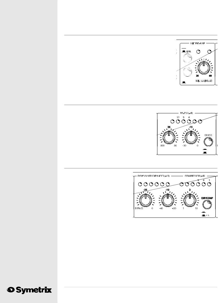
Mic Preamp
MIC/LINE |
Selects between the Mic input (switch in) and |
|
Switch Line input (switch out). |
-15 dB PAD |
Inserts 15 dB pad for strong mic signals. |
Switch |
|
MIC GAIN |
Sets the gain of the mic preamp for best compro- |
|
mise between signal-to-noise ratio and headroom. |
CLIP LED |
Monitors inputs (mic and line) for clipping. |
|
Illuminates 3 dB below the actual clip point. |
PHANTOM |
Illuminates when 48V phantom power is present at |
|
the microphone input connector. LED The phantom |
|
power switch is located on the rear panel. |
 MIC
MIC  PHANTOM
 15 PAD
NORM
DE-Esser
FREQUENCY |
Sets the rolloff (cutoff) frequency of |
|
the de-esser. |
THRESHOLD |
Sets the threshold level for the de-esser. |
|
Signals above this level cause de-esser |
|
action, signals below do not. |
IN/OUT Switch |
Hard-wire bypasses the de-esser. The |
|
de-esser is active when this switch is in. |
LED Display |
Indicates the amount of de-esser |
|
activity at any instant in time. |
15 |
4 |
2 |
IN
FREQUENCY THRESHOLD
OUT
Downward Expander / Compressor
EXP THRESH Sets the threshold level for the downward expander. Signals below this threshold are downward expanded (reduced in level).
COMP THRESH Sets the threshold level for the compressor. Signals above this threshold cause gain reduction in the compressor.
20 |
16 |
12 |
9 |
6 |
3 |
20 |
16 |
12 |
BYPASS |
|
1 |
|
|
EXP THRES |
COMP THRES |
COMP RATIO |
|
IN |
|
||||
|
|
|||
|
|
|
|
|
COMP RATIO |
Sets the compression ratio of the compressor. |
EXP/COMP |
Defeats the downward expander / compressor. This is not a hard-wire bypass. |
IN/OUT Switch |
|
DOWNWARD |
Indicates the amount of downward expander activity (gain reduction) at any |
EXPANDER |
instant in time. |
LED Display |
|
COMPRESSOR |
Indicates the amount of compressor activity (gain reduction) at any instant in |
LED Display |
time. |
6

Parametric EQ Low
FREQUENCY |
Varies the center frequency of the |
LOW EQ |
|
|
low-frequency equalizer from |
|
|
|
16Hz to 500 Hz. |
|
|
BANDWIDTH |
Varies the bandwidth of the low- |
|
|
|
frequency equalizer from 0.3 to 4 |
|
|
|
octaves. (Q=4.8 to 0.27). |
|
|
CUT/BOOST |
Sets the degree of boost or cut; |
|
|
|
±15 dB. |
BANDWIDTH |
CUT/BOOST |
|
FREQUENCY |
Parametric EQ Mid
FREQUENCY Varies the center frequency of the mid-frequency eq from 160 Hz to 6300 Hz.
BANDWIDTH Varies the bandwidth of the mid-frequency eq from 0.3 to 4 octaves. (Q=4.8 to 0.27).
CUT/BOOST Sets the degree of boost or cut; ±15 dB.
MID EQ
FREQUENCY BANDWIDTH CUT/BOOST
Parametric EQ High
FREQUENCY Varies the center frequency of the equalizer from
680 Hz to 22 kHz.
BANDWIDTH Varies the bandwidth of the high-frequency equalizer from 0.3 to 4 octaves. (Q=4.8 to 0.27).
CUT/BOOST Sets the degree of boost or cut; ±15 dB.
IN/OUT Switch Hard-wire bypasses the entire equalizer.
Output Section
GAIN |
Sets the overall gain of the 528E’s output |
|
over a ±15 dB range. Note: the actual |
|
adjustment point is in the expander/ |
|
compressor's VCA, which is pre-EQ. |
VOICE |
Inserts speech waveform asymmetry |
SYMMETRY |
correction into the signal path. |
OUTPUT LED |
Indicates the peak output level of the |
|
528E relative to the balanced output. |
|
0 VU Display on the display corresponds |
|
to +4dBu at the balanced output. For |
|
unbalanced applications, the actual output |
|
level is 6 dB lower than that shown by the |
|
display. |
-15
GAIN (dB) |
|
POWER |
|
|
|
Note |
If the internal mic-level output switch has been depressed, the output level is |
|
-40 dBu when the display indicates 0 VU. |
POWER LED |
Indicates the presence of AC power. |
7
528E
528E
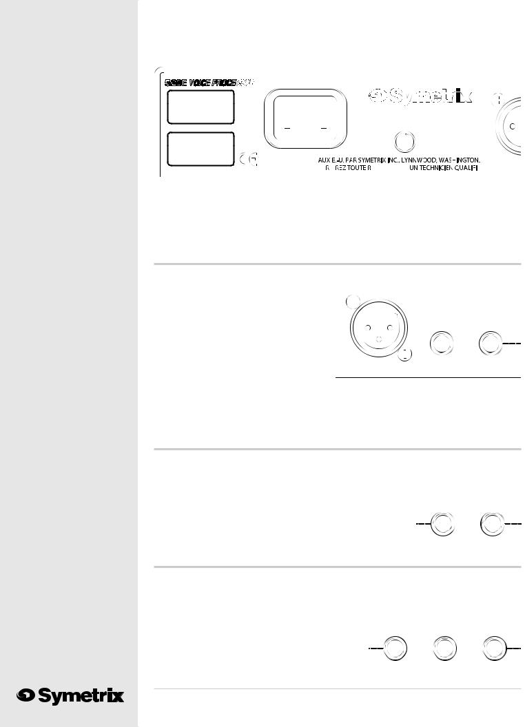
Rear Panel Overview |
Chapter 5 |
|
|
|
|
15 WATTS MAXIMUM |
MANUFACTURED IN THE USA BY |
BALANCE |
|
|
THIS UNIT CONTAINS NO
USER SERVICEABLE PARTS.
POWER
FABRIQU
F |
PARATION ½ |
. |
SERIAL NUMBER Please note the serial number for future reference. Should your 528E ever require service, Symetrix Customer Service will need this information in order to process your repair request.
AC POWER INPUT IEC-power connector. Connect only to appropriate AC power source. Refer to rear-panel marking for correct AC source voltage.
OUTPUT STAGE
BALANCED XLR-male. Balanced, line-level OUTPUT output. This output may be
converted to mic-level via an internal switch. Refer to Appendix C.
UNBALANCED TRS phone jack (wired for OUTPUT unbalanced operation) This is the
unbalanced, line-level output of the 528E. This jack is unaffected by the internal switch (see preceding paragraph).
BALANCED OUTPUT
OUTPUT STAGE
UNBALANCED
OUTPUT INPUT
OUTPUT TRS phone jack (wired for unbalanced operation). This is the input to the output STAGE stage and interrupts the signal coming from the remainder of the 528E.
INPUT
EQUALIZER
OUTPUT |
TRS phone jack (wired unbalanced). This is the |
|
|
|
output of the equalizer. This jack does not interrupt |
|
|
|
the signal flow to the 528E’s output stage. |
EQUALIZER |
|
INPUT |
TRS phone jack (wired unbalanced). This is the |
OUTPUT |
INPUT |
|
|
||
input to the equalizer. This jack interrupts the signal from the Expander/Compressor.
EXPANDER/COMPRESSOR
OUTPUT TRS phone jack (wired unbalanced). This is the output of the Expander/ Compressor. This jack does not interrupt the signal flow to the 528E’s equalizer.
SIDECHAIN TRS phone jack wired as an insert jack (Tip=return, Ring=send). Use this jack to access the compressor/expander’s sidechain.
EXPANDER/COMPRESSOR
OUTPUT |
SIDECHAIN |
INPUT |
TIP=RETURN
RING=SEND
8
INPUT |
TRS phone jack (wired unbalanced). This is the input to the Expander/ |
|
Compressor. This jack interrupts the signal from the De-Esser. |
De-Ess
OUTPUT |
TRS phone jack (wired unbalanced). This is the |
|
output of the De-Esser. This jack does not |
|
interrupt the signal flow to the 528E’s Expander/ |
|
Compressor. |
INPUT |
TRS phone jack (wired unbalanced). This is the |
|
input to the De-Esser. This jack interrupts the |
|
signal from the Mic/Line inputs. |
DE-ESS
OUTPUT INPUT
Preamp
|
|
|
|
|
|
|
|
PREAMP STAGE |
TRS phone jack (wired unbalanced). This is the output of the Mic/Line preamp. |
||
OUTPUT |
This jack does not interrupt the signal flow to the 528E’s De-Esser. |
||
LINE INPUT |
XLR Connector. 10-kilohm balanced bridging line input intended for signals |
||
|
ranging from -10 dBu to +4 dBu. |
||
MIC INPUT |
XLR connector. Balanced input suitable for low-impedance microphones. 48V |
||
|
phantom powering available. |
||
PHANTOM POWER Pushbutton switch enabling Phantom Power on Mic Input.
9
528E

528E
Voice Processing Tutorial |
Chapter 6 |
|
|
|
|
Basics
The Symetrix 528E Voice Processor combines Symetrix’ program controlled interactive dynamic range processing technique with a three-band parametric equalizer. This combination of processors is similar to a voiceover or vocal signal processing chain as used in a recording or voiceover studio. “Program controlled” means the 528E’s dynamic range processor section analyzes incoming signals, then adjusts its release time to match the transient characteristics of those signals.
This chapter of the manual contains a tutorial on the basics of dynamic range processing and equalization: the two key ingredients in the 528E. The tutorial information is intended to provide a background for the information found in the remainder of this manual.
Dynamic Range Processing
Dynamic range processors are used to fit wide-range signals into narrow-range transmission or storage channels. The dynamic range of acoustical signals found in real life usually far exceeds our capacity to store or transmit them. Confronted with this dilemma, audio engineers usually reach for a compressor/limiter or downward expander as a means to fit two-pound signals into one-pound bags.
Compressor/limiters respond quickly to transients, and gently to normal speech level changes which keeps overall levels in check. The downward expander’s operation is the inverse of the compressor/ limiter which prevents “pumping” and “breathing” even when high ratio compression is necessary. Because the compressor/limiter and the downward expander are interactive, the 528E always responds appropriately, while providing automatic control over a wide range of input levels.
Strictly speaking, the terms compressor and limiter refer to two different devices. Oftentimes the two are combined into a single device called a compressor/limiter. Compressor/limiters usually perform as either a compressor or a limiter, but not both at once. Functionally, a compressor/limiter is a device that lets the user define, or predetermine, the maximum level of an audio signal.
Expanders and gates are the functional opposites of compressors and limiters. Compressors continuously reduce the dynamic range of signals that are above threshold, while expanders continuously increase the dynamic range of signals that are below threshold. Limiters can be thought of as very high ratio compressors, and gates can be thought of as very high ratio expanders.
In addition to their roles as remedial signal processors, compressors also have a creative role. You can use a compressor to increase the apparent sustain of a guitar, increase apparent loudness, improve the consistency of a bass by removing or reducing level changes, and many other things.
Generally speaking, the settings for these applications are somewhat extreme, so experimentation is the name of the game.
Defining Dynamic Range
To begin a discussion of dynamic range processors it’s necessary to have a working definition of dynamic range. The term is really self-descriptive, but has two distinctly different uses:
1.To describe the actual range of signal fluctuations that are going through the equipment.
2.To define the maximum allowable range of signal fluctuations that can be put through the equipment.
The usual unit of measure for audio signals is the decibel (dB).
Dynamic Range as a Specification
The maximum usable range of operation for a particular circuit or piece of gear is the distance in dB between the noise floor and the maximum output level. In this context, dynamic range is used as an equipment specification.
Noise floor is defined as the lower limit of a circuit’s operating level, and is a function of its selfgenerated electrical noise. Very noisy circuits have a high noise floor, quiet circuits have a low noise floor. All circuits have a noise floor, unless they are operating at -460 degrees Fahrenheit (absolute
10

zero). The maximum output level of a circuit is the upper limit of the operating level, and is the level at which clipping begins and is a function of the internal power supply voltage. To put levels in perspective they must be referenced to some nominal operating level, like 0 dBm. That’s why noise specs are stated as negative numbers.
In the case of the 528E, noise is referred to the input, and stated as equivalent input noise (EIN). The noise specification is given this way because the gain of the 528E’s input stage is variable, so the actual signal-to-noise performance of the unit becomes a function of how much gain is used in the preamp. To find the signal-to-noise ratio at 0 dBm output, algebraically add the preamp gain to the EIN.1
Since maximum output level is usually greater than 0 dBm, it’s stated as plus something. The 528E’s maximum output level is +18 dBm into a 600-ohm balanced load, which is 18 dB above 0 dBm. The difference between the noise floor and the onset of clipping is the dynamic range. To find the 528E’s dynamic range with 50 dB preamp gain, subtract -89 from 18. The result (113 dB) is the dynamic range.
Dynamic Range of Sounds and Signals
The other definition of dynamic range describes actual level changes, or the range over which signals fluctuate. The signals under discussion here are electrical representations of sounds, so it follows that sound has dynamic range. The dynamic range of the human voice, from a whisper to a shout, is well over 100 dB. Thus, the microphone converts the sound pressure of a voice going from a whisper to a shout into an electrical output signal having the same dynamic range.
Why Dynamic Range Processors are Necessary
For signals to stay below distortion and above noise, their actual dynamic range must be kept within the specified dynamic range of the circuits through which those signals flow. Unfortunately, the actual dynamic range of real world signals often exceeds the available dynamic range of even the best equipment.
For example, the dynamic range of the best analog tape recorders is around 80 dB, while digital recorders top out at around 96 dB. As good as these machines are, there’s still not quite enough room for very wide dynamic range signals. In order to maintain a 60 dB signal-to-noise ratio (to keep the signals 60 dB above the noise floor), the dynamic range of signals stored on the analog tape machine would have to be restricted by 20 dB, while the digital recorder would be restricted by 36 dB.
A compressor or limiter is often used to reduce dynamic range by setting an upper limit on the larger signals. In some cases, it’s better to put processing to work on the lower end of the dynamic range than on the upper end. In other words, instead of reducing the amount of change at the upper end of the dynamic range with a compressor or limiter, increasing the amount of change at the lower end of the dynamic range with a downward expander or gate.
Compressors are to Downward Expanders as Limiters are to Gates
Compressors reduce the dynamic range of their output whenever the input signal is above threshold, while downward expanders increase the dynamic range of their output whenever the input signal is below threshold.
Compressors, limiters, expanders, and gates increase or decrease signal levels by some ratio. Compressors usually have an adjustable ratio, the ratio of the input level to the output level, which is generally user-adjustable. A compressor operating with a 2:1 ratio allows only a 1 dB increase in output level for every 2 dB increase in input level.
Limiters usually have a nonadjustable ratio that is very high (greater than 10:1). At 10:1, the limiter allows only a 1 dB increase in the output level for every 10 dB increase in the input level. Limiters can be thought of as high ratio, high threshold compressors. They are intended to “stay out of the way” until the level goes above threshold. However, above threshold their action is very definite.
11
528E

528E
The Threshold Concept
The threshold is the level at which a dynamic range processor’s activity begins. In operation, the dynamic range processor’s sensing circuitry constantly “looks at” the incoming signal and compares it to a reference level, which is called the threshold level. In practice that reference level is set by the operator via the threshold control. Remember, compressors and limiters respond when signals at the input are above threshold, while downward expanders and gates respond only when signals at the input are lower than the defined threshold.
The VCA - Voltage Controlled Amplifier
The action of any dynamic range processor depends on some method of changing the gain based on some external signal. Typically this takes the form of a special sort of amplifier whose gain is controlled by a DC voltage. That part of the circuit is called a voltage controlled amplifier, or VCA. Inside the 528E a separate buffered audio signal is sent to a group of circuits that comprise the detector (envelope follower to you synthesists). The detector circuits turn the AC audio signal into a DC control voltage, which is sent to the VCA under the direction of the front panel controls.
Linear vs. Downward Expanders
Expander operation is easily misunderstood unless it’s remembered that what’s being expanded is the dynamics, or changes, of signals passing through the circuit. Expanders come in two very different types: linear, and downward.
Linear expanders increase the dynamic range of all signals, no matter what their actual level. The linear expander simply makes all changes greater by some ratio, which is sometimes user adjustable. In the real world, linear expanders aren’t too practical because clipping occurs when signals just below maximum output level are expanded.
For instance, an unprocessed signal 3 dB below clipping that increases 2 dB won’t distort, because it’s still 1 dB below maximum. But if that same signal is passed through an expander operating at a 1:2 ratio, the same 2 dB change at the expander’s input becomes a 4 dB change at its output. However, that signal would be 1 dB over maximum, causing distortion. Linear expanders must be used with care, because very few systems have enough headroom to handle the upward dynamic range increase they produce.
The kind of processor most commonly called an expander is really a downward expander, because it only affects signals below threshold. This gives the operator control over the expander’s activities, allowing it to be used to expand the usable dynamic range of the system without running out of headroom.
Note: in the interests of clarity and brevity, the term expander will be defined as a downward expander from this point forward in this manual.
How Expanders Increase Usable Dynamic Range
The lower limit restriction of a system is the noise floor, which is usually well below the 528E’s lowest expander threshold (-50 dBu). It’s important to keep in mind that while the signal levels may change greatly, the noise usually doesn’t change very much. The action of the expander increases the dynamic range of all signals below threshold. This action increases the apparent loudness of signals, while decreasing the apparent loudness of the noise.
For example, an expander operating at a ratio of 1:2 will cause an input signal that falls 10 dB below threshold to fall 20 dB at its output. The downward action of the expander reduces the noise floor by the same ratio applied to the signal. Since the relationship between the signal and the noise stays the same, the noise is reduced 20 dB by the action of expander, which is responding to a 10 dB drop in the signal with its 1:2 ratio.
12
 Loading...