


SYMEO LPR
®
Product: LPR®-2DB
Product Documentation

Symeo LPR®-System
LPR®-2DB
Product Documentation
CONTENT
1 GENERAL ........................................................................................................ 9
1.1 Safety Instructions ................................................................................................... 9
1.2 Installation ............................................................................................................... 9
1.3 Repairs.................................................................................................................... 9
1.4 Transport and Storage ............................................................................................ 9
1.5 Power Supply .........................................................................................................10
1.6 Setup and Operation ..............................................................................................10
1.7 System Extensions and Accessories ......................................................................10
1.8 Additional Instructions Regarding Compact Type and Integral Type Stations .........11
2 INTRODUCTION ............................................................................................ 12
2.1 Details ....................................................................................................................12
2.2 Overview of Files ....................................................................................................12
2.3 Project Planning .....................................................................................................15
3 SYSTEM DESCRIPTION ................................................................................ 18
3.1 Technical Data .......................................................................................................18
3.2 Operating Mode .....................................................................................................19
3.2.1 Operation Mode 1: Basic Cell ..........................................................................19
3.2.2 Operation Mode 2: Managed Cell ....................................................................20
3.2.3 Operation Mode 3: TDOA ................................................................................21
3.3 Vehicle Model.........................................................................................................22
3.3.1 Hover-Track ....................................................................................................23
3.3.2 Vehicle-Track ..................................................................................................23
3.4 System Design .......................................................................................................23
3.4.1 2D Positioning .................................................................................................24
4 HARDWARE ................................................................................................... 26
4.1 System components – Overview ............................................................................26
4.2 LPR-2DB Station (mobile station) ...........................................................................26
4.2.1 Overview compact station ...............................................................................26
4.2.2 Technical data compact station .......................................................................26
4.2.3 Station BSB000313, BSB000319 ....................................................................27
4.2.4 Station BSB000603, BSB000604, BSB000605, BSB000606 ...........................28
4.2.5 Lumberg Connector Type 0233 08 ..................................................................29
General
Copyright © Symeo 2012
Page 2 of 132

Symeo LPR®-System
LPR®-2DB
Product Documentation
4.3 Cables for Compact Station ....................................................................................29
4.3.1 Cable for Power Supply ...................................................................................29
4.3.2 Recommended Cable Types HARTING Push Pull Connector .........................31
4.4 Connector box ........................................................................................................ 31
4.4.1 Example: Connector Box .................................................................................32
4.5 LPR-2DB Integral Station (fixed mounted unit) .......................................................33
4.5.1 Technical Data: LPR-2DB Integral Station .......................................................33
4.5.2 Components of LPR-2DB Integral Station .......................................................34
4.6 LPR Antennas for Compact Station (mobile unit) ...................................................34
4.6.1 Mounting devices of LPR Antennas .................................................................35
5 INSTALLATION .............................................................................................. 37
5.1 Installation of the LPR-2DB Station (mobile unit) ....................................................37
5.2 Installation of the LPR-2DB Integral Station ...........................................................38
5.2.1 Electrical Interface ...........................................................................................38
5.2.2 Installation .......................................................................................................39
5.2.3 Allocation of LPR-2DB Integral Stations and Installation Points .......................41
5.3 Installation of LPR antennas ...................................................................................41
5.3.1 Connection of antenna cables to the mobile units (LPR-2DB Station) .............41
5.3.2 Mounting of LPR antennas ..............................................................................42
5.3.3 Notes for mounting position of LPR antennas on the mobile unit .....................43
6 COORDINATE SYSTEM ................................................................................ 46
6.1 Survey Instructions for the LPR-2DB Integral Station .............................................46
6.1.1 Coordinate system of LPR-2DB Integral Station ..............................................46
6.1.2 Reference point of LPR-2DB Integral Station ..................................................47
6.1.3 Orientation of LPR-2DB Integral Station ..........................................................48
6.1.4 Formatting of coordinates ................................................................................49
6.2 Surveying of LPR-2DB Compact Station on mobile unit .........................................50
6.2.1 Reference system for vehicle type: forklift .......................................................50
6.2.2 Reference system for vehicle type: Van Carrier...............................................50
6.2.3 Reference system for vehicle type: passenger car ..........................................51
6.2.4 Reference system for vehicle type: crane/ trolley ............................................52
6.3 Surveying of LPR antennas ....................................................................................52
6.3.1 Formatting of coordinates ................................................................................53
7 COMMISSIONING .......................................................................................... 55
General
Copyright © Symeo 2012
Page 3 of 132

Symeo LPR®-System
LPR®-2DB
Product Documentation
7.1 Check list installation and surveying .......................................................................55
7.1.1 Cells, Integral stations .....................................................................................55
7.1.2 LPR-2DB Station (Mobile units) .......................................................................56
7.1.3 Formatting of coordinates ................................................................................56
7.1.4 Folders structure .............................................................................................56
7.2 Editing of configuration files for the DSP ................................................................56
7.2.1 File basestation_config.txt ...............................................................................57
7.2.2 File stationXXM_config.txt ...............................................................................57
7.2.3 File stationXXY_config.txt ...............................................................................58
7.3 Upload of configuration files for the DSP ................................ ................................58
7.3.1 Connection with LPR mobile unit (type: compact) via TCP/IP ..........................59
7.3.2 Connection with LPR mobile unit (type: compact) via RS232 ..........................60
7.3.3 Upload DSP configuration file for LPR mobile unit (base station) ....................61
7.3.4 Upload DSP configuration file for master transponder unit ..............................62
7.3.5 Upload DSP configuration file for transponder unit ..........................................65
7.4 Editing of configuration files for Fusion Engine .......................................................67
7.4.1 fusion.ini ................................................................................................ ..........68
7.4.2 field.ini .............................................................................................................69
7.4.3 LPR_B.ini ........................................................................................................70
7.4.4 LoadPos.ini .....................................................................................................71
7.4.5 Customer.ini (or Symeo_2D.ini) ......................................................................71
7.5 Upload configuration files for FusionEngine ...........................................................73
7.5.1 Upload of files via WinSCP..............................................................................73
8 SYMEO MAP .................................................................................................. 78
8.1 Configuration and Connection with Symeo MAP ....................................................78
8.1.1 lpr.ini ...............................................................................................................78
8.1.2 Starting FusionEngine .....................................................................................79
8.1.3 Starting Symeo Map ........................................................................................80
8.1.4 Connection with mobile unit.............................................................................82
8.2 Display of Symeo MAP ...........................................................................................83
8.2.1 Level of Transponders .....................................................................................83
8.2.2 Radius/ Hyperboloids of Transponders ...........................................................83
8.3 Antenna Calibration ................................................................................................83
9 NETWORK SETTINGS ................................................................................... 85
9.1 TCP/IP connection between PC and LPR-2DB station ...........................................85
General
Copyright © Symeo 2012
Page 4 of 132

Symeo LPR®-System
LPR®-2DB
Product Documentation
9.2 Open Web Server ..................................................................................................86
9.3 Settings ..................................................................................................................87
9.3.1 LAN .................................................................................................................88
9.3.2 Network ...........................................................................................................89
9.3.3 Serial-to-Ethernet ............................................................................................90
9.3.4 Remote Access ...............................................................................................92
9.3.5 Miscellaneous ................................................................ .................................93
9.3.6 Special functions .............................................................................................93
9.3.7 Accept settings/ System reboot .......................................................................94
9.4 System status.........................................................................................................94
9.5 Diagnostics ............................................................................................................96
9.6 Update Firmware ....................................................................................................97
9.6.1 Step 1 – File system ........................................................................................98
9.6.2 Step 2 – Linux Kernel .................................................................................... 100
9.6.3 Step 3 – User space (optional) ...................................................................... 103
9.6.4 Step 4 – Restart ............................................................................................ 103
9.7 System Log .......................................................................................................... 104
10 SYMEO 2D PROTOCOL .............................................................................. 106
10.1 Introduction / Basics ............................................................................................. 106
10.1.1 Configuration file Symeo_2D.ini .................................................................... 106
10.2 Binary format of the protocol ................................................................ ................ 108
10.2.1 Data types ..................................................................................................... 108
10.2.2 Byte Stuffing .................................................................................................. 108
10.2.3 General Structure .......................................................................................... 109
10.2.4 Data fields ..................................................................................................... 110
10.3 ASCII format of the Protocol ................................................................................. 116
10.3.1 Data Types .................................................................................................... 116
10.3.2 General Structure .......................................................................................... 116
10.3.3 Data fields ..................................................................................................... 117
10.4 Bit Mask SELECTED-FIELDS .............................................................................. 124
10.5 CRC Calculation ................................................................................................... 125
10.6 Error Codes .......................................................................................................... 126
10.6.1 Overview ....................................................................................................... 126
10.6.2 Error codes ................................................................................................... 126
10.6.3 LPR-B address .............................................................................................. 128
General
Copyright © Symeo 2012
Page 5 of 132

Symeo LPR®-System
LPR®-2DB
Product Documentation
11 APPENDIX A: AGENCY CERTIFICATIONS ................................................ 129
United States (FCC) and Canada (Industry Canada) ...................................................... 129
United States (FCC)........................................................................................................ 129
Canada (Industry Canada) .............................................................................................. 131
General
Copyright © Symeo 2012
Page 6 of 132
Symeo LPR®-System
Version
Date
Description
3.17
2009-05-20
Initial release
3.18
2009-07-07
Added documents to one document
3.19
2010-02-01
Updated SYMEO Map and FusionEngine description
4.00
2010-06-30
Completely revised
4.01
2012-04-20
FCC Appendix added
This symbol appears before instructions that must be followed at all times.
Failure to comply with these instructions will result in personal injury.
This symbol appears before instructions that must be followed at all times.
Failure to comply with these instructions will result in damage to equipment.
This symbol appears before information of particular importance.
LPR®-2DB
Product Documentation
The documentation for the LPR Local Positioning Radar System is published by:
SYMEO GmbH
Prof.-Messerschmitt-Str. 3
85579 Neubiberg
www.symeo.com
If you have any questions or suggestions, please contact:
Email: info@symeo.com
phone: +49 89 660 7796 0
Copyright © Symeo GmbH 2009
All rights reserved
HISTORY
VERWENDETE SYMBOLE
The following symbols are used in the documentation:
All rights reserved, particularly those relating to the translation, reprinting, and reproduction
by photocopying or similar processes of all or part of the documentation.
All rights reserved, particularly for purposes of the award of patents or submission of utility
models.
Delivery options and technical changes reserved.
Published by SYMEO GmbH
General
Copyright © Symeo 2012
Page 7 of 132

Symeo LPR®-System
LPR®-2DB
Product Documentation
General
Copyright © Symeo 2012
Page 8 of 132
Symeo LPR®-System
LPR®-2D systems are purely tracking and assistance systems. They
therefore do not satisfy special requirements for personal safety, e.g.
performance level c.
Follow the safety instructions in the operating instructions for the device
and the additional documentation!
All installation, repair and servicing work must be carried out by qualified
and trained technicians!
Repairs to the device must be carried out by authorized technicians.
Unauthorized opening and incorrect repairs could result in severe
danger to the user (danger of electric shock, radiated energy, fire
hazard).
Use the original packaging or other suitable packaging for returns and
whenever the system is to be transported. This ensures protection from
crushing, impacts, moisture and electrostatic discharge.
During setup and before operation, refer to the instructions for
environmental conditions included in the operating instructions for the
device.
Route the wires in such a way that they do not cause a hazard and are
not damaged. When connecting the wires, refer to the corresponding
instructions in the operating instructions for the device.
Do not drop the device and do not expose it to strong vibrations.
LPR®-2DB
Product Documentation
1 General
1.1 Safety Instructions
Keep these safety instructions and other documents together with the device.
1.2 Installation
1.3 Repairs
1.4 Transport and Storage
Copyright © Symeo 2012
Page 9 of 132
General
Symeo LPR®-System
A safety-inspected power cable that satisfies the regulations of the
country of use is required for the device. Devices with metal housings
must only be connected to a grounded, shock proof socket.
The device must not be operated unless the nominal voltage of the
device matches the local supply voltage. Check the supply voltage of
the device in stationary devices.
When connecting and disconnecting wires, refer to the instructions in
the operating instructions for the device.
Do not use any damaged wires (damaged insulation, exposed wires). A
faulty wire poses a risk of electric shock or fire hazard.
During installation, make sure that no objects or fluids get inside the
device (risk of electric shock, short circuit).
In emergencies (e. g. if there is damage to the housing, control
elements or the mains cable, if fluids or foreign bodies have infiltrated
the equipment), switch off the power supply to the device immediately
and notify your SYMEO Service.
Protect the contacts of all of the device's sockets and plugs from static
electricity. Do not touch the contacts. If it is ever necessary to touch the
contacts, take the following precautionary measures: Touch a grounded
object or carry a ground strap before touching the contacts. This will
divert static charges.
Proper operation (in accordance with IEC60950/EN60950) of the device
is only assured if the housing and integral covers for mounting slots are
fully installed (electric shock, cooling, fire protection, noise suppression).
If necessary, refer to the corresponding instructions in the operating
instructions for the device.
In the case of high outside temperatures and intense, direct solar
radiation or other radiant heat, it may be necessary to provide a sun or
heat shield.
Data links to peripheral devices must be provided with adequate
shielding.
For LAN cabling, the requirements in accordance with EN 50173 and
EN 50174-1/2 apply. Use of either a Category 5 shielded cable for
10/100 Ethernet or Category 5e shielded cable for gigabit Ethernet is a
minimum requirement. The specifications of standard ISO/IEC 11801
LPR®-2DB
Product Documentation
1.5 Power Supply
1.6 Setup and Operation
1.7 System Extensions and Accessories
General
Copyright © Symeo 2012
Page 10 of 132
Symeo LPR®-System
must be complied with.
The warranty shall be voided if you cause defects to the device by
installing or exchanging system extensions.
The Compact type LPR station must not be opened except for
installation. The Compact station contains no serviceable components.
When opening, ensure that no fluid gets into the housing. When sealing
the station, ensure that the seal is included in the cover and that the
Compact station is completely closed. Otherwise, moisture can
penetrate the station and damage it.
In order to install the Integral type LPR station, the hood must be
detached from the serviceable components. Refer also to the
instructions on installing the transponder.
Please take note of the safety and operating instructions in the
operating instructions for the system in which you want to install the
component.
LPR®-2DB
Product Documentation
1.8 Additional Instructions Regarding Compact Type and Integral Type Stations
Copyright © Symeo 2012
Page 11 of 132
General
Symeo LPR®-System
This symbol appears before information of particular importance.
This symbol appears before instructions that must be followed at all
times. Failure to comply with these instructions will result in damage to
equipment.
This symbol appears before instructions that must be followed at all
times. Failure to comply with these instructions will result in personal
injury.
This symbol appears if the following sub-chapter describes difference in
the operating mode. An overview about the operating modes is given in
chapter 3.2.
LPR-2DB Station
(Mobile unit / base
station):
- master_basestation_config.txt or Basestation_config.txt
(depending on the selected operating mode)
LPR-2DB Integral
Stations
(transponders):
- STATION010_CONFIG.TXT
- STATION011_CONFIG.TXT
- STATION012_CONFIG.TXT
- STATION013_CONFIG.TXT
- STATION014_CONFIG.TXT
- STATION015_CONFIG.TXT
Master LPR-2DB
Integral Station
(optional):
- station01M_config.txt (depending on the selected operating
mode)
Symeo MAP (optional)
- SYMEO Map XP Installer
FusionEngine:
- FusionEngine.exe
- const_pos.ini
- field.ini
- fusion.ini
- LPR_B.ini
- movingcell.ini
- multi_cell.ini (TDOA)
- HoverTrack.ini / VehicleTrack.ini or TDOA.ini (depending on
LPR®-2DB
Product Documentation
2 Introduction
2.1 Details
2.2 Overview of Files
Copyright © Symeo 2012
Page 12 of 132
Introduction
Symeo LPR®-System
the selected model, application and operation mode)
- symeo_map.ini
- symeo_2D.ini
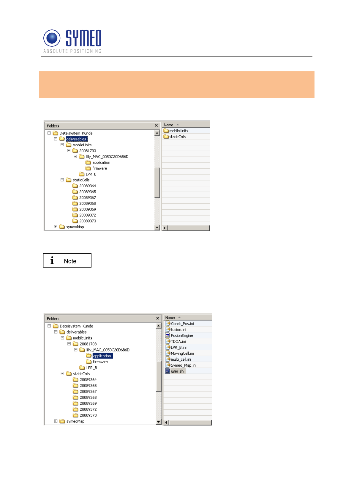
Figure 1- folder structure
The folder “mobileUnits”
contains all files for the
vehicles. The folder
“staticCells” contains all files
for the LPR-2DB Integral
Station including the master
LPR-2DB Integral Station. The
folder name for all LPR stations
is named with the serial
number.
To allocate the stations for the customer, it makes sense to create a
text-file that describes the function of that LPR station, i.e.
“forklift_123_customer.txt”.
If it is later necessary to replace a LPR unit (e.g. due to a defect) you
can find easily the necessary configuration files for the appropriate
station.
Folder for the files of the
FusionEngine
LPR®-2DB
Product Documentation
All files are delivered in the structure shown in Figure 1 (“deliverables” and “symeoMap”).
Copyright © Symeo 2012
Page 13 of 132
Introduction

Symeo LPR®-System
Folder for the files of the
firmware for the mobile unit
Folder for the configuration
files of the DSP for the mobile
unit
Folder for the configuration
files of the DSP for the
transponder unit
LPR®-2DB
Product Documentation
Copyright © Symeo 2012
Page 14 of 132
Introduction

Symeo LPR®-System
ToDo
Description
Responsible
Relevant
chapter
1
Definition of measurement
area/cell
Analyzing of layout,
pictures, definition of
mounting positions
Customer
provides
information to
Symeo
--2
Definition of local
coordinate system, point
of origin
Local Coordinates
available? Coordinates of
light towers available?
Customer
---
3
Definition of operating
mode
3 operating modes are
available. Operating mode
depends on the number of
vehicles and the number of
cells
Symeo
Chapter 3.2
4
Definition of vehicle model
HoverTrack-model or
VehicleTrack-model
Symeo
Chapter 3.3
5
Definition of antenna
positions and position of
mobile unit on the vehicle
for mounting
Defining mounting position
of 1, 2, 3 or 4 antennas on
the vehicle
Customer/
Symeo
Chapter 5.3
6
Definition of the height of
the antenna above ground
level
The height of the top of the
antennas above ground
has to be calculated to set
the appropriate height for
the mounting of the
transponders, height of
transponders ideally
0.5meters over antennas
level, up to 2.5meters is
possible
Customer
Chapter 6.3
7
Definition of protocol for
interface
Structure of the protocol
can be configured.
Customer/
Symeo (if
information is
provided)
Chapter 0
8
Mounting of the LPR-2DB
Integral Station on the LTs
Mounting of the LPR-2DB
Integral Station (labeled
XX0, XX1, XX2, XX3, XX4,
XX5 and Master XXM)
according to the files VisioLPR_CellPlanning.pdf and
Customer
Chapter 5.2
LPR®-2DB
Product Documentation
2.3 Project Planning
The planning from identifying the position for the transponders to the commissioning with
Symeo MAP is separate into intermediate steps. In the following all possible steps are listed
with refer to the relevant chapter in this document.
Copyright © Symeo 2012
Page 15 of 132
Introduction

Symeo LPR®-System
CellPlanning.xlsx
9
Mounting of the antennas
Mounting on defined
positions on vehicle with
installation brackets
Customer
Chapter 5.3
10
Mounting of the mobile
station on the vehicle
Mounting of the mobile
station, connection to the 1,
2, 3 or 4 antennas, power
10-36VDC and TCP/IP
Customer
Chapter 5.1
11
Surveying of LPR-2DB
Integral Station
Surveying of the mounted
LPR-2DB Integral Stations
needs to be done to local
coordinates with best
possible accuracy (+- 2cm)
Customer
Chapter 6.1
12
Surveying of vehicle
Surveying of the antenna
positions on to the vehicle.
Depending on the steering
of the vehicle (front and/or
back) the definition of point
of origin on vehicle has to
be set. Offset from point of
origin to container center
has to be determined.
Customer
Chapter
6.2/ chapter
6.3
13
Implementation of
Surveying coordinates in
configuration files
The surveying coordinates
have to be provided in a
data format provided from
Symeo. Transponder
coordinates have to be
implemented into
configuration files for the
master transponder or the
mobile unit. Vehicle
coordinates have to be
implemented into the
configuration files of the
mobile station on the
vehicle.
Customer
Chapter
6.1.4 and
6.3.1
Chapter
7.2.2 or
7.4.2
14
Upload of configuration
files
Configuration files to be
uploaded to the MasterTransponder (operating
mode 2b and 3b) or mobile
unit (operating mode 1, 2a,
2b) and mobile station on
vehicle
Customer/
Symeo
Chapter 7.3
15
Modifying of ini-files for
software FusionEngine
Modification of ini-files
Customer
Chapter 7.4
16
Upload of files for software
fusion engine
Upload of ini-files via
WinSCP
Customer
Chapter 7.5
LPR®-2DB
Product Documentation
Copyright © Symeo 2012
Page 16 of 132
Introduction

Symeo LPR®-System
17
Testing of correct
positions
Testing cell with analyzing
Software Symeo MAP
Customer/
Symeo
Chapter 0
LPR®-2DB
Product Documentation
Copyright © Symeo 2012
Page 17 of 132
Introduction

Symeo LPR®-System
Frequency range
5.725-5.875 GHz
5.725-5.875 GHz
Transmitting power*1
Max. 0.010 W / 10 dBm output on the antenna port
Output power is adjustable
For overall output power antenna gain and cable attenuation
must be added
Range*2
Max. 300 m
Measurement accuracy*2
up to ± 10 cm
Measurement frequency
Max. 20 Hz
Power supply
10-36 V DC
Ambient temperature *2
-40°C bis +70°C
LPR®-2DB
Product Documentation
3 System Description
SYMEO Industrial Local Positioning Radar (LPR) is a system for contactless, real-time
determination of distances and positions.
LPR B 2D is a distance measurement system which is particularly well suited for use in very
harsh, industrial environments, in which other systems such as mechanical rotary encoders
or lasers cannot function for long periods.
The system composes of mobile units and fixed, wall-mounted units at known positions. The
mobile units compute its position using the delay time of the radio-signals between wall
mounted units and the mobile unit.
LPR-2DB has an in-build communication channel to handle all background communication
necessary for operation of the positioning system. LPR-2DB units use the same frequency
band and the same hardware for communicating as for measuring distance. This means that
no external WLAN or cable networks are needed for transmitting measurement values and
other reference data.
The system is organized in a cellular fashion. 4 to 6 wall-mounted units are arranged to form
a group with a unique group-ID and an individual measurement ID ranging from 0-5 for each
wall-mounted unit. For the communication between the mobile unit and the 6 transponders 6
different measurement channels separated in frequency (FDMA) are used, allowing instant
position computation.
For arrangements with more than 6 transponders neighboring cells with different group IDs
can be set up. To separate the communication of neighboring cells different communication
frequency channels can be assigned for different cells. For some system topologies an
additional cell-master is required to handle measurement timing and communication.
3.1 Technical Data
*1
Transmitting power can be adjusted to assure that emission limits at the antenna are within
legal limits, e.g. 25 mW EIRP in the EU and 10 mW EIRP in the US
*2
Depending on the antenna type, mounting position and environment
System Description
Copyright © Symeo 2012
Page 18 of 132
Symeo LPR®-System
Operating Mode
Properties
Mode 1: Basic Cell
6 fixed wall-mounted units [LPR-2DB Integral Station], 1 mobile
unit [LPR-2DB Station]; measurement principle: RTOF (round
trip of flight)
Mode 2a: Managed Cell
6 fixed wall-mounted units [LPR-2DB Integral Station], 1Master,
up to 5 mobile units [LPR-2DB Station] ; measurement principle:
RTOF (round trip of flight); cell coordinates are stored on the
mobile unit(s)
Mode 2b: Managed Cell
6 fixed wall-mounted units [LPR-2DB Integral Station], 1 Master,
up to 10 mobile units [LPR-2DB Station] ; measurement
principle: RTOF (round trip of flight); cell coordinates are stored
at the master
Mode 3a: TDOA
6 fixed wall mounted units [LPR-2DB Integral Station], 1 Master,
no limitation of mobile units [LPR-2DB Station] ; measurement
principle: TDOA (time difference of arrival); cell coordinates are
stored on the mobile unit(s)
Mode 3b. TDOA
6 fixed wall mounted units [LPR-2DB Integral Station], 1 Master,
no limitation of mobile units [LPR-2DB Station] ; measurement
principle: TDOA (time difference of arrival); cell coordinates are
stored at the master
The operating mode is normally set by Symeo after consulting the
customer.
LPR®-2DB
Product Documentation
*3
Temperature inside the housing can range from -40°C to 85°C.
3.2 Operating Mode
There are different system topologies to determine a 2D position with a Symeo LPR® system.
Which operating is best suited depends on the application and the environment. It depends
on the number of mobile units you want to track and on the number of cells which are
necessary to cover the environment.
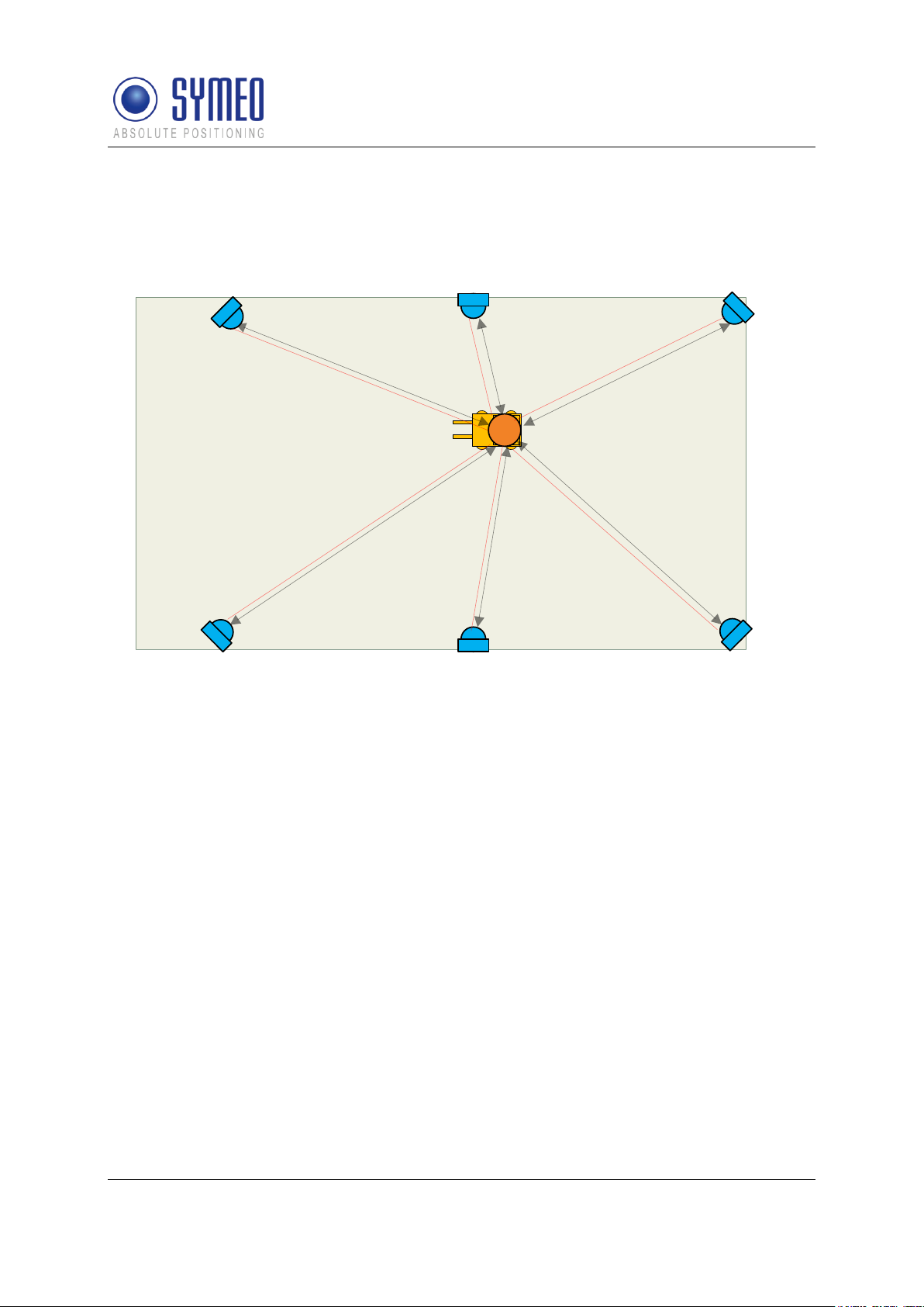
3.2.1 Operation Mode 1: Basic Cell
4-6 fixed mounted units (i.e. at a wall or on light poles) at known positions as basic cell and
one single mobile unit form the setup for mode 1. The fixed mounted units are configured as
reply units or “slave transponders”. Each fixed mounted unit has the same group ID and a
different measurement ID ranging from 0...5. Additionally, the units within the same group
must be set to the same communication channel. The positions of the fixed mounted units
are known to the mobile unit. The measurement of mode 1 is based on the measurement
principle RTOF (Round Trip Of Flight). It is organized as follows:
The mobile unit acts as “master base-station” and sends a measurement command to the
fixed mounted units. The fixed mounted units synchronize to this signal and transmit a return
System Description
Copyright © Symeo 2012
Page 19 of 132
Symeo LPR®-System
2
2
2
2
2
2
1
3
4
4
4
4 4
4
3 3
3
3
3
LPR®-2DB
Product Documentation
signal with precisely known delay and an individual frequency offset corresponding to the
fixed mounted unit measurement ID. The mobile unit computes the round-trip time-of-flight
and therefore the 1D distance to each transponder. Finally, the mobile unit calculates of all
single 1D distances a 2D position.
Figure 2 - System setup for mode 1
1: Mobile unit
2: Wall-mounted unit
3: Communication channel (commands)
4: Broadband measurement signals
3.2.2 Operation Mode 2: Managed Cell
Mode 2 is used when several mobile units are present at the same time within the cell. In this
case the measurement intervals between the mobile units are synchronized. This is done by
using the setup of mode 1 and an additional master transponder for coordination. The master
transponder assigns the measurement slots for different mobile units. The mobile unit no
longer initializes the measurement and simply acts as base-station. The measurement of
mode 2 is based on the measurement principle RTOF (Round Trip Of Flight). The detailed
measurement procedure is as follows:
The master transponder repeatedly broadcasts his group-ID. Base-stations in range reply to
this broadcast with their ID. The master transponder keeps a list of active base-stations in
range, assigns measurement slots to the stations and broadcasts them to the individual
stations in range. The base-station then transmits the broadband measurement signal and
computes its position as described in mode 1.
Measurement rate for the stations present can be set to equal distribution for all mobile units
or to a preferred channel with maximum measurement rate for one base-station and slower
measurement rate for the remaining stations.
Copyright © Symeo 2012
Page 20 of 132
System Description

Symeo LPR®-System
3
2
2
2
2
2
2
1
4
5
5 5
5 5
5
4
4
LPR®-2DB
Product Documentation
If desired the master transponder can store the coordinates of the cell (mode 2b). The
master transponder then repeatedly broadcasts his coordinates and all base-stations in
range receive the data. Alternatively the coordinates can be kept on the mobile unit
permanently as in mode 1 (mode 2a).
Finally, depending on the master-transponder type, the position data of the mobile units can
also be transmitted to the master transponder and can be retrieved by the user.
Figure 3 - System setup for mode 2
1: Mobile unit
2: fixed mounted units
3: Master unit
4: Communication channel (commands)
5: Broadband measurement signals
3.2.3 Operation Mode 3: TDOA
Sometimes many mobile units are present in a cell, or measurement of the position of mobile
units at exactly the same time is desired. Using mode 3, only the fixed mounted units
transmit broadband measurement signals. The mobile unit receives these signals and
computes its position from the time-differences of the signals.
Mode 3 has the same basic hardware as mode 2, but the organization of the measurement is
completely different:
The master transponder sends a broadband synchronization signal preceded by the group ID
of the cell. The slave transponders precisely synchronize to this signal and in turn each
transponder transmits the broadband measurement signal. All base-stations within the cell
receive the signal and compute the time-difference between the received signals. The timedifference is used to obtain the position.
System Description
Copyright © Symeo 2012
Page 21 of 132

Symeo LPR®-System
3
2
2
2
2
2
2
1
1
4
5
5 5
5 5
5
4
4
5
5
5
Additionally to the described solution of a fixed master, there is the
possibility to use a moving master. In this case each fixed mounted unit
can be the master. The sequence is set by the user.
LPR®-2DB
Product Documentation
If desired the master transponder can store the coordinates of the cell (mode 3b). The
master transponder then repeatedly broadcasts his coordinates and all base-stations in
range receive the data. Alternatively the coordinates can be kept on the mobile unit
permanently as in mode 1 (mode 3a).
Figure 4 - System setup for mode 3
1: Mobile units
2: fixed mounted units
3: Master unit
4: Communication channel (commands)
5: Broadband measurement signals
3.3 Vehicle Model
To determine a 2D-position with an LPR-2DB system a Kalmar filter is used. Therefore a
system model is necessary which represents the system. Depending on the vehicle type in
your application different models can be used:
Hover-Track-Model
Vehicle-Track-Model
Depending on the chosen model for the Kalman filter different numbers of states are
estimated (position, velocity, acceleration, angle, etc).
Copyright © Symeo 2012
Page 22 of 132
System Description
Symeo LPR®-System
The model is set by Symeo by delivery.
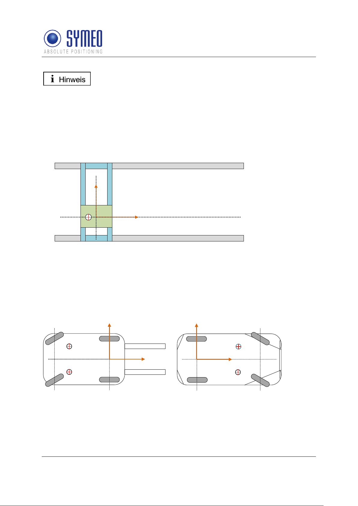
Reference system crane
y
x
(0,0)
center of antenna
reference system forklift
y
x
center of antenna
center of antenna
(0,0)
rear axle front axle
reference system automobile
y
x
center of antenna
center of antenna
(0,0)
front axle
rear axle
LPR®-2DB
Product Documentation
3.3.1 Hover-Track
The HoverTrack model is used for vehicles that can move in x- and y-direction but cannot
turn over its center. A typical example is the trolley of a crane. The name based on a
hovercraft which can move forward and backward as well as sideward.
To make a 2D-positioning the mobile unit needs at least one antenna. The usage of a
second, third or fourth antenna results in more robust and more reliable position.
Figure 5 – HoverCraft model for a trolley
3.3.2 Vehicle-Track
If the object can also turn around its center the vehicle-track model is used. Examples for the
vehicle model are each kind of steerable vehicles (fork lift, van carrier, automobile, etc.). It is
possible to determine besides the 2D position also the orientation of the vehicle. For this it is
at least a second antenna necessary.
Figure 6 – Vehicle Model for a forklift and a trolley
3.4 System Design
Each LPR unit (base station, integral station) contains a DSP. For each LPR unit a
configuration file is provided by SYMEO.
Copyright © Symeo 2012
Page 23 of 132
System Description

Symeo LPR®-System
LPR-2DB Station (Mobile
unit):
basestation_config.txt
LPR-2DB Integral Station
(Fixed-mounted unit /
transponder):
stationXX0_config.txt
stationXX1_config.txt
stationXX2_config.txt
stationXX3_config.txt
stationXX4_config.txt
stationXX5_config.txt (XX: Cell-ID)
Master LPR-2DB Integral
Station (Fixed-mounted
master unit /master
transponder):
stationxxM_config.txt (XX: Cell-ID)
DSP
LPR-2DB
Integral Station/
Transponder
DSP
Master LPR2DB Integral
Station/ Master
Mobile unit/ base station
ARM9
DSP
RS232
User
RS232 Service
TCP/IP
User & Service
RS232
User & Service
access via radio
channel (FSK channel)
access via
TCP/IP or
serial interface
access via radio
channel (FSK channel)
LPR®-2DB
Product Documentation
The configuration files are:
The settings for the files are described in chapter 7.2.
The access to the LPR-2DB Station can either be done via TCP/IP or via RS232 interface.
The LPR-2DB Integral Station and the master LPR-2DB Integral Station can only be
accessed via the frequency channel of the mobile station.
Figure 7 – LPR units including DSP: Access to the DSP via TCP/IP, RS232 or frequency
channel
In chapter 7.3 all different connections to the LPR stations are described. To configure the
connection via TCP/IP web interface exists (chapter 0).
3.4.1 2D Positioning
Each mobile unit calculates the distance of its antennas to each LPR-2DB Integral Station/
transponder. A positioning does not happen in this moment, only the calculation of 6 single
1D distance measurements.
Copyright © Symeo 2012
Page 24 of 132
System Description

Symeo LPR®-System
DSP
ARM9 (SW
FusionEngine)
PC (SW
FusionEngine)
RS232
RS
232
(optional: Netcat)
PC (SW
Symeo Map)
PC (SW
Symeo Map)
Mobile Einheit
TCP/IP
RS
232
TCP/IP
In mode 1 (Basic Cell) and in mode 2a (Managed Cell) the cell
coordinates of the transponders are stored in the Fusion Engine. In
mode 2b (Managed Cell) and mode 3 (TDOA) the coordinates of the
transponders are stored in the cell master.
LPR®-2DB
Product Documentation
These 1D distances are forwarded to the software FusionEngine. The FusionEngine can
either be on the ARM9 board of the mobile unit or on a separate PC of the customer. In the
software FusionEngine all 1D distance measurement are merged to a 2D positioning.
Figure 8 – cycle of a 2D positioning measurement and possible interfaces
Furthermore in the files for the FusionEngine are set the parameters of the model (see
chapter 3.3) as well as the settings for the antennas (coordinates, calibration).
The position calculated in the FusionEngine can be graphical shown with the software
Symeo MAP (see chapter 0).
Copyright © Symeo 2012
Page 25 of 132
System Description

Symeo LPR®-System
All corresponding installation, repair and servicing work must be carried
out by qualified and trained technicians.
Technical Data
Power draw
RS232 port, 4 W
TCP/IP port, 6 W
Voltage range
10-36VDC
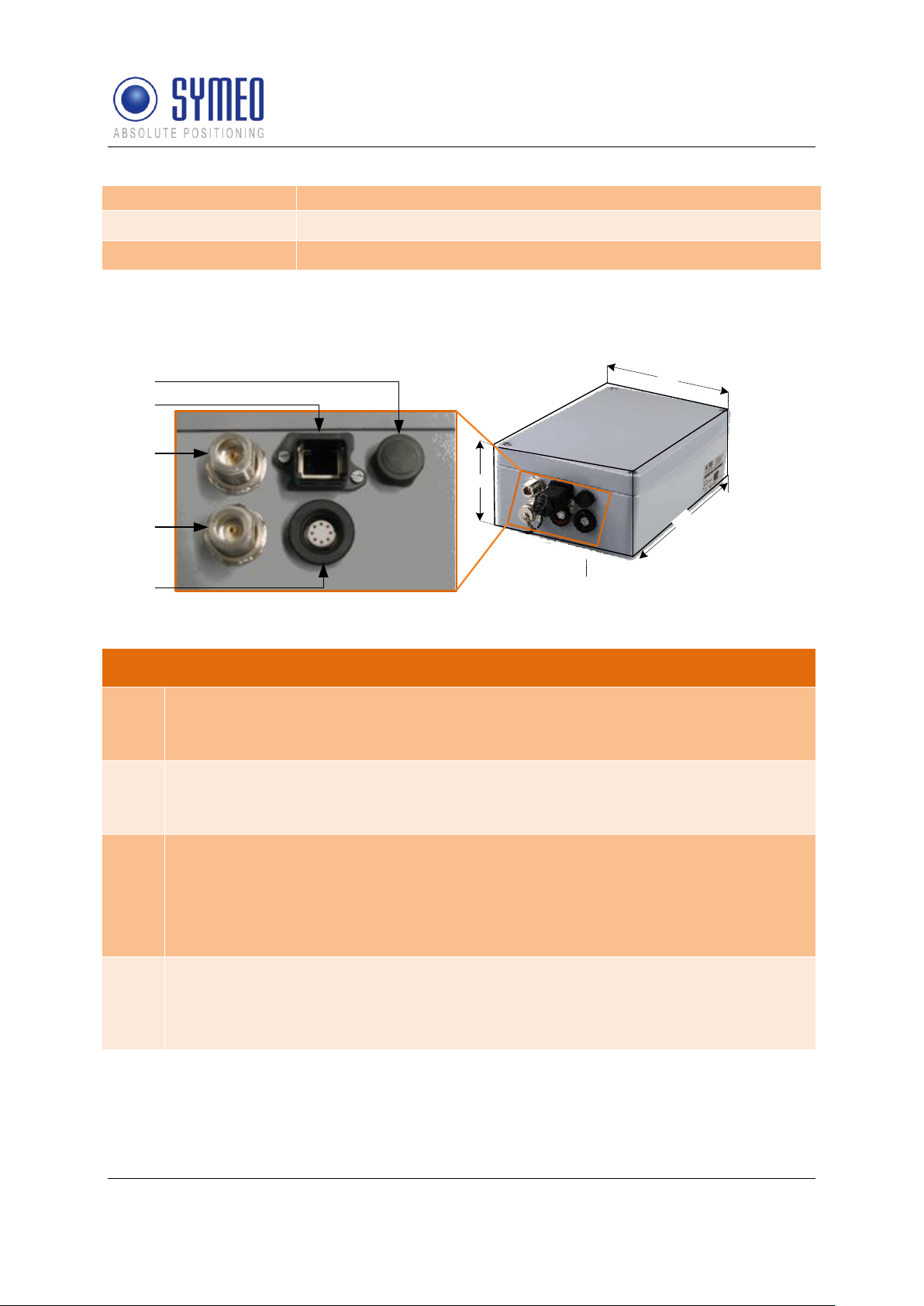
Dimensions (LxWxH)
260 x 160 x 91 mm
Type of protection
IP 65 with appropriate cable connectors
Connections
Power-Supply and Communication: Plugged connection
Antenna: Screwed cable gland
LPR®-2DB
Product Documentation
4 Hardware
4.1 System components – Overview
The system can exist of multiple cells and mobile units for the vehicles. Each cell exists of 4
to 6 LPR transponder stations (type integral). Depending on the chosen operating mode a
master is added to each cell. The 4 to 6 LPR-2DB Integral Stations/ Transponders as well as
the master LPR-2DB Integral Station/ maser transponder is mounted at a fixed place, e.g. a
wall or light poles. On the mobile units LPR stations (type: compact, BSB000313,
BSB000319, BSB000603, BSB000604, BSB000605, BSB000606) are installed.
Additional hardware for the mobile units are connector boxes, connector cables and
antennas.
For the determination of the position of the LPR-2DB Integral Station at the light poles or at
the wall the system range of max. 300 meters and the position of the antennas on the
vehicles are important.
4.2 LPR-2DB Station (mobile station)
4.2.1 Overview compact station
Following hardware exists for an LPR station on the mobile unit:
BSB000313 (single receiver, TCP/IP interface, 2 antenna ports)
BSB000319 (single receiver, RS232 interface, 2 antenna ports)
BSB000603 (double receiver, TCP/IP interface, 4 antenna ports)
BSB000604 (double receiver, RS232 interface, 4 antenna ports)
BSB000605 (double receiver, TCP/IP interface, 2 antenna ports)
BSB000606 (double receiver, RS232 interface, 2 antenna ports)
4.2.2 Technical data compact station
Hardware
Copyright © Symeo 2012
Page 26 of 132
Symeo LPR®-System
Ethernet: Plugged connection
Antennas
Connection of up to 4 independent antennas
Compliance
CE mark
1
91
260
160
2
3
4
5
Description of Interfaces
1
Pressure equalization membrane.
The membrane prevents forming of condensation water inside the Compact Station.
The pressure equalization membrane must not be changed or covered!
2
Network (optional).
The standard industrial Ethernet port of the station is designed as a Harting type
push pull connector.
3, 4
Antenna connections.
The antennas are connected to the Compact Station via a specially converted low-
loss HF cable with N-plug.
3: Antenna port no. 1,
4: Antenna port no. 2.
5
Power supply with integrated communication ports.
Power is supplied via a Lumberg Type 0233 08 push pull connector. There is no
power switch because of the intended area of application. A 3 Ampere (slow blow)
fuse is mounted inside the Compact Station.
LPR®-2DB
Product Documentation
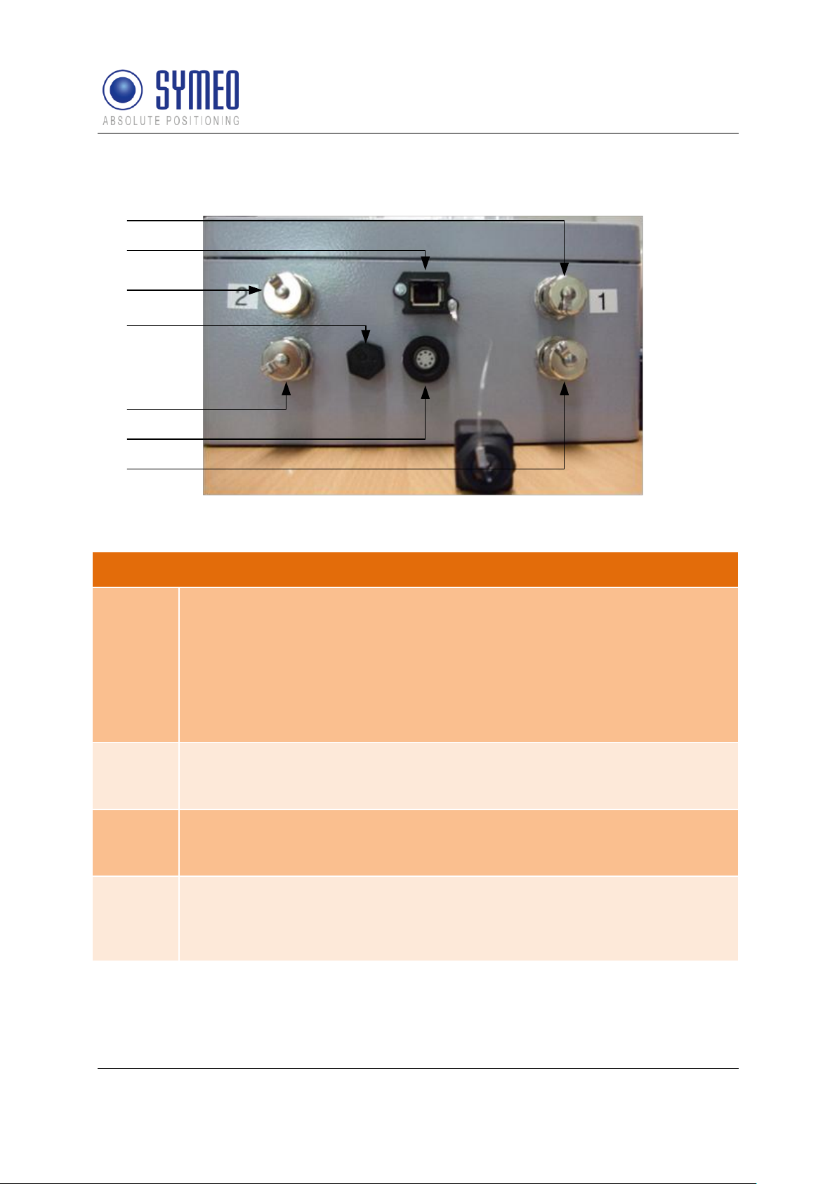
4.2.3 Station BSB000313, BSB000319
Figure 9- interfaces of LPR station on vehicle as a single receiver
Copyright © Symeo 2012
Page 27 of 132
Hardware
Symeo LPR®-System
1
2
3
4
5
6
7
Technical Data and Description of Interfaces
1, 3, 5, 7
Antenna connections.
The antennas are connected to the Compact Station via a specially converted
low-loss HF cable with N-plug.
1: Antenna port no. 1,
3: Antenna port no. 2,
5: Antenna port no. 4,
7: Antenna port no. 3,
2
Network (optional).
The standard industrial Ethernet port of the station is designed as a Harting
type push pull connector.
4
Pressure equalization membrane.
The membrane prevents forming of condensation water inside the Compact
Station. The pressure equalization membrane must not be changed or covered!
6
Power supply with integrated communication ports.
Power is supplied via a Lumberg Type 0233 08 push pull connector. There is
no power switch because of the intended area of application. A 3 Ampere (slow
blow) fuse is mounted inside the Compact Station.
LPR®-2DB
Product Documentation
4.2.4 Station BSB000603, BSB000604, BSB000605, BSB000606
Figure 10 - interfaces of LPR station on a vehicle as double receiver
Copyright © Symeo 2012
Page 28 of 132
Hardware
Symeo LPR®-System
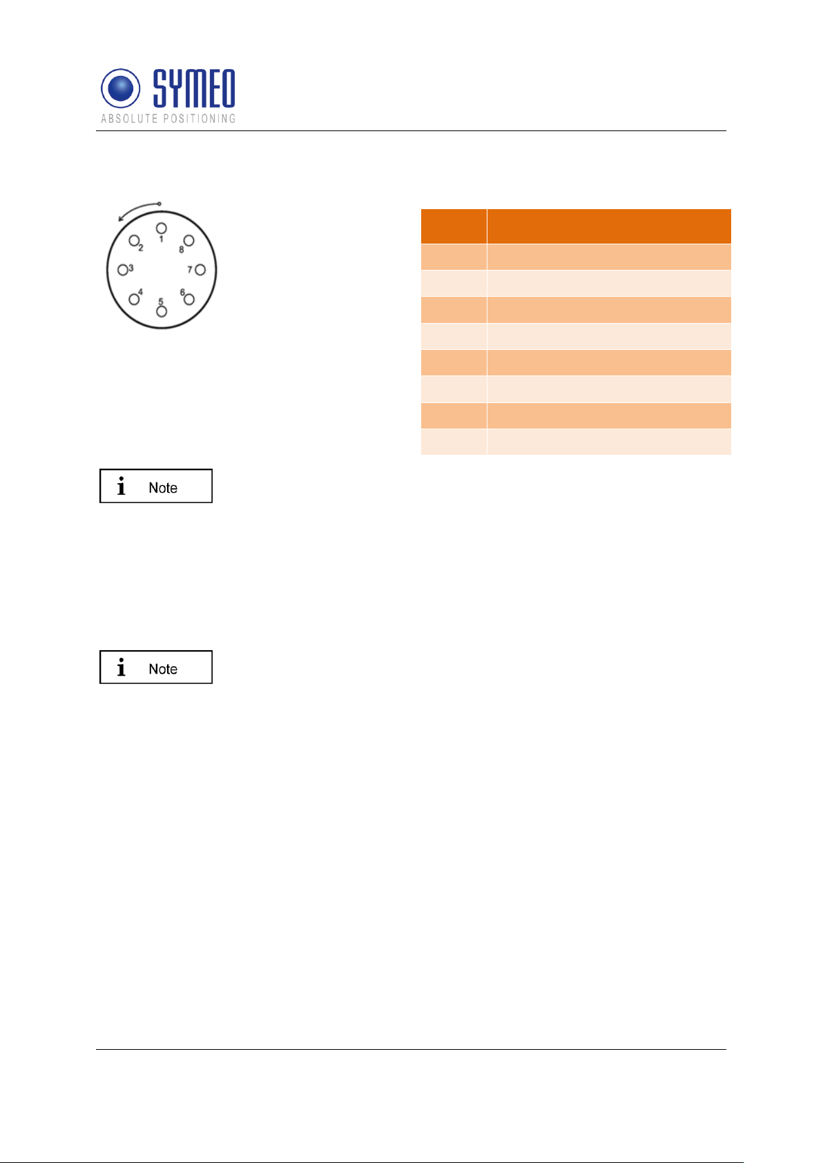
For configuration of the connector with cables, you have to identify the
matching pin assignment on the solder side.
The connectors have an anti twist device.
Option 1: It is possible to order cables (length: 5 m) by Symeo with
integrated Lumberg connector and cut cable head (see chapter 4.3).
Option 2: It is possible to order a connector box to wire all cables (see
chapter 4.3.2).
When plugging the push pull connectors into their sockets check that
the plug doesn’t slip out of the socket when pulling slightly at the cable.
Pin
Function
1
UBB (+)
2
UBB (-)
3
LPR data port RXD
4
LPR data port TXD
5
Network diagnostic port RXD
6
Network diagnostic port TXD
7
GND-RS232
8
GND RS232
LPR®-2DB
Product Documentation
4.2.5 Lumberg Connector Type 0233 08
Figure 11 - Solder side view of the pin
assignment of the Lumberg power connector
plug (power supply with integrated service
port)
4.3 Cables for Compact Station
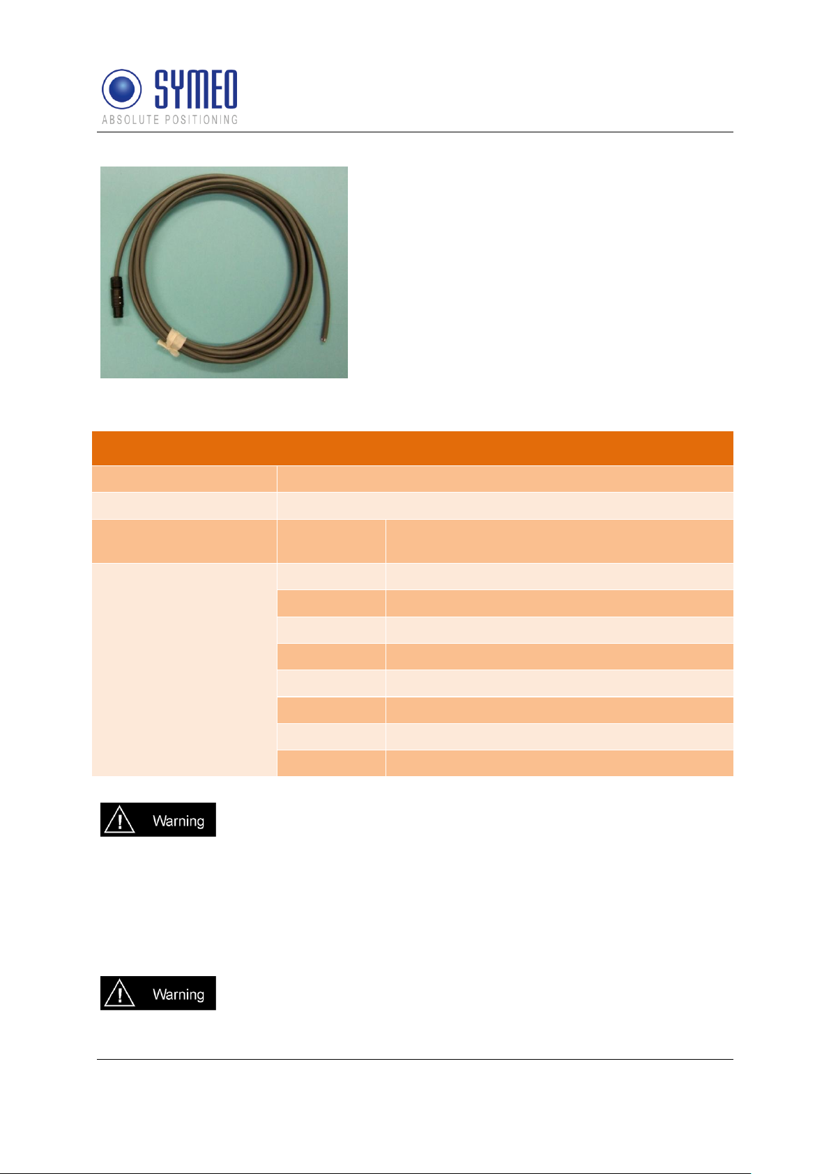
4.3.1 Cable for Power Supply
Cables are delivered with a cable length of 5m and can be cut to the required length.
Copyright © Symeo 2012
Page 29 of 132
Hardware
Symeo LPR®-System
PIN-Assignment of Cable Lumberg Connector 0223 08
Plug
Lumberg 0223 08
Cable
8-wire AWG24 UL/CSA; cladding diameter = 6.4mm
Color according to DIN
47100)
Pin / color
Function
1 – white
UBB (+)
2 – brown
UBB (-)
3 – green
LPR Dataport RXD
4 – yellow
LPR Dataport TXD
5 – grey
Network diagnostics port RXD
6 – pink
Network diagnostics port TXD
7 – blue
GND-RS232
8 – red
GND-RS232 and shielding
Consider the dependency of the maximum baud rate according to the
cable length:
15m: 19.200baud
5m: 57.600baud
<2m: 115.200baud
If this cable is only used for power supply, the TXD-wires of the cable
must be terminated. Otherwise signals from other systems can disturb
the system via the TXD-wire. Then measurements can fail. You have to
LPR®-2DB
Product Documentation
Figure 12 – Cable for power supply with integrated RS232 interface
According to the cable length the baud rate at the stations has to be adjusted.
Copyright © Symeo 2012
Page 30 of 132
Hardware

Symeo LPR®-System
ground the TXD-wires (PIN 4 and PIN 6) with PIN 7 and 8.
Technical Data: HARTING Push Pull Connector
Wire gauge data
AWG 22 – 24 stranded
AWG 22 – 23 solid
Wire isolation
Max. 1.6 mm Ø
Cable diameter
6.5 mm – 7.2 mm
Figure 13 – Connector box
Connection Box
Size (LxWxH)
125mm x 80mm x 57mm (without cable bushing)
Position mounting holes
4 x diameter 4.3mm; 52 x 113mm
Clamps
Wago 870-911 for cable diameter 0.08 till 2,5mm² ( till 4mm² if
flexible cables)
LPR®-2DB
Product Documentation
4.3.2 Recommended Cable Types HARTING Push Pull Connector
If the station is delivered with a HARTING Push Pull connector following type of cable should
be considered for assembling:
HARTING RJ Industrial® Ethernet Shielded Twisted Pair Standard Cable, AWG 22 solid,
according Category 5 cabling standard (ISO/IEC 11801:2002)
HARTING RJ Industrial® Ethernet Shielded Twisted Pair Trailing Cable, AWG 22/7
stranded, according Category 5 cabling standard (ISO/IEC 11801:2002)
Transmission characteristics according Category 5 ISO/IEC 801:2002 and EN 50173-1:
The assembly instruction of the HARTING Push Pull Connector is delivered with the product.
4.4 Connector box
The connection box is configured with 14 clamps. Therefore the connector box can be used
either for power supply or for relays.
Hardware
Copyright © Symeo 2012
Page 31 of 132

Symeo LPR®-System
Cable bushing
3 x PG Connection for cladding diameter 5 – 10 mm
1 x sealing cap
Protection category
IP65
If usage of appropriate cables (diameter 5 till 8mm) and correct
connection of cap and cable bushing is assured
If the cable bushing are not used the sealing cap (including the sealing
ring) has to be mounted to keep the protection category IP65.
Figure 14
1: Power consumption (by
customer)
2: Serial Interface (by customer)
3: From LPR
The shielding has to be allocated.
3 2 1
LPR®-2DB
Product Documentation
4.4.1 Example: Connector Box
Connection of an 8-pin cable
In this example the power supply is at pin1 and 2. The serial interface is at pin 5 to 10 and
the shielding at pin 14.
For safety of clamping use appropriate wires end sleeves according to AWG24.
If this cable is only used for power supply, the TXD-wires of the cable must be terminated.
Otherwise signals from other systems can disturb the system via the TXD-wire. Then
measurements can fail. You have to ground the TXD-wires (PIN 4 and PIN 6) with PIN 7 and
8.
Hardware
Copyright © Symeo 2012
Page 32 of 132

Symeo LPR®-System
The electronics inside LPR-2DB Integral Station hood itself do not
include any components that can be serviced by the user. They must
not be detached from the hood because they contain parts that are
electrically charged inside when connected to the LPR-2DB Integral
Station base.
All corresponding installation, repair and servicing work must be carried
out by qualified and trained technicians.
If the LPR-2DB Integral Station is installed on a pole, it must be secured
to ensure that it does not slip.
If the direct current is incorrectly connected, the LPR-2DB Integral
Station will be damaged and must be returned to the SYMEO service for
further inspection.
The plugged connection between the LPR-2DB Integral Station hood
and base provides protection against direct contact, i.e. it can be
connected and disconnected while it is under load.
Refer to the general design notes regarding your LPR system.
Technical Data
Power draw
4W, 10-36VDC
Dimensions (LxWxH)
212 (incl. mounting bracket) x 126 x 281 mm
Type of protection
IP 65 with feasible cables according to the cable gland
Antenna
Integrated inside the housing
Compliance
CE mark
LPR®-2DB
Product Documentation
4.5 LPR-2DB Integral Station (fixed mounted unit)
Following hardware exists for an LPR-2DB Integral Station on the light poles:
TPB000250 (LPR-2DB Integral)
TPB000251 (LPR-2DB Integral)
TPB000530 (LPR-2DB Integral, cell coordinator)
4.5.1 Technical Data: LPR-2DB Integral Station
Copyright © Symeo 2012
Page 33 of 132
Hardware

Symeo LPR®-System
7
5 6 4
3 2 1
Figure 15 – Hood, Base and Bracket (from left to right)
1
LED
2
Cable feedthrough
3
Terminal pin
4
Terminal block
5
Plug
6
Transponder locating
slot
7
Installation points
LPR®-2DB
Product Documentation
4.5.2 Components of LPR-2DB Integral Station
The base is where the terminal block for the electrical connection and the plug for connecting
the hood is located.
Strain relief clamps are applied to the base to avoid mechanical stress on the power supply
cables.
The LPR-2DB Integral Station can be fixed onto the mounting bracket with the two screws
provided with the base.
Depending on the requirements and application, the LPR-2DB Integral Station can be
adjusted vertical with an angle from 0° to 25°.
4.6 LPR Antennas for Compact Station (mobile unit)
There are different antennas that can be installed depending on the required directional
characteristic.
Copyright © Symeo 2012
Page 34 of 132
Hardware

Symeo LPR®-System
6 dBi Omnidirectional Antenna
10 dBi Omnidirectional Antenna
8,5°
vertical
-3 dB
0 dB
-3 dB
30°
vertical
-3 dB
0 dB
-3 dB
A
A
A = 190mm
d = 20mm
A = 440mm
d = 20mm
Antenna Connector Type N
Antenna Connector Type N
10 dBi Sector Antenna
vertical
60°
30°
(optional)
-3 dB
0 dB
-3 dB
horizontal
160°
-3 dB
0 dB
-3 dB
A
d
B
A = 280mm
B = 125mm
d = 150mm
Antenna Connector Type N
The LPR-2DB integral station contains an integrated 10 dBi antenna.
Only this integrated antenna is approved to be in compliance with part
15 of FCC rules and with RSS-210 of Industry Canada.
LPR®-2DB
Product Documentation
Figure 16- Typical LPR antennas for 2D applications
4.6.1 Mounting devices of LPR Antennas
Depending on the required antenna, different adapters are available
Hardware
Copyright © Symeo 2012
Page 35 of 132

Symeo LPR®-System
6 dBi and 10 dBi Omnidirectional Antenna
A
A = 228mm
B = 38mm
d = 50mm
B
d
applicable for wall and pole mounting
10 dBi Sector Antenna
A
d
B
A = 150mm
B = 128mm
d = 100mm
applicable for wall and pole mounting
LPR®-2DB
Product Documentation
Figure 17 - Available Adapters for different Antenna Types
Copyright © Symeo 2012
Hardware
Page 36 of 132

Symeo LPR®-System
During Installation, the LPR-2DB Station has to be opened. Therefore it
is important to avoid ingress of moisture, dust or any particles into the
housing during the installation process. Make sure that there is enough
room for the connectors, and particularly that the antenna cable is
accessible; pay attention to the permitted bending radius (center of
radius to cable core) for standard cables of 10,5cm (for multiple bending
under mechanical load) and 4cm (unloaded and static bending).
The LPR-2DB Station should preferably be installed so that the
connecting sockets point downwards. In this way, the connections are
protected from rain and dust.
To install the LPR-2DB Station, you require 4 round head M6 x 30
screws (at least).
LPR®-2DB
Product Documentation
5 Installation
5.1 Installation of the LPR-2DB Station (mobile unit)
BSB000313 (single receiver, TCP/IP interface, 2 antenna ports)
BSB000319 (single receiver, RS232 interface, 2 antenna ports)
BSB000603 (double receiver, TCP/IP interface, 4 antenna ports)
BSB000604 (double receiver, RS232 interface, 4 antenna ports)
BSB000605 (double receiver, TCP/IP interface, 2 antenna ports)
BSB000606 (double receiver, RS232 interface, 2 antenna ports)
Check the position of the station on the device on which the LPR-2DB Station is to be
installed (e.g. a crane bridge). Bear in mind the installation instructions listed above.
Drill holes in the device on which the LPR-2DB Station/ Rubber pads are to be installed.
Drill-hole distances: 11 cm wide, 24 cm high.
Rubber pads are provided by Symeo (see Figure 18). The rubber pads reduce vibration
to the LPR station. Place 4 rubber pad into the drill holes ad fasten the screws.
Open the LPR-2DB Station: With a Phillips screwdriver (Size 0), loosen the top four
screws of the LPR-2DB Station lid.
Screw the LPR-2DB Station tightly to the device. The installation holes of the rubber pads
are provided for this purpose. Check that the station is mounted securely.
Close the station: Place the cover of the LPR-2DB Station on top and fasten the cover
with the four screws. Make sure that the cover is securely attached to the housing.
Copyright © Symeo 2012
Page 37 of 132
Installation

Symeo LPR®-System
All installation, repair and servicing work must be carried out by qualified
and trained electrical technicians!
Polarity reversal or incorrect connection will damage the Integral
Station. If this happens, the LPR-2DB Integral Station must be returned
to the SYMEO service for inspection.
LPR®-2DB
Product Documentation
Figure 18 – Rubber pad for Compact station
5.2 Installation of the LPR-2DB Integral Station
TPB000250 (LPR-2DB Integral)
TPB000251 (LPR-2DB Integral)
TPB000530 (LPR-2DB Integral, cell coordinator)
5.2.1 Electrical Interface
The bases can be connected via the terminal block.
Installation
Copyright © Symeo 2012
Page 38 of 132

Symeo LPR®-System
LPR®-2DB
Product Documentation
Figure 19 – Connecting the power supply
5.2.2 Installation
The LPR-2DB Integral Stations are supplied already preassembled (hood + base) and with
the bracket separate. Figure 20 shows various views of the assembled LPR-2DB Integral
Station including the mounting bracket.
Installation
Copyright © Symeo 2012
Page 39 of 132

Symeo LPR®-System
LPR®-2DB
Product Documentation
Figure 20 – Complete LPR-2DB Integral Station including mounting bracket
The bracket can be bolted directly to the wall. The LPR-2DB Integral Station can also be
secured to posts/poles with two pipe clips (not included).
Mount the bracket on the wall or a pole.
Detach the hood from the base with the Torx-head screwdriver T25.
Insert the cable through the feedthrough.
Fit the LPR-2DB Integral Station base onto the bracket and tighten it with an SW13 fork
wrench.
Pass the cable through the terminal pins to the terminal block and clamp it according to
the instructions on the terminal block.
Tighten the screwed cable gland on the feedthroughs with an SW 19 fork wrench.
Fit the LPR-2DB Integral Station hood (note the assignment of 90°/160° in the installation
plan).
Screw the LPR-2DB Integral Station hood tightly onto the base.
You can use the slots in the LPR-2DB Integral Station bracket to adjust the vertical
orientation of the LPR-2DB Integral Station between 0° and 25° (mandatory if so
indicated in the installation plan). Tilt the LPR-2DB Integral Station to the required angle
("View" on the antenna of the base station) and tighten the screws with an SW 13 fork
wrench.
Installation
Copyright © Symeo 2012
Page 40 of 132

Symeo LPR®-System
(0,0,0)
x
y
Short-ID: 101
Short-ID: 10M
Short-ID: 102
Short-ID: 103
Short-ID: 104
Short-ID: 100
Short-ID: 105
Figure 21 – Example Cell plan for one cell
LPR-2DB Integral Station
Installation
Cell
ID
Angle
Pole
10 0 -143
LT-11
10 1 -90
LT-08
10 2 -41
LT-05
10 3 0
LT-06
10 4 180
LT-09
10 5 -180
LT-12
10 M -40
LT-05
Table 1 – Example of light pole
allocation table
If several antennas are used, ensure that they are connected to the
correct ports.
When installing the cable, ensure that electrostatic charging does not
occur.
Make sure that the cable is not kinked or trapped during installation. The
minimum bending radius must always be maintained. With the standard
antenna cables delivered, the minimum bending radius (center of radius
to cable core) for standard cables is 10,5cm (for multiple bending under
mechanical load) and 4cm (unloaded and static bending). The cable
must not be attached in a way that alters its cross-section. On demand,
cables with different flexibility characteristics are available.
The antenna plug must not be removed (e.g. for installation purposes)
or repaired because the specified electrical properties can only be
achieved with mechanical installation assistance.
When installing the antenna cable, ensure that the screw connection is
seated properly. The antenna cable plugs should be finger-tightened
before tightening with an appropriate tool to no more than 1.3 Nm
LPR®-2DB
Product Documentation
5.2.3 Allocation of LPR-2DB Integral Stations and Installation Points
If a cell plan and/or a light pole allocation table is drawn by Symeo or together with Symeo,
the position and orientation of the LPR-2DB Integral Station must be installed referred to this
master document. The cell plan contains the LPR-2DB Integral Stations with a definite
identifier installed at the wall or on the light poles (compare chapter 7.1.1).
5.3 Installation of LPR antennas
5.3.1 Connection of antenna cables to the mobile units (LPR-2DB Station)
Installation
Copyright © Symeo 2012
Page 41 of 132

Symeo LPR®-System
tightening torque.
The line of sight between the antennas on each unit must not be
obstructed. Therefore, when installing the antenna fixture, ensure that
no components are blocking the line of sight between the antennas. If
necessary, contact the SYMEO technical department.
If you change the position of one antenna, this will affect the
measurement data that is output.
LPR®-2DB
Product Documentation
5.3.2 Mounting of LPR antennas
Install the antenna fixture according to the accompanying operating instructions.
Secure the antenna in the fixture.
Connect the antenna to the antenna cable.
Copyright © Symeo 2012
Page 42 of 132
Installation

Symeo LPR®-System
4 slots for
clamping
Assembly bracket
of antenna
Fixing nut for
antenna
LPR®-2DB
Product Documentation
Figure 22 – Antenna with assembly bracket and antenna cable
5.3.3 Notes for mounting position of LPR antennas on the mobile unit
Considering the correct mounting position of the antennas you have to take care to
guarantee a free line of sight between the antenna(s) on the vehicle and all LPR-2DB
Integral Stations.
If construction on the vehicle partly interfere the free line of sight (e.g. driver cabin), the
distance between the antennas and this construction barrier should be chosen big to make
the “blind” sector small.
Copyright © Symeo 2012
Page 43 of 132
Installation

Symeo LPR®-System
1
3
2
Antenna
Antenna
1
Free visual range of antennas
2
Construction (e.g. driver cabin)
3
„blind“ sector
Antenna
Antenna
Center of rotation of
vehicle
Center of rotation of
vehicle
LPR®-2DB
Product Documentation
Figure 23– Mounting position of antenna
On the other hand the antenna should be close to the center of rotation of the vehicle type to
make the positioning error due to the rotation of the vehicle as small as possible (see Figure
24).
The position of the antenna(s) is in some cases a trade-off between minimizing the error due
to construction barrier on the vehicle and the minimizing the rotation error. Contact Symeo if
there are questions regarding the installation position of the antenna.
If a second antenna is used on the vehicle the distance to the first antenna should be at least
1 meter to calculate an orientation of the vehicle. The orientation is necessary to determine a
load position if the antenna is not mounted above the load position.
Figure 24 – Mounting position of antenna
Depending on the position of the LPR-2DB Integral Stations different minimum system
ranges result. The system range depends on the selection of the antennas and the antenna
cable length as well as of the antenna cable length. In general the antenna cable length on
the vehicle should be as short as possible to minimize the signal loss in the cable.
Copyright © Symeo 2012
Page 44 of 132
Installation

Symeo LPR®-System
LPR®-2DB
Product Documentation
Installation
Copyright © Symeo 2012
Page 45 of 132

Symeo LPR®-System
LPR®-2DB
Product Documentation
6 Coordinate System
The LPR-2DB Integral Station and the antennas of the mobile stations must be surveyed.
6.1 Survey Instructions for the LPR-2DB Integral Station
The Integral Stations are supplied already preassembled (hood + base) and with the bracket
separate. Figure 25 shows various views of the assembled LPR-2DB Integral Station
including the mounting bracket
Figure 25 – Complete LPR-2DB Integral Station including mounting bracket
6.1.1 Coordinate system of LPR-2DB Integral Station
The accuracy of the position output depends in large part on the exact recording of the
positions of the LPR-2DB Integral Station. Accordingly, the positions of the installed stations
must be calibrated to a tolerance of +/- 2 cm (in each direction). At the same time, the
orientation of each Integral Station in the x-y direction is also recorded. The inclination of the
stations is not recorded.
LPR works with a Cartesian coordinate system, which is spanned by the x-y plane (see
Figure 9). The positions of the Integral Stations are identified in this coordinate system. By
default, the coordinate system has a positive effective direction.
Coordinate System
Copyright © Symeo 2012
Page 46 of 132

Symeo LPR®-System
z
y
x
[0,0,0]
Measurement point
LPR®-2DB
Product Documentation
Figure 26 – transponder coordinate system
Positions in all four quadrants can be measured in the transponder coordinate system: LPR
calculates the 2D position in the plane spanned by x and y.
Since it is not always possible to mount all the LPR components (LPR-2DB Integral Station,
LPR-2DB Station antennas) in this plane, the deviation of the installation position in "z"
relative to this plane must be specified for all LPR components.
In plane areas the z-position can be estimated directly towards the ground level.
The LPR-2DB Integral Stations must be measured in x-/y- and z-direction.
6.1.2 Reference point of LPR-2DB Integral Station
The position of the measuring point is critical for measuring the LPR-2DB Integral Station.
The measuring point is marked by matting on the stations housing.
In a top view, the measuring point is located at the same level as the antenna patches
(horizontal structures, roughly in the middle of the board portion above the copper reflector).
In the front view, the zero point is located midway between the copper reflectors.
Figure 27 – Position of the measuring point on the LPR-2DB Integral Station
Copyright © Symeo 2012
Page 47 of 132
Coordinate System

Symeo LPR®-System
LPR®-2DB
Product Documentation
Figure 28 – Position of the measuring point on the Integral Station
6.1.3 Orientation of LPR-2DB Integral Station
The alignment of the stations is recorded as a vector in the coordinate system that is defined
for the application, and is entered as an ex/ey value. Integer values are possible for ex/ey.
The following diagram illustrates this principle (corresponding negative values for an opposite
alignment).
Figure 29 – Examples of LPR-2DB Integral Station alignment with ex/ey value
Coordinate System
Copyright © Symeo 2012
Page 48 of 132

Symeo LPR®-System
a
y
x
Description
Meaning
Cell
Cell number
ID
LPR-2DB Integral Station ID
TID
Fixed allocated
x
x-position of the transponder in own coordinates in mm
Short ID
LPR-2DB Integral Station formatting
Cell
ID
TID
x , y , height
,
direction
x (ex)
,
direction
y (ey)
,
beam
width
12 0 T0=(
, , , , , 200
)
12 1 T1=(
, , , , , 200
)
12 2 T2=(
, , , , , 200
)
12 3 T3=(
, , , , , 200
)
12 4 T4=(
, , , , , 200
)
12 5 T5=(
, , , , , 200
)
12 M T30=(
, , , , , 200
)
LPR®-2DB
Product Documentation
It is also possible to compute the orientation vectors from the angle of the integral station in
the plane:
Figure 30 – Computation of ex/yx from angle a
Hereby is ex = cos(a) and ey = sin(a).
So just compute the values and multiplicate with 10 and truncate the decimal place:
Example: a = 12°, 10*cos(a)=9,78; 10*sin(a)=2,08 ex = 9; y = 2
6.1.4 Formatting of coordinates
The coordinates of the integral stations must be provided as EXCEL-file in following format:
Coordinate System
Copyright © Symeo 2012
Page 49 of 132

Symeo LPR®-System
y
y-position of the transponder in own coordinates in mm
height
Height of transponders above ground in mm
direction x
x-component of orientation vector of transponder in own
coordinates
direction y
y-component of orientation vector of transponder in own
coordinates
beam width
Horizontal opening angle of transponder
Center of antenna 0
Center of antenna 1
Center of rotation of vehicle
Reference system forklift
x
y
Center of antenna 3
Center of antenna 2
Steering axis Fixed axis
Center of load position
LPR®-2DB
Product Documentation
6.2 Surveying of LPR-2DB Compact Station on mobile unit
The position of the antennas must be surveyed in the coordinate system of the vehicle. The
origin of the coordinate system for the vehicle depends on the vehicle type.
6.2.1 Reference system for vehicle type: forklift
The origin of the reference system for the forklift is on the front axle. The x-axis shows in
positive driving direction. Referring to this origin the antennas and the load position must be
surveyed. The coordinates of the rotation point are in the middle of the fixed axis for a fork
lift.
Figure 31 – reference coordinate system and installation position of antennas on a forklift
The z-direction shows the height of the antennas related to the ground (compare chapter
surveying of antennas).
6.2.2 Reference system for vehicle type: Van Carrier
The origin of the reference system for the van carrier is on the rotation point of the vehicle.
The x-axis shows in positive driving direction. The coordinates of the rotation are identical to
the load position. Therefore the coordinates for the load position can be set to zero.
Copyright © Symeo 2012
Page 50 of 132
Coordinate System

Symeo LPR®-System
Center of antenna 0
Center of antenna 0
Center of rotation of vehicle
= center of load position
Reference
system VC
x
y
Center of antenna 3
Center of antenna 2
Center of antenna 0
Center of antenna 1
Center of orientation of vehicle
reference system:
automobile
x
y
Center of antenna 3
Center of antenna 2
Steering axisFixed axis
Load position
LPR®-2DB
Product Documentation
The z-direction shows the height of the antennas related to the ground (compare chapter
surveying of antennas).
Figure 32 - reference coordinate system and installation position of antennas on a van-carrier
6.2.3 Reference system for vehicle type: passenger car
The origin of the reference system for the automobile is on the rear axle. The x-axis shows in
positive driving direction. Referring to this origin the antennas and the load position must be
surveyed. The coordinates of the rotation point are in the middle of the fixed axis for an
automobile.
Figure 33 – reference coordinate system and installation position of antennas on an
automobile
Copyright © Symeo 2012
Page 51 of 132
Coordinate System

Symeo LPR®-System
Reference system crane
y
x
(0,0,0)
Center of antenna
x
y
LPR®-2DB
Product Documentation
The z-direction shows the height of the antennas related to the ground (compare chapter
surveying of antennas).
6.2.4 Reference system for vehicle type: crane/ trolley
Figure 34 – reference coordinate system and installation position of antennas on a crane
The origin of the reference system for the crane can be chosen anywhere, because there is
no rotation. The x-axis shows in positive driving direction.
The z-direction shows the height of the antennas related to the ground (compare chapter
surveying of antennas).
6.3 Surveying of LPR antennas
Copyright © Symeo 2012
Page 52 of 132
Coordinate System

Symeo LPR®-System
Antenna
measurement point
Antenna position
Port
x y Height
(0)
2.576
3.456
12.300
(1)
1.000
2.876
12.345
(2)
-2.123
-1.200
12.816
(3)
3.378
4.503
12.461
Load position
[Load Position]
Description
Meaning
LPR®-2DB
Product Documentation
Figure 35 – measurement point of antenna
The reference point of the antenna for surveying is in the middle of rotational solid of the
antenna.
6.3.1 Formatting of coordinates
The position of the antennas must be provided to Symeo in the following EXCEL format
(compare Table 2 ).
The following values must be entered into the file by the surveyor:
Antenna position:
Table 2 – Antenna position
Copyright © Symeo 2012
Page 53 of 132
Coordinate System

Symeo LPR®-System
Port
Antenna port of the connected antenna. (0) means antenna
port 1, (1) means antenna port (2) etc.
x
x-position of the antenna at the connected port in
coordinates of the vehicle. Specification is in meters and with
3 decimal numbers.
y
y-position of the antenna at the connected port in
coordinates of the vehicle. Specification is in meters and with
3 decimal numbers.
height
Height of the antenna over ground. Specification is in meters
and with 3 decimal numbers.
LoadPosition
Operation point ; e.g. center of spreader (x, y, z)
LPR®-2DB
Product Documentation
Coordinate System
Copyright © Symeo 2012
Page 54 of 132

Symeo LPR®-System
Cell-ID
Station-ID
Short-ID
10 0 100
10 1 101
10 2 102
10 3 103
10 4 104
10 5 105
10
30
10M
The Master LPR-2DB Integral Station always has the station-ID 30. In
the Short-ID the master is indicated with “M”. The Master LPR-2DB
Integral Station is only relevant in the operating mode 2 (Managed Cell)
and 3 (TDOA).
(0,0,0)
x
y
Kurz-ID: 101
Kurz-ID: 10M
Kurz-ID: 102
Kurz-ID: 103
Kurz-ID: 104
Kurz-ID: 100
Kurz-ID: 105
LPR®-2DB
Product Documentation
7 Commissioning
The commissioning part consists of following steps:
Checking of installation
Configuration and upload of files for the DSP to the LPR units
Configuration and upload of files for the FusionEngine
Commissioning the LPR system with Symeo MAP
7.1 Check list installation and surveying
After mechanical and electrical installation the following steps should be succeeded:
7.1.1 Cells, Integral stations
LPR-2DB Integral Station are mounted (position and orientation) like shown in the cell
plan
The three-digit short-ID of each LPR-2DB Integral Station is the same as in the cell plan.
Each LPR-2DB Integral Station has a three-digit short ID, which consist of a two-digit Cell-ID
and a one-digit Station-ID.
Figure 36- Cell plan
Between all fixed mounted stations (LPR-2DB Integral Station) is a free line of sight
The power supply for the LPR-2DB Integral Station is connected. (LPR-2DB Integral
Station flash, Master LPR-2DB Integral Station lightens)
Screwing of external antennas of LPR station (type: compact) is installed correctly.
Copyright © Symeo 2012
Page 55 of 132
Commissioning

Symeo LPR®-System
Figure 37
The folder “mobile units”
contains the parameter for
mobile LPR unit. “Static cells”
contains the parameter for the
fixed mounted LPR station (e.g.
surveyor data). All LPR units are
labeled with their serial number
in the folder structure.
In the mode 1 (Basic Cell) all configuration files for the DSPs are
preconfigured and no changes of the files are allowed. In the mode 2
(Managed cell) and 3 (TDOA) the configuration file of the master
transponder has to be changed as long as no surveyor data was
available to Symeo by delivery.
File
Modification
basestation_config.txt
No modification necessary
stationXXM_config.txt
Input of Transponder coordinates (only mode 2b and 3b)
LPR®-2DB
Product Documentation
7.1.2 LPR-2DB Station (Mobile units)
Antennas have a free line of sight
Screwing of external antennas is correct
Antennas are labeled to allocate them to the right port of the mobile station. This is
necessary for the orientation of the vehicle.
The maximum bending radius of external antenna cables is correct
7.1.3 Formatting of coordinates
Compare the coordinate data from the surveyor with the plan coordinates of the cell plan.
7.1.4 Folders structure
The configuration files for the mobile units and the fixed mounted units are delivered in the
following directory to the customer (compare chapter 2.2):
7.2 Editing of configuration files for the DSP
If changes of a configuration for a DSP are necessary or a replacement unit is used, the
following files must be uploaded and/or modified:
Commissioning
Copyright © Symeo 2012
Page 56 of 132

Symeo LPR®-System
(only Mode 2 and 3 –
master transponder)
No modification necessary for mode 1, 2a and 3a
stationXX#_config.txt
(all transponders)
No modification necessary
The “XX”-sign replaces the Cell number of the master transponders, the
„M“-sign indicates the master station-ID 30. The “XX”-sign replaces the
Cell number of the transponders, the „#“-sign the station-ID.
This file is preconfigured by delivery and needs no changes.
This file for the master transponder only exists in mode 2b (Managed
cell) and mode 3b (TDOA). In mode 1 (Basic cell) the base station(s)
organize(s) the measurements and the master transponder is not be
applied. In 2a and 3a a file XXM_config.txt exists but no changes of this
file should be done.
LPR®-2DB
Product Documentation
7.2.1 File basestation_config.txt
7.2.2 File stationXXM_config.txt
Figure 38 – Entry of transponder coordinates in the file XXM_config.txt (only mode 2b and
3b)
Copyright © Symeo 2012
Page 57 of 132
Commissioning

Symeo LPR®-System
StationID x-coordinate
ycoordinate
zcoordinate
dir_x
(x-direction of
transponder)
dir_y
(y-direction of
transponder)
beam
width
These files is preconfigured by delivery and needs no changes.
Mobile unit (Base station)
Basestation_config.txt
Transponder
StationXX0.txt … stationXX5.txt (XX: Cell-ID)
Master (optionally)
StationXXM.txt (XX: Cell-ID, M: Master)
LPR®-2DB
Product Documentation
Enter the coordinates from the surveyor for each transponder (T0 – T5) and for the master
transponder (T30) into the file for the master transponder. The values are x- , y-, z-direction
and the orientation of all transponders in x- and y-direction (see chapter 6.1).
Station-ID (0,1, 2, 3, 4, 5, 30) and beam width are entered by Symeo and are not allowed to
be changed. All coordinates must be provided in mm.
7.2.3 File stationXXY_config.txt
7.3 Upload of configuration files for the DSP
Each LPR unit (base station, transponder, master) has its own DSP. Each DSP of each LPR
station has its own configuration file.
The configuration files are:
The access to the DSP of the mobile units is done via TCP/IP or serial interface. For the
fixed mounted units (transponder and master) the access to the DSP happens via the radio
communication from the mobile station.
Commissioning
Copyright © Symeo 2012
Page 58 of 132

Symeo LPR®-System
DSP
Transponder
DSP
Master Mobile unit/ base station
ARM9
DSP
RS232
User
RS232 Service
TCP/IP
User & Service
RS232
User & Service
access via radio
channel (FSK channel)
access via
TCP/IP or
serial interface
access via radio
channel (FSK channel)
If you have an LPR station (mobile unit) with TCP/IP interface read this
chapter. If you have an LPR station (mobile unit) with RS232 interface
read the next chapter (7.3.2).
LPR®-2DB
Product Documentation
Figure 39 – LPR units including DSP: Access to the DSP via TCP/IP, RS232 or frequency
channel
7.3.1 Connection with LPR mobile unit (type: compact) via TCP/IP
Connect your PC and the mobile unit with a LAN cable
Keep in mind the necessary settings for the network (e.g. same network for PC and LPR
station). Compare chapter 9.1. The SCIA port (ttyAM0) must be opened for configuration.
The port is per default 3045 but is changeable via the web-interface of the station
(9.3.3.1).
Figure 40 – ports of LPR station
To check a successful a network connection, ping the IP-address of the station “ping
192.168.1.99”. The IP-address is per default 192.168.1.99 but is changeable via the web
interface of the station (9.3).
Open the terminal program “RealTerm”
Copyright © Symeo 2012
Page 59 of 132
Commissioning

Symeo LPR®-System
Click in the tab Display on Ansi
Enter the IP-address and the port in the
tab Port, e.g. 192.168.1.99:3045
Click on open
The system data is shown in the terminal
window.
If the access failed, check if the port 3045 of
the LPR station is opened and the IPaddress is correct (compare 9.3).
If you have an LPR station (mobile unit) with RS232 interface read this
chapter. If you have an LPR station (mobile unit) with TCP/IP interface
read the previous chapter (7.3.1).
Figure 41- serial ports of the LPR station (type: compact)
LPR®-2DB
Product Documentation
7.3.2 Connection with LPR mobile unit (type: compact) via RS232
Copyright © Symeo 2012
Page 60 of 132
Commissioning

Symeo LPR®-System
Data interfaces
S4
SCIA Port/ ASCII Port (ASCII protocol) and configuration
S3
A9 seriell
S2
SCIB Port (binary protocol)
S1
ARM9 seriell
Click in the tab “Display” on Display as
ANSI.
Choose the baud rate to 115.200
Select your COM-port
Click on Open
This file for the mobile station is preconfigured by delivery and needs no
changes. An Upload of the configuration file for the DSP only happens if
the mobile station must be replaced due to a defect LPR station.
LPR®-2DB
Product Documentation
Connect the serial port S4 (SCIA port) of the LPR station and the COM port of the PC via a
serial cable (<2 m).
Open the terminal program „RealTerm“
7.3.3 Upload DSP configuration file for LPR mobile unit (base station)
Open the terminal program RealTerm as described in chapter 7.3.1 or chapter 7.3.2.
Commissioning
Copyright © Symeo 2012
Page 61 of 132

Symeo LPR®-System
Figure 42
Press button 4 in the window of the
terminal program to open the “LPR B
Configuration Menu”.
Figure 43
Press button 4 in the window of the
terminal program for “Upload
Configuration”.
Figure 44
Change to tab “Send”
Choose the path and your file for the
mobile station (Basestation_config.txt).
Press the “Send File”-button.
A successful upload is confirmed in the
terminal window.
The master transponder only exist in mode 2 (Managed Cell) and mode
3 (TDOA). Only in mode 2b and mode 3b the following upload of the
DSP configuration file must be done. In mode 2a and mode 3a the DSP
configuration file is preconfigured.
LPR®-2DB
Product Documentation
7.3.4 Upload DSP configuration file for master transponder unit
Commissioning
Copyright © Symeo 2012
Page 62 of 132

Symeo LPR®-System
DSP
Master Mobile unit/ base station
ARM9
DSP
RS232
User
RS232 Service
TCP/IP
User & Service
RS232
User & Service
Access via radio
remote control
(FSK channel)
Access via
TCP/IP
or serial
interface
LPR®-2DB
Product Documentation
In mode 2b (Managed Cell) and mode 3b (TDOA) the transponder coordinates must be
stored in the configuration file of the master transponder. If the coordinates were not
transferred to Symeo before delivery or the coordinates/ transponder positions were changed
you have modify (7.2.2) and upload the configuration file for the master.
Figure 45 – Access to the master transponder
An access to the master transponder happens via radio communication from the mobile
station.
Establish a connection between your PC and the mobile station (7.3.1 or 7.3.2)
Keep ready the following data of the master transponder: group-ID, station-ID, fsk-
channel. These data can be read out from the short ID labeled on the master
transponder. Example short-ID 10M: The first 2 digits for the cell-ID are consistent with
the group-ID. The third digit is the station-ID. The station-ID for the master is labeled with
“M”. The master has always the station-ID 30. The FSK-channel is consistent with the
cell-ID/ group-ID for the first 40 cells.
Open a FSK-connection with the master transponder:
Copyright © Symeo 2012
Page 63 of 132
Commissioning

Symeo LPR®-System
Enter in the terminal window
key “5” for “fsk serial
terminal”.
Enter “t” for transponder
Enter the group-ID of the
transponder
Enter the station-ID of the
transponder (30)
Enter the FSK channel
Enter “1” for the antenna
port of this station
Press “Enter”
After a moment the mobile unit
is connected via radio channel
with the master transponder.
This is indicated with 2 hash
keys at the beginning of the
row.
LPR®-2DB
Product Documentation
Now, you can upload the configuration file of the DSP of the master transponder. Do the
following:
Copyright © Symeo 2012
Page 64 of 132
Commissioning

Symeo LPR®-System
Press button 1 in the
window of the terminal
program to open the “LPR B
Configuration Menu”.
Press button 4 in the
window of the terminal
program for “Upload
Configuration”.
Change to tab “Send”
Choose the path and your
file for the master station
(StationXXM_config.txt).
Press the “Send File”-
button. Wait a moment until
the master transponder
responses.
A successful upload is
confirmed in the terminal
window.
These files for the fixed mounted stations (transponder) are
preconfigured by delivery and need no changes. An Upload of the
configuration file for the transponder only happens if the fixed mounted
station must be replaced due to a defect LPR station.
DSP
Transponder
Mobile unit/ base station
ARM9
DSP
RS232
User
RS232 Service
TCP/IP
User & Service
RS232
User & Service
Access via radio
remote control
(FSK channel)
Access via
TCP/IP
or serial
interface
LPR®-2DB
Product Documentation
7.3.5 Upload DSP configuration file for transponder unit
Figure 46 – Access to the transponder(s)
If an access to the transponder is necessary, this is described in the following chapter. The
access happens via radio communication from the mobile station.
Copyright © Symeo 2012
Page 65 of 132
Commissioning

Symeo LPR®-System
Figure 47
Enter in the terminal window
key “5” for “fsk serial
terminal”.
Enter “t” for transponder
Enter the group-ID of the
transponder
Enter the station-ID of the
transponder (0…5)
Enter the FSK channel
Enter “1” for the antenna
port of this station
Figure 48
Press “Enter”
After a moment the mobile unit
is connected via radio channel
with the transponder. This is
indicated with 2 hash keys at
the beginning of the row.
LPR®-2DB
Product Documentation
Establish a connection between your PC and the mobile station (7.3.1 or 7.3.2)
Keep ready the following data of the master transponder: group-ID, station-ID, fsk-
channel. These data can be read out from the short ID labeled on the master
transponder. Example short-ID 101: The first 2 digits for the cell-ID are consistent with
the group-ID. The third digit is the station-ID. The FSK-channel is consistent with the cellID/ group-ID for the first 40 cells.
Open a FSK-connection with the master transponder:
Now, you can upload the configuration file of the DSP of the transponder. Do the following:
Copyright © Symeo 2012
Page 66 of 132
Commissioning

Symeo LPR®-System
Figure 49
Press button 4 in the
window of the terminal
program to open the “LPR B
Configuration Menu”.
Press button 4 in the
window of the terminal
program for “Upload
Configuration”.
Change to tab “Send”
Choose the path and your
file for the transponder
(Station??x_config.txt).
Press the “Send File”-
button. Wait a moment until
the transponder responses.
A successful upload is
confirmed in the terminal
window.
File
Change(s)
fusion.ini
If running on mobile unit: no changes.
If running on extern PC:
Measurement path and connection parameters must be set
field.ini
Only with operation mode 1, 2a and 3a:
Transponder coordinates must be entered.
With the other operation modes (2b, 3b) the transponder
coordinates are saved in the master transponder.
LPR_B.ini
(LPR_B1.ini and
LPR_B2.ini)
Antenna positions (in vehicle coordinates) of the mobile unit
antennas.
Only with operation mode 1, 2a and 2b: antenna cable length.
Single receiver: LPR_B.ini
Double receiver: LPR_B1.ini and LPR_B2.ini
LPR®-2DB
Product Documentation
7.4 Editing of configuration files for Fusion Engine
The software FusionEngine is the central unit for calculating the 2D position. Either it runs
internally on the mobile unit (ARM9 on the LPR-2DB Compact Station) or it runs on a
separate PC.
If using the mobile unit (ARM9), the FusionEngine is already pre-configered and only a few
adaptations must be made. If it runs on an extern PC some more configuration is required.
The following files and contents exist and must be checked and modified by the customer:
Copyright © Symeo 2012
Page 67 of 132
Commissioning

Symeo LPR®-System
LoadPos.ini
Load position (in vehicle coordinates).
Customer.ini or
Symeo_2D.ini
Configuration of customer interface (Symeo 2D protocol)
all other files
No changes
LPR®-2DB
Product Documentation
7.4.1 fusion.ini
This file contains all connection settings and some general settings of the software
FusionEngine.
Figure 50 – fusion.ini (example)
[MeasurePath]
The path where the FusionEngine recordings (measurements) are saved.
Must only be changed if FusionEngine is running on extern PC.
[COM_LPR] or [COM_LPR_1] and [COM_LPR_2]
The physical ports (e.g. 1 for COM-Port 1) of the connected LPR-B stations.
Must only be changed if FusionEngine is running on extern PC.
[Symeo2D_Port]
The TCP listening port for the customer interface (SYMEO 2D protocol), default: port 1234.
Commissioning
Copyright © Symeo 2012
Page 68 of 132

Symeo LPR®-System
The transponder coordinates is only be done in mode 1 (Basic Cell),
mode 2a (Managed Cell) and mode 3a (TDOA). In mode 2b (Managed
Cell) and 3b (TDOA) the coordinates are entered directly in the file for
the DSP of the master transponder (compare chapter 7.2.2 - file
„stationXXM_config.txt“).
ID x y
z
Station-ID
(0..5 for transponder,
30 for master)
x-coordinate of
transponder
y-coordinate of
transponder
height of transponder
All positions must be entered in m and with a decimal point.
LPR®-2DB
Product Documentation
7.4.2 field.ini
This file contains the transponder coordinates (coordinates of mounted integral stations), if
using operation mode 1, 2a or 3a. If using operation mode 2b or 3b the transponder
coordinates are saved in the master transponder.
Figure 51 – field.ini (example)
{cell_1}
Every LPR-2DB cell is identified with {cell_#}, where # is the number of the cell.
[Coordinates]
The coordinates (x, y, z) of every transponder of this cell.
The columns have the following meaning:
Commissioning
Copyright © Symeo 2012
Page 69 of 132

Symeo LPR®-System
ID
ex
ey
ez
Station-ID
(0..5 for transponder,
30 for master)
x-orientation vector
of transponder
x-orientation vector
of transponder
z-orientation vector
of transponder
ID x y
z
antenna port1)
x-coordinate of
antenna
y-coordinate of
antenna
z-coordinate of
antenna
LPR®-2DB
Product Documentation
[Orientation]
The orientation (ex, ey,ez) of every transponder of this cell.
The columns have the following meaning:
7.4.3 LPR_B.ini
This file contains the antenna positions (in vehicle coordinates) of the mobile unit antennas.
Additionally in operation mode 1, 2a and 2b (all RTOF modes), this file contains the cable
length of the used antennas.
Figure 52 – LPR_B.ini (example)
For all LPR-2DB stations with single receiver, there is one file LPR_B.ini with settings for up
to 4 antennas. For all LPR-2DB stations with double receiver, there are two files (LPR_B1.ini
and LPR_B2.ini) with settings for two antennas.
[AntennaPos]
The antenna position on the vehicle. All coordinate of the antenna are relative to the local
coordinate system of the vehicle.
The columns have the following meaning:
Copyright © Symeo 2012
Page 70 of 132
Commissioning

Symeo LPR®-System
All positions must be entered in m and with a decimal point.
LPR®-2DB
Product Documentation
1)
single receiver: 0..3 for antenna port 1..4,
double receiver: 0 in file LPR_B1.ini for port 1, 0 in file LPR_B2.ini for port 2
[CabelLength]
Only in all RTOF modes (operation modes 1, 2a and 2b), the electrical cable length of
antenna must be set.
7.4.4 LoadPos.ini
This file contains the load position of the vehicle. It is entered in vehicle coordinates in m.
The load position indicates the 2D position which is output in the customer interface.
Figure 53 – LoadPos.ini (example)
[dx], [dy]
Offset of load position in vehicle coordinates.
7.4.5 Customer.ini (or Symeo_2D.ini)
This file contains the settings for the customer interface (Symeo 2D protocol).
Figure 54 – Symeo_2D.ini (example)
Commissioning
Copyright © Symeo 2012
Page 71 of 132

Symeo LPR®-System
LPR®-2DB
Product Documentation
[Format]
The format of the protocol output (ascii or binary).
Additional settings for customizing customer protocol can be found in chapter 10.
Commissioning
Copyright © Symeo 2012
Page 72 of 132

Symeo LPR®-System
If the software FusionEngine operates on the PC, optionally data is
available via RS232 interface. In this case the following chapter can be
skipped.
LPR®-2DB
Product Documentation
7.5 Upload configuration files for FusionEngine
The ARM9 board of the mobile unit has the operating system LINUX. If the software
FusionEngine operates on the ARM9 board and not on the PC, the following files for the
FusionEngine are stored on the ARM9 board:
FusionEngine
fusion.ini
field.ini
HoverTrack.ini, VehicleTrack.ini or TDOA.ini
LPR_B.ini (if double receiver: LPR_B1.ini and LPR_B2.ini)
LoadPos.ini
user.sh
multi_Cell.ini (if double receiver: multi_cell1.ini and multi_cell2.ini)
Const_Pos.ini (if double receiver: Const_Pos1.ini and Const _ Pos2.ini)
Symeo_2D.ini or customer.ini
7.5.1 Upload of files via WinSCP
An update of the configuration files of the software FusionEngine can be done in various
ways, as an example, the following guide will show the data transfer using the freeware
program WinSCP and consists of these steps:
Step 1 – Connecting
Step 2 – Browsing the file system
Step 3 – Upload files via "drag & drop"
Step 4 – Exiting WinSCP
Step 5 – Station Reboot
WinSCP download, installation and program help can be found on this website:
http://winscp.net/
Open a TCP/IP connection to the LPR mobile station (type: compact).
Commissioning
Copyright © Symeo 2012
Page 73 of 132

Symeo LPR®-System
Start WinSCP and a login
screen will appear. Enter
connection parameters like
the IP-address ('Host
name', e.g. 192.168.1.99),
user name ('symeo') and
password (default
password: '54all2u').
After optionally saving the
connection parameters
('Save…'), press 'Login' in
order to establish a
connection. For the first
time connecting to the
remote machine, the server
host key must be stored
pressing 'Yes' in the
following dialog box.
LPR®-2DB
Product Documentation
7.5.1.1 Step 1 – Connecting
7.5.1.2 Step 2 – Browsing the file system
You are now connected to the remote station's file system. Keep in mind, that only the path
'/mnt/user3/' is located in a persistant memory location (Flash memory), whereas all other
folders are located in the volatile memory (Ram) and changes will be lost during restart.
Copyright © Symeo 2012
Page 74 of 132
Commissioning

Symeo LPR®-System
In order to upload and update
configuration files, browse to
the path '/mnt/user3/'.
The content of the the nonvolatile memory in '/mnt/user3/'
is now shown. Keep in mind,
that deleting, renaming, editing
and permission changes may
lead to malfunctions.
LPR®-2DB
Product Documentation
7.5.1.3 Step 3 – Upload files via “drag & drop”
First, open the location containing the new files on your local machine.
Commissioning
Copyright © Symeo 2012
Page 75 of 132

Symeo LPR®-System
The update of the files shown
above can be done via "drag &
drop" by selecting the files by
mouse and dragging the files
from the explorer window to the
WinSCP window. Release the
mouse button and the transfer
will start.
Depending on your WinSCP
version and settings the
transfer will be shown either in
a dialog box or in the transfer
queue (shown above).
LPR®-2DB
Product Documentation
Copyright © Symeo 2012
Page 76 of 132
Commissioning

Symeo LPR®-System
After successful transfer, close
the WinSCP program.
After the transfer has finished,
you may check success by the
new timestamps ('Changed') of
the files or you may view the
content of the files.
LPR®-2DB
Product Documentation
7.5.1.4 Step 4 – Exiting WinSCP
7.5.1.5 Step 5 – Station reboot
Execute a reboot, changes will take effect during startup.
Reboot can be executed via the website of the station, by a power cycle or by using the
'reboot' command in a telnet resp. ssh session.
Commissioning
Copyright © Symeo 2012
Page 77 of 132

Symeo LPR®-System
Open the file Symeo_MAP.exe
Cancel the following dialog: “Select
connection”.
Click in „Base station“
Click on „Edit file lpr.ini“
The file LPR.ini is opened in text
editor. After modification save the
changes and close the file.
Here only the TCP/IP address
and port must be entered. The
port must be consistent with the
port entered in the file fusion.ini
(see 7.4.1). Default port is
7777.
LPR®-2DB
Product Documentation
8 Symeo MAP
Symeo MAP is the software package for visualizing and monitoring LPR systems. The
movement of a single base station and the status of the entire system is available at a click.
Symeo MAP requires a PC (Windows XP or Vista), that can access the LPR base station
(the computer were FusionEngine runs) via a TCP/IP connection. Symeo MAP can connect
to any base station to display the current position and the quality of the position
measurement.
8.1 Configuration and Connection with Symeo MAP
8.1.1 lpr.ini
The file lpr.ini must be modified for commissioning of Symeo MAP. This file contains the
connection parameters (hostname and ports) of the mobile units.
The file lpr.ini can either be opened in the installation directory of Symeo MAP or by open the
software Symeo MAP:
Allocate a name for the Fusion Engine, i.e. Station_A or forklift1.
Copyright © Symeo 2012
Page 78 of 132
Symeo MAP

Symeo LPR®-System
For each mobile unit it is possible to specify a FusionEngine. There are
unlimited entries of Fusion Engines possible.
Open the file FusionEnine.exe
The picture on the left is shown.
Let this window open as long you want to
make a position.
LPR®-2DB
Product Documentation
Enter the IP-address of the mobile unit. The Host is either an external PC where the
FusionEngine operates or the mobile unit. If the FusionEngine and Symeo MAP operate
on the same PC, enter “localhost”.
Enter the port of that mobile unit. The default port is 7777. It must be consistent with the
port entry in the file fusion.ini (chapter 7.4.1). If you change the port in the file fusion.ini
you have to upload this file to the mobile unit with the program WinSCP (7.5).
8.1.2 Starting FusionEngine
In the case the software Fusion Engine is running on an external PC, the software
FusionEngine must be executed. If the software FusionEngine operates on the mobile unit
skip this chapter.
Copyright © Symeo 2012
Page 79 of 132
Symeo MAP

Symeo LPR®-System
If you have not modified the lpr.ini file as described in chapter 8.1.1
press „Cancel“ for canceling the dialog and modify the file like described
in chapter 8.1.1.
LPR®-2DB
Product Documentation
8.1.3 Starting Symeo Map
Double-click the "SYMEO_Map.exe" executable file.
The main window for the application opens:
Depending on how many fusion engines are defined in the lpr.ini file you can choose a
mobile unit that is connected to the PC.
Symeo MAP
Copyright © Symeo 2012
Page 80 of 132

Symeo LPR®-System
1
2
3
4
You have to restart Symeo MAP if the language was changed.
LPR®-2DB
Product Documentation
The main window of Symeo MAP is divided into the following areas:
1 - MENU BAR
The menu bar offers the menus of Symeo MAP. Click a menu to display additional functions.
The following menus are available:
Base station: You can connect or disconnect to a FusionEngine base stations and edit
the lpr.ini file.
View: This menu is only active if you are connected to a FusionEngine. You can
show/hide the display elements (grid lines, coordinate axes, transponder radii etc.). You
can carry out actions (measure distances and calibrate antenna cables).
Settings: Selection of the language (German/English).
Help: You can display the version number of Symeo MAP.
2 - TOOLBAR
Symeo MAP
Copyright © Symeo 2012
Page 81 of 132

Symeo LPR®-System
The base stations must be connected to the PC on which the software
is running.
LPR®-2DB
Product Documentation
The toolbar offers you the following options:
The Connect button: Select a mobile unit and establish a connection (only active if no
connection is open).
The Disconnect button: Terminate an active connection with the mobile unit (only active if
a connection is open).
3 - POSITION DISPLAY
If you are connected to a FusionEngine, the LPR-2DB transponders and the current position
of the mobile unit are displayed in this area. In the View menu, you can customize your LPR
display.
4 - MESSAGE WINDOW
The message window provides additional information about the current task.
8.1.4 Connection with mobile unit
To terminate the connection, click the Disconnect button on the toolbar or select the
menu item Base station - Disconnect.
Symeo MAP
Copyright © Symeo 2012
Page 82 of 132

Symeo LPR®-System
The antenna calibration must only be done in mode 1 (Basic Cell) and
mode 2a, 2b (Managed Cell). In mode 3a, 3b (TDOA) this chapter can
be skipped.
LPR®-2DB
Product Documentation
8.2 Display of Symeo MAP
In Symeo MAP there is number of settings and displays for visualization.
8.2.1 Level of Transponders
The signal levels from the transponders that are being received are displayed in color
according to the following scale:
Figure 50: Color scale representing transponder levels
green: very good reception
yellow: normal reception
orange: weak reception
The following colors are also used:
gray: the transponder was not included in the measurement.
red: the transponder has been reported as faulty.
8.2.2 Radius/ Hyperboloids of Transponders
R To enable/disable the radius/ hyperboloids of the transponders press the r-key.
8.3 Antenna Calibration
If the transponder radio signals do not intersect at a point in the LPR display, the parameter
for the length of the antenna cable must be calculated and entered in the parameter file.
You will see the following display:
Symeo MAP
Copyright © Symeo 2012
Page 83 of 132

Symeo LPR®-System
The antennas in the file LPR_B.ini are labeled from 0 to 3. The
calibration value for antenna 1 must entered at (0), the value for
antenna 2 at (1), etc.
LPR®-2DB
Product Documentation
Figure 55 - Incorrect length value (left) and correctly adapted cable offset (right)
To get the cable offset values for all connected antennas:
If several antennas are connected to the base station, first select an antenna by pressing
the ‘A’ key
The antenna should be located in the middle of the measurement range.
Start the antenna calibrating mode by selecting menu item View Actions Calibrate
antenna cable
Press the +/- keys until the transponder radii all intersect at roughly the same point.
The calculated length of the cable offset will be displayed as a blue text in the position
display window together with the number of the associated parameter. You must transfer this
value to the LPR_B.ini file (see chapter 7.4.3).
If a second, third or fourth antenna is used you have to repeat the procedure.
If the FusionEngine operates on the mobile unit (ARM9), you have to upload the modification
in the file LPR_B.ini to the mobile unit (see chapter 7.5.1).
Symeo MAP
Copyright © Symeo 2012
Page 84 of 132

Symeo LPR®-System
With delivery the LPR-2DB stations have the fixed IP-Address
192.168.1.99.
To get a connection between your PC and the mobile station it is maybe
neccessary to change the network parameters of your computer. Both
units must be located in the same network. That means in this example
that the first three numeric pads of both IP-addresses must be the
same.
Enter the following fixed IP-Address i.e.
192.168.1.1. The subnet mask should be set
to 255.255.255.0.
Click in both windows OK.
If you firewall settings are too restrictive, you may not get access to the
LPR-1D station. In this case temporarely deactivate the firewall under
the tab „Advanced“ in the dialog window “Network settings”.
LPR®-2DB
Product Documentation
9 Network Settings
Having a LPR station with TCP/IP interface the network settings for this station are described
in this chapter.
Therefore it is necessary to open a TCP/IP connection between your computer and the LPR
station.
9.1 TCP/IP connection between PC and LPR-2DB station
You can change the IP-Address of the LPR-2DB Station via the web interface of the LPRStation (see chapter 9.3).
Disconnect your PC from the network. Connect the LPR-2DB station and the computer with a
network cable. Open your network settings of your computer.
The LPR-2DB Station should be available via your PC now. You can check the connection
with a „ping” to the LPR station:
Network Settings
Copyright © Symeo 2012
Page 85 of 132

Symeo LPR®-System
The IP-address of the LPR station is 192.168.1.99 per delivery status
except another IP-address is labeled outside the box.
You can establish a connection with your LPR stations Web server
either via HTTP or HTTPS if the station has been configured for this
(see section "Settings", "HTTP" and "HTTPS" fields in the "Remote
Access" area).
In HTTP connections, the data is transmitted unencrypted. In HTTPS
connections, it is encrypted for transmission (AES-256, 256-bit
encryption).
LPR®-2DB
Product Documentation
Open the Command-Window:
Windows Start Button
Choose Run
Enter cmd and click OK
Enter in the cmd.exe window: ping 192.168.1.99 or the IP-address of the LPR-2DB
station.
Figure 56 – Ping LPR-2DB Station
The LPR-2DB Station should answer with a ‚Reply‘.
9.2 Open Web Server
Open your web browser. In the address bar of the web browser enter the IP-address of the
LPR station: http://192.168.1.99. Press Enter.
Copyright © Symeo 2012
Page 86 of 132
Network Settings

Symeo LPR®-System
A connection is established with your LPR
station.
In the case of an HTTPS connection, you
may see two dialog boxes. Confirm them
both with OK.
Then the Welcome page for the LPR
station's Web server will appear.
You will be prompted to enter your
information for authentication.
Enter user name "symeo" and the
password, and click "OK". The password
has been set to "54all2u" by the
manufacturer.
In order to protect your system from being reconfigured by unauthorized
persons, you should change this to a company password that is only
provided for authorized personnel.
LPR®-2DB
Product Documentation
Click the function you want in the navigation bar. The individual functions are described
in the following sections.
9.3 Settings
With this function you can define the network settings on your LPR station and the network
access settings and reboot the system.
Click "Settings" in the navigation bar.
If you have not yet provided authentication information you will be prompted to do so
now.
The Settings page for the LPR station's Web server is displayed.
Copyright © Symeo 2012
Page 87 of 132
Network Settings

Symeo LPR®-System
The following menu is displayed:
LAN:
Overview about LAN settings of
LPR station (static or dynamic
IP address) (see chapter 9.3.1)
Network:
Network settings (see chapter
9.3.2)
Serial-to-Ethernet:
Settings of parameterization port
(see chapter 9.3.3.1)
Remote Access:
(See chapter 9.3.4)
Miscellaneous:
Setting of time zone (see
chapter 9.3.6)
Special Functions:
(see chapter 9.3.6)
To accept the changings of the LPR station press button „Upload
changes“. Afterwards press button “Reboot System“ to reboot the LPR
station with the new settings.
MAC-Address
Unique hardware address of the LPR station on the LAN (Ethernet ID)
(not editable)
Current Mode
Shows the current mode:
"Static IP-Address" or "DHCP Active". Per default the IP-address is set to
the static IP-address 192.168.1.99.
In "DHCP Active" mode, the LPR station receives a dynamic or reserved
IP address from the DHCP server. You can also ask your administrator or
LPR®-2DB
Product Documentation
9.3.1 LAN
Network Settings
Copyright © Symeo 2012
Page 88 of 132

Symeo LPR®-System
the SYMEO technical department about this.
If the LPR station is set to „DHCP“ but does not get after
the reboot within 60 sec an IP-address from the DHCP server the last
applied fixed IP-address is used.
Change Mode
A button is labeled "DHCP" or "Static" depending on the "Current mode"
field. Click this button to switch from "DHCP Active" mode to "Static IPAddress" mode or vice versa.
IP-Address
IP address of the LPR station
(default: 192.168.1.99)
In "DHCP Active" mode, this address is assigned by the server and
cannot be edited.
In "Static IP-Address" mode you can assign a fixed (static) address here.
Netmask
Net mask of the LPR station
(default: 255.255.255.0)
In "DHCP Active" mode, the net mask is assigned by the server and
cannot be edited.
Gateway
IP address of the standard gateway
Other LAN segments can be reached with the standard gateway.
In "DHCP Active" mode this address is assigned by the server and
cannot be edited.
Hostname
Hostname of the system (default: "lprb-basestation").
In "DHCP Active" mode, this hostname is also communicated to the
DHCP/DNS server.
A name that will be reserved on the DNS server can be entered here.
You can also ask your administrator or the SYMEO technical department
about this.
DNS
IP address of the DNS server:
The DNS server is able to translate hostnames into IP addresses.
In "DHCP Active" mode this address is assigned by the server and
cannot be edited.
Syslog
IP address of the Syslog server (default: 0.0.0.0, i.e. this service has
been disabled).
The Syslog server is a server on the network to which it is planned to
have system messages (system log) transmitted. Transmission is packetbased (UDP) and unencrypted.
NTP
IP address of the NTP server (default: 0.0.0.0, i.e. this service has been
LPR®-2DB
Product Documentation
9.3.2 Network
Copyright © Symeo 2012
Page 89 of 132
Network Settings

Symeo LPR®-System
disabled).
The NTP server is a server on the network from which the system can
request the current time.
ttyAM1
Port number of the TCP/IP port via which the data from serial port
(ttyAM1) is sent and received. ttyAM1 is the port for the parameterization
interface (Service Port).
(default: 3045)
ttyAM2
Port number of the TCP/IP port via which the data from serial port
ttyAM2) is sent and received. ttyAM2 is the port for the data interface
(Binary Port). If the software FusionEngine is operating on the ARM9
Board of the mobile unit, this port must be disabled! If the software
FusionEngine is operating an external PC, this port ttyAM2 must be
enabled.
(default: 3046)
Per default these two ports are not enabled. Choose the Connection
Type between the LPR station and your PC or PLC for each port.
Depending on the connection you select different masks are editable.
IP (Server)
If applying Connection Type „TCP – Connecting to Data Port using
Reserve Port“ you enter here the IP-address of the server, to which the
connection should be established.
Data Port
Port-Number of TCP/IP Port. Data of serial interface (ttyAM1) is sent and
received. ttyAM1 is the parameterization port. Default value is 3045.
Reverse Port
If applying Connection Type „TCP – Connecting to Data Port using
Reverse Port“ you enter here the port, which the server should use for the
reverse channel.
Speed
Baud rate of serial interface (ttyAM1). The baud rate of the
parameterization port is set to 115200 baud per default.
Options
Settings of serial interface ttyAM1 for the data protocol. These settings
are not necessary to change and are set per default to raw –echo –ixon
(Raw data, no echo, no control character).
LPR®-2DB
Product Documentation
9.3.3 Serial-to-Ethernet
9.3.3.1 ttyAM1/ Parameterization port Network Settings
Serial Settings Area
Copyright © Symeo 2012
Page 90 of 132
Network Settings

Symeo LPR®-System
Disabled
The port is disabled and not reachable via TCP/IP.
TCP – Listening
on Data Port
The LPR station is waiting for incoming connection on the “Data Port”. If
the connection is opened successful you can open the parameterization
port.
TCP –
Connection to
Data Port using
Reserve Port
The LPR station establishes the connection to the entered server
address. Setting “Random” means both communication partners arrange
the reverse channel autonomously. If the connection is opened
successful you get access to the parameterization port.
IP (Server)
For all active Connection Types the IP-address of the server is required
to which the connection should be established.
Data Port
Port-Number of TCP/IP Port. Data of serial interface (ttyAM2) is sent and
received. ttyAM2 is the binary port. Default value is 3046.
Reverse Port
For all active Connection Types a reverse channel for data transmission
is required.
Packet Filter
If selected type “Fixed Frame” it is possible to filter packed data. Default
value is „none”. Example: “2,3” filters the data type 0x02 (Send request)
and data type 0x03 (relay switching command).
Receive Size
If selected type “Fixed Frame” it is possible to set the frame size of the
received data packed. Example: For 1D-application a frame size of 15
Byte is sufficient. A smaller telegram must me filled with 0x00.
Send Size
If selected type “Fixed Frame” it is possible to set the frame size of the
sent data packet. Example: For 1D-applicaiton a frame size of 21 Byte is
sufficient. A smaller telegram is filled with 0x00 by the LPR station.
Disabled
The port is „Disabled“ and not be reachable via TCP/IP.
TCP – Variable
Frame –
Listening on
Data Port
The LPR station is waiting for incoming connection on the “Data Port”. If
the connection is opened successful you can open the binary port.
„Variable Frame“ means activated „Byte Stuffing“ (no fixed protocol
length).
TCP – Variable
Frame –
Connecting to
The LPR station establishes the connection to the entered server IPaddress. Setting “Random” means both communication partners arrange
the reverse channel autonomously. If the connection is opened
LPR®-2DB
Product Documentation
Connection Type Area
9.3.3.2 ttyAM2 binary port Network Settings
Serial Settings Area
Connection Type Area
Network Settings
Copyright © Symeo 2012
Page 91 of 132

Symeo LPR®-System
Data Port
successful you get access to the binary port. „Variable Frame“ means
activated „Byte Stuffing“ (no fixed protocol length).
TCP – Fixed
Frame –
Listening on
Data Port
The LPR station is waiting for incoming connection on the “Data Port”. If
the connection is opened successful you can open the binary port. „Fixed
Frame“ means deactivated „Byte Stuffing“ (fixed protocol length).
TCP – Fixed
Frame –
Connecting to
Data Port
The LPR station establishes the connection to the entered server IP-
address. Setting “Random” means both communication partners arrange
the reverse channel autonomously. If the connection is opened
successful you get access to the binary port. „ Fixed Frame“ means
deactivated „Byte Stuffing“ (fixed protocol length).
UDP – Fixed
Frame –
Sending to Data
Port
The LPR station sends and receives data (UDP) to and from the entered
server IP-address. The reverse channel uses also the data port. „Fixed
Frame“ means deactivated „Byte Stuffing“ (fixed protocol length).
Telnet
Click this checkbox to allow or prevent console accesses to port 23 via
Telnet (checked: accesses are allowed). The port number is not editable.
See also section "Extended system access".
SSH/SCP/SFTP
Click this checkbox to allow or prevent console accesses to port 22 via
SSH (Secure SHell and data transmission via SCP (Secure CoPy) or
SFTP (Secure File Transfer Protocol) (checked: accesses are allowed).
The port number is not editable. See also section "Extended system
access".
HTTP
Click this checkbox to permit or forbid accesses to the LPR station's Web
server via HTTP (unencrypted transmission) (checked: accesses are
allowed). You must also enter the corresponding port number as
appropriate. The port number is set to 80 (http protocol standard) by the
manufacturer.
HTTPS
Click this checkbox to permit or forbid accesses to the LPR station's Web
server via HTTPS (encrypted transmission) (checked: accesses are
allowed). You must also enter the corresponding port number as
appropriate. The port number is set to 443 (http protocol standard) by the
manufacturer.
User
User ID for access to the TCP/IP port. It has been set to "symeo" by the
manufacturer and cannot be changed.
Password
Enter the new password here if you want to change the password. The
password has been set to "54all2u" by the manufacturer.
Repeat
Password
Enter the new password again here if you want to change the password.
LPR®-2DB
Product Documentation
9.3.4 Remote Access
Copyright © Symeo 2012
Page 92 of 132
Network Settings

Symeo LPR®-System
In extended system access, the user "SYMEO" has 'ROOT' privileges,
i.e., full access to the system. Depending on the settings made, the
system can also be damaged and such damage may or may not be
reparable. If you have any questions, please contact the SYMEO
technical department.
Timezone
If a NTP-server is available and the IP-address of the NTP-server is
entered you can choose the time zone of the LPR station. It is alos
possible to enter the time zone manually.
Restore default
Click this button to restore the settings made by the manufacturer.
Click the "Execute" button (Restore factory default settings) in the
"Special functions" area to cancel all changed settings and restore the
factory settings.
The settings made by manufacturer are activated first after a reboot of the
LPR station. This means that changes of the settings (i.e. IP-address) are
possible.
The settings affected will be deleted and populated
directly with the factory settings.
When the factory settings have been restored, it may be
necessary to proceed as if commissioning the system again.
Reboot system
To accept the settings the LPR station must be rebooted. Click this button
to reboot the system.
Before you reboot the system the settings must be
loaded to the LPR station by pressing button “Upload changes”.
Download
Press the button „Download Settings“ to download a copy of the
LPR®-2DB
Product Documentation
Extended system access („Remote Access“) enables console access via Telnet, SSH
(Secure SHell), SCP (Secure CoPy) and via the serial port. This enables extended system
information to be retrieved and troubleshooting to be carried out. We recommend that you
disable all functions that are not required, see section "Settings".
The enormous range of functions that are available to console access means that only some
can be documented here. To find out more, please contact your IT administrator or Symeo
Support.
9.3.5 Miscellaneous
9.3.6 Special functions
Copyright © Symeo 2012
Page 93 of 132
Network Settings

Symeo LPR®-System
settings
configuration as a backup.
Press button „Upload changes“ to load
the changes.
Scroll down to the end of the page and
press „Reboot System“ to reboot the
LPR station.
LPR®-2DB
Product Documentation
9.3.7 Accept settings/ System reboot
As described in chapter 9.3.6 it is necessary to transmit the changes to the LPR station and
afterwards reboot the station.
9.4 System status
With this function, you can display the current system status.
Copyright © Symeo 2012
Page 94 of 132
Network Settings

Symeo LPR®-System
Click “Status" in the navigation bar.
If you have not yet provided authentication
information, you will be prompted to do so
now (see section "Starting and using the
Web server").
The Status page for the LPR station's Web
server is displayed.
Uptime
01:27:47 – Current system time
up 20 min – Time since the last system start
load average: 0.00, 0.00, 0.00 – Average system load for the last 1, 5
and 15 minutes. The load indicates how many processes are waiting to
receive computing time
Memory (RAM)
MemTotal: Total usable working memory (physical RAM less a number
of reserved bits and the kernel code)
MemFree: Free working memory
Filesystem
Details about the active file systems and associated statistics.
OS Version
Operating system, kernel, compiler and compiling date
SVN Version
Current version of software
Description
Description of the system
System Date
Current system time
Watchdog
Status of the hardware watchdog, including counter of start operations
since the last switch-on (connection of the power supply). A value
between 2 and 127 means that the watchdog has triggered that number
of system restarts. The counter is reset at 'power-on-reset' (connection
of the power supply) and 'user-rest' (jumper on motherboard). In a
reboot (e.g. from the Web page), the current counter status is not reset.
CPU Info
Serial Number: Globally unique identification number of the processor
used (applied to each chip individually with a laser during production).
Silicon Revision: Version of the processor used
0x0 Rev. A
0x1 Rev. B
LPR®-2DB
Product Documentation
The fields have the following meanings:
Copyright © Symeo 2012
Page 95 of 132
Network Settings

Symeo LPR®-System
0x2 Rev. C
0x3 Rev. D0
0x4 Rev. D1
0x5 Rev. E0
0x6 Rev. E1
0x7 Rev. E2
Connections: State of the active and inactive
connection to the LPR station
Partitions: Size and name of available
partition of non-volatile memory.
The size of receive buffer (Recv-Q) and send buffer (Send-Q) should be
zero if possible. A long lasting value grater zero means problems when
receiving or sending data. This happens if the data cannot be readout
fast enough.
Proto
Send-Q
Recv-Q
Local-Address
Foreign Address
State
tcp 0 0
0.0.0.0:3045
0.0.0.0:*
LISTEN
LPR®-2DB
Product Documentation
9.5 Diagnostics
Example 1 – waiting for incoming connection:
If Connection Type „TCP - Listening on Data Port“ (ttyAM1) is enabled this table shows
further connection information.
Proto: Protocol (TCP, UDP)
Recv-Q: Number of buffered Bytes, which are received from the LPR station
Send-Q: Number of buffered Bytes, which the LPR station should send
Local-Address: LPR Interface address (0.0.0.0 – listening to all interfaces)
Foreign Address: IP-address of opposite station
Copyright © Symeo 2012
Page 96 of 132
Network Settings

Symeo LPR®-System
Proto
Recv-Q
Send -Q
Local-Address
Foreign Address
State
tcp 0 1
192.168.1.99:3045
192.168.1.1:1333
ESTABLISHED
But the system can also be irreparably damaged by a firmware update.
Please make absolutely sure that the files are correct (file names and
the version has been released by SYMEO), and proceed carefully and
methodically. If the firmware update has not been carried out properly,
or if problems arise of the system can no longer be accessed, contact
Symeo Support.
LPR®-2DB
Product Documentation
State: Status of connection
Example 2: - successful established connection
Of Connection Type „TCP - Listening on Data Port“ (ttyAM1) is enabled this table shows
further connection information.
Proto: Protocol (TCP, UDP)
Recv-Q: Number of buffered Bytes, which are received from the LPR station
Send-Q: Number of buffered Bytes, which the LPR station should send
Local-Address: LPR Interface address (192.168.1.99) with port (3045)
Foreign Address: IP-address of opposite station (192.168.1.1) with port (1333)
State: Status of connection
9.6 Update Firmware
With this function you can update the firmware.
The firmware can be updated for example when a firmware with improved functional scope is
available for the LPR system.
Click "Firmware Update" in the navigation bar.
If you have not yet provided authentication information, you will be prompted to do so now.
The Firmware Update for the LPR station's Web server is displayed.
Copyright © Symeo 2012
Page 97 of 132
Network Settings

Symeo LPR®-System
The page Firmware Update of the WebServers of the LPR station is displayed.
A firmware update is performed in several
steps:
Step 1: File system
Step 2: Linux-Kernel
Step 3: Optional (2D Application)
Step 4: Restart
Step 3 is exclusively for an update for 2D
application. Otherwise this part can be
skipped.
It is possible to make a copy of the actual firmware by downloading the
firmware from the LPR station. Click the button „Backup ramdisk.gz“.
Click the "Browse" button in the "Step 1 –
flash ramdisk.gz" area.
A file browser window will open.
Navigate to the file you want and click
"Open".
LPR®-2DB
Product Documentation
9.6.1 Step 1 – File system
Copyright © Symeo 2012
Page 98 of 132
Network Settings

Symeo LPR®-System
Click the "Upload" button in the "Step 1 –
flash ramdisk.gz" area.
The file has been transferred.
Click the "back: Firmware Update" link.
Click the "Execute" button in the "Step 1
– flash ramdisk.gz" area to transfer the
file to the non-volatile memory.
LPR®-2DB
Product Documentation
Network Settings
Copyright © Symeo 2012
Page 99 of 132

Symeo LPR®-System
Transfer progress is displayed in a message
window.Transfer progress is displayed in a
message window.
You will know when this operation is
complete because a message: "... done, file
ramdisk.gz removed" will be output and a
link "back: Firmware Update" is provided
Click the "back: Firmware Update" link.
It is possible to make a copy of the actual firmware by downloading the
firmware from the LPR station. Click the button „Backup zImage “.
LPR®-2DB
Product Documentation
9.6.2 Step 2 – Linux Kernel
Network Settings
Copyright © Symeo 2012
Page 100 of 132
 Loading...