


SYMEO LOCAL POSITIONING RADAR
Product Family: LPR®-1DHP-200
Products:
LPR®-1DHP-220-R
LPR®-1DHP-260
LPR®-1DHP-281
LPR®-1DHP-290
Product Documentation

|
|
SYMEO Local Positioning Radar System |
|
Product Family LPR®-1DHP-200 – Product Documentation |
|
Content |
|
|
CONTENT.............................................................................................................................. |
2 |
|
1 |
SAFETY NOTES ........................................................................................................ |
6 |
2 |
THE LPR®-1DHP-200 PRODUCT FAMILY................................................................. |
8 |
3 |
RADAR BASICS ........................................................................................................ |
8 |
3.1 |
Radar Distance Measurement Principle .................................................................. |
8 |
3.2 |
Radar Beam and Opening Angle.............................................................................. |
9 |
3.3 |
Fresnel Zone.............................................................................................................. |
9 |
3.4 |
Radar Modes ........................................................................................................... |
10 |
3.4.1 |
Primary Radar Mode................................................................................................. |
10 |
3.4.2 |
Secondary Radar Mode ............................................................................................ |
11 |
3.4.3 |
Diversity Radar Mode................................................................................................ |
12 |
3.5 |
Bandwidth Modes ................................................................................................... |
13 |
3.6 |
Accuracy.................................................................................................................. |
13 |
3.7 |
Range....................................................................................................................... |
14 |
4 |
COMPONENTS ........................................................................................................ |
15 |
4.1 |
Device Overview ..................................................................................................... |
15 |
4.2 |
LED Display............................................................................................................. |
18 |
4.3 |
Connectors.............................................................................................................. |
19 |
4.3.1 |
Power Supply............................................................................................................ |
19 |
4.3.2 |
Ethernet M12 ............................................................................................................ |
20 |
4.4 |
Mounting Brackets.................................................................................................. |
21 |
4.4.1 |
Mounting Bracket – MTM102513 .............................................................................. |
21 |
4.4.2 |
Diversity Mounting Bracket – MTM102512................................................................ |
23 |
4.5 |
Corner Reflectors.................................................................................................... |
23 |
4.5.1 |
Corner reflector 500mm – MTE000958 ..................................................................... |
23 |
4.5.2 |
Corner reflector 250mm – MTE001011 ..................................................................... |
24 |
4.5.3 |
Mount for corner reflector – MTM000169 .................................................................. |
24 |
5 |
MOUNTING .............................................................................................................. |
25 |
Content
Copyright © Symeo GmbH 2018
DOC.EDO.000341.WORK.EN_LPR-1DHP-200_Product-Documentation.docx
Page 2 of 71

|
SYMEO Local Positioning Radar System |
|
|
Product Family LPR®-1DHP-200 – Product Documentation |
|
5.1 |
General Mounting Instructions .............................................................................. |
25 |
5.2 |
Mounting for Primary Radar Mode......................................................................... |
25 |
5.3 |
Mounting for Secondary Radar Mode.................................................................... |
26 |
5.4 |
Mounting for Diversity Radar Mode....................................................................... |
27 |
6 |
QUICK SETUP ......................................................................................................... |
27 |
6.1 |
Initial Setup ............................................................................................................. |
27 |
6.2 |
Quick Setup for Primary Radar Mode.................................................................... |
27 |
6.3 |
Quick Setup for Secondary Radar Mode............................................................... |
28 |
6.4 |
Quick Setup for Diversity Radar Mode .................................................................. |
28 |
6.5 |
Review and Calibration of the Measurement Setup.............................................. |
28 |
7 |
ESTABLISHING A TCP/IP CONNECTION............................................................... |
29 |
8 |
DEVICE SETUP VIA THE WEB USER INTERFACE................................................ |
31 |
8.1 |
Open the Web User Interface ................................................................................. |
31 |
8.2 |
Sign In...................................................................................................................... |
33 |
8.3 |
Initial Operation....................................................................................................... |
33 |
8.4 |
Change Settings, Review and Save Changes ....................................................... |
36 |
8.5 |
Home Page .............................................................................................................. |
38 |
8.1 |
Device ...................................................................................................................... |
41 |
8.1.1 |
Device - Settings....................................................................................................... |
41 |
8.1.2 |
Device - Upload Configuration .................................................................................. |
50 |
8.1.3 |
Device - Downloads.................................................................................................. |
50 |
8.1.4 |
Device - Firmware Update......................................................................................... |
50 |
8.1.5 |
Device - Factory Reset.............................................................................................. |
51 |
8.1.6 |
Device - Reboot Device ............................................................................................ |
51 |
8.2 |
Diagnostics ............................................................................................................. |
52 |
8.2.1 |
Diagnostics – Operating System Status .................................................................... |
52 |
8.2.2 |
Diagnostics – Hardware Status................................................................................. |
54 |
8.2.3 |
Diagnostics – Storage Devices ................................................................................. |
55 |
8.2.4 |
Diagnostics – Range Measurement Statistics ........................................................... |
55 |
8.2.5 |
Diagnostics – Record Measurement Data................................................................. |
59 |
8.2.6 |
Diagnostics – Packet Inspector................................................................................. |
59 |
Content
Copyright © Symeo GmbH 2018
DOC.EDO.000341.WORK.EN_LPR-1DHP-200_Product-Documentation.docx
Page 3 of 71

|
|
SYMEO Local Positioning Radar System |
|
Product Family LPR®-1DHP-200 – Product Documentation |
|
8.2.7 |
Diagnostics – Station Scan ....................................................................................... |
60 |
9 |
THE CUSTOMER PROTOCOL ................................................................................ |
62 |
9.1 |
General Description................................................................................................ |
62 |
9.1.1 |
Structure of a Data Type........................................................................................... |
62 |
9.1.2 |
CRC.......................................................................................................................... |
62 |
9.2 |
Data Types............................................................................................................... |
63 |
9.2.1 |
Type 0x16 – Distance Data....................................................................................... |
63 |
9.2.2 |
Type 0x03 – Relays Switching Commands ............................................................... |
65 |
9.2.3 |
LPR®-1D24 Address ................................................................................................ |
67 |
10 |
TECHNICAL DATA .................................................................................................. |
68 |
10.1 |
General Technical Data .......................................................................................... |
68 |
10.2 |
Product Name vs. Model Number .......................................................................... |
68 |
10.3 |
Mode Dependent Technical Data ........................................................................... |
69 |
10.3.1 |
Primary Radar Mode................................................................................................. |
69 |
10.3.2 |
Secondary Radar Mode ............................................................................................ |
69 |
10.3.3 |
Diversity Radar Mode................................................................................................ |
70 |
11 |
TROUBLESHOOTING.............................................................................................. |
71 |
12 |
APPLICATIONS ....................................................................................................... |
71 |
Content
Copyright © Symeo GmbH 2018
DOC.EDO.000341.WORK.EN_LPR-1DHP-200_Product-Documentation.docx
Page 4 of 71

SYMEO Local Positioning Radar System
Product Family LPR®-1DHP-200 – Product Documentation
The documentation for the LPR®-1DHP-200 Local Positioning Radar System is published by:
SYMEO GmbH
Prof.-Messerschmitt-Str. 3
D-85579 Neubiberg
www.symeo.com
If you have any questions or suggestions, please contact:
Email: info@symeo.com phone: +49 89 660 7796 0
Copyright Symeo GmbH
HISTORY |
|
|
|
|
|
Version |
Date |
Description |
|
|
|
|
|
|
0001 |
28.05.2018 |
Initial Release |
|
|
|
0002 |
09.08.2018 |
Comprehensive update |
|
|
|
|
|
|
WORK |
|
|
|
|
|
SYMBOLS USED
The following symbols are used throughout the documentation:
This symbol appears before instructions that must be followed at all times. Failure to comply with these instructions will result in personal injury.
This symbol appears before instructions that must be followed at all times. Failure to comply with these instructions will result in damage to equipment.
This symbol appears before information of particular importance.
All rights reserved, particularly those relating to the translation, reprinting, and reproduction by photocopying or similar processes of all or part of the documentation and for purposes of the award of patents or submission of utility models.
Delivery options and technical changes reserved.
Wherever the term LPR®-1DHP-200 is used during this documentation, all products included in the LPR®-1DHP-200 product family are addressed.
Application specific documentation can be obtained from the Partner Login under www.symeo.com or from Symeo support.
Content
Copyright © Symeo GmbH 2018
DOC.EDO.000341.WORK.EN_LPR-1DHP-200_Product-Documentation.docx
Page 5 of 71

SYMEO Local Positioning Radar System
Product Family LPR®-1DHP-200 – Product Documentation
1Safety Notes
General
The LPR®-1DHP-200 product family is a radar distance measurement sensor that may be used to measure distances between a radar unit and a reflector or between two radar units.
LPR®-1DHP-200 radars are purely tracking and assistance systems. They do not satisfy special requirements for personal or functional safety or explosion protection.
All personnel that commission or operate an LPR®-1DHP-200 radar have to be instructed that it does not satisfy norms and requirements for functional safety (e.g. IEC 61058, EN ISO 13849, EN 62061).
Read the documentation before operation of the radar and follow the included safety notes.
Take note of the safety and operating instructions of the system in which you want to install the device.
Follow national safety norms and regulations.
Installation
Installation must be carried out by qualified and trained technicians.
When the system is mounted on fixed tubes, the necessary measures to prevent slippage of the system must be taken.
Only screwed connections with safety against loosening may be used for mounting the radar.
Adhere to the specified tightening torques for all screws and connectors.
Screwed connections must be examined at regular intervals, especially if the radar is mounted exposed.
Repairs and Modifications
Repairs or modifications may only be performed by the manufacturer.
Opening of the device is prohibited.
Any change or modification not expressly approved by the party responsible for compliance could void the user’s authority to operate the equipment.
The warranty shall be voided if you cause defects to the device by installing or exchanging system extensions.
Safety Notes
Copyright © Symeo GmbH 2018
DOC.EDO.000341.WORK.EN_LPR-1DHP-200_Product-Documentation.docx
Page 6 of 71

SYMEO Local Positioning Radar System
Product Family LPR®-1DHP-200 – Product Documentation
Transport and Storage
Do not drop the device and do not expose it to strong vibrations.
Power Supply
While installing or using it in open-air, transient overvoltage cannot be excluded. Overvoltage protection is to be used for low voltage in accordance to DIN EN 61643-21 and IEC 61643-21.
Be careful that the device can be damaged by reverse polarity despite implementation of polarity reversal protection.
Setup and Operation
Protect the contacts of all of the device's sockets and plugs from static electricity.
Proper operation (in accordance with IEC60950/EN60950) of the device is only assured if the housing and integral covers for mounting slots are fully installed (electric shock, cooling, fire protection, noise suppression).
In case of intense, direct solar radiation or other radiant heat, it may be necessary to provide a sun or heat shield.
Be aware, that misuse, modification or damage of the sensor can lead to erroneous distance measurements.
After mounting and commissioning, compare the actual distance to the distance measured by the radar sensor with respect to your needed accuracy. This step must be repeated after major changes to your measurement setup.
System Extensions and Accessories
For LAN cabling, the requirements in accordance with EN 50173 and EN 50174-1/2 apply. Use of either a Category 5 shielded cable for 10/100 Ethernet or Category 5e shielded cable for gigabit Ethernet is a minimum requirement. The specifications of standard ISO/IEC 11801 must be complied with.
General Requirements for Compliance of Radio Apparatus
The operation of this device requires compliance with regional radio regulations.
This device complies with Part 15 of the FCC Rules and with Industry Canada license-exempt RSS standard(s).
Le présent appareil est conforme aux CNR d'Industrie Canada applicables aux appareils radio exempts de licence. L'exploitation est autorisée aux deux conditions suivantes : (1) l'appareil ne doit pas produire de brouillage, et (2) l'utilisateur de l'appareil doit accepter tout brouillage radioélectrique subi, même si le brouillage est susceptible d'en compromettre le fonctionnement.
Copyright © Symeo GmbH 2018
DOC.EDO.000341.WORK.EN_LPR-1DHP-200_Product-Documentation.docx
Page 7 of 71

SYMEO Local Positioning Radar System
Product Family LPR®-1DHP-200 – Product Documentation
Exposure Requirements
To satisfy FCC exposure requirements a separation distance of 20 cm or more should be maintained between the antenna of this device and persons during operation.
To ensure compliance, operations at closer distances than this are not recommended.
To satisfy ISED exposure requirements a separation distance of 20 cm or more should be maintained between the antenna of this device
and persons during operation.
To ensure compliance, operations at closer distances than this are not recommended.
Pour satisfaire aux exigences d'exposition ISED, une distance desépa ration de 20 cm ou plus doit être maintenue entre l'antenne de cet appareil et les personnes pendant le fonctionnement.
Pour assurer la conformité, les opérations à plus courte distance ne sont pas recommandées.
Copyright © Symeo GmbH 2018
DOC.EDO.000341.WORK.EN_LPR-1DHP-200_Product-Documentation.docx
Page

SYMEO Local Positioning Radar System
Product Family LPR®-1DHP-200 – Product Documentation
2The LPR®-1DHP-200 Product Family
The LPR®-1DHP-200 is a radar distance measurement sensor product family. The product family consists of different product types, which are based on the same hardware platform.
Depending on your purchased product type, your radar provides one or more of three different radar modes, namely a primary radar mode, a secondary radar mode and a diversity radar mode. Table 2.1 shows the different product types and their supported radar modes.
LPR®-1DHP- |
220-R |
260 |
281 |
290 |
|
|
|
|
|
|
|
|
|
|
Primary Radar Mode |
X |
|
|
X |
|
|
|
|
|
|
|
|
|
|
Secondary Radar Mode |
|
X |
|
X |
|
|
|
|
|
|
|
|
|
|
Diversity Radar Mode |
|
X |
X |
X |
|
|
|
|
|
Table 2.1: Supported radar modes for different LPR®-1DHP-200 product types.
Typical applications of the LPR®-1DHP-200 are:
Positioning of cranes, crane trolleys, hoists and other railbound transport systems
Process automation, monitoring and control
Collision avoidance
While reading this document keep in mind which radar modes are supported by your device.
All LPR®-1DHP-200 product types can be configured with the help of a
Web User Interface (WebUI), which is described in chapter 8.
3Radar Basics
3.1Radar Distance Measurement Principle
The LPR®-1DHP-200 radar distance sensors use electromagnetic waves to measure the distance and speed between two radars (secondary radar mode) or a single radar and a reflector (primary radar mode).
The underlying measuring principle is based on the Round-Trip Time-Of-Flight (RTOF) measurement between a transmitted radar signal and a received signal. The radar estimates the time τ the radar signal needs to travel the unknown distance d from one radar to the other (or to a reflector) and back. The distance is then calculated with the formula
= 0.5
where c is the speed of light.
Radar Basics
Copyright © Symeo GmbH 2018
DOC.EDO.000341.WORK.EN_LPR-1DHP-200_Product-Documentation.docx
Page 8 of 71

SYMEO Local Positioning Radar System
Product Family LPR®-1DHP-200 – Product Documentation
3.2Radar Beam and Opening Angle
The LPR®-1DHP-200 emits a high frequency electromagnetic radio signal with its integrated antenna. The EM-wave is focused by a dielectric lens and creates a radar beam with an opening angle (half power beam width, HPBW) of +/-2,5°.
Distance d in m |
1 |
|
3 |
|
10 |
30 |
|
50 |
70 |
|
100 |
200 |
300 |
400 |
600 |
||||||||||||
|
|
|
|
|
|
|
|
|
|
|
|
|
|
|
|
||||||||||||
Radar beam 3dB |
0.1 |
|
0.3 |
|
0.9 |
2.6 |
|
4.4 |
6.1 |
|
8.7 |
17.5 |
26.2 |
34.9 |
52.4 |
||||||||||||
diameter in m |
|
|
|
|
|
|
|
|
|
|
|
|
|
|
|
|
|
|
|||||||||
|
|
|
|
|
|
|
|
|
|
|
|
|
|
|
|
|
|
|
|
|
|
|
|
|
|
||
|
|
|
|
|
|
|
|
|
|
|
Table 3.1: Radar beam 3dB diameter vs. distance |
|
|
|
|
|
|||||||||||
|
|
|
|
|
|
|
|
|
|
|
|
|
|
|
|
|
|
|
|
|
|
|
|
|
|
|
|
|
|
|
|
|
|
|
|
|
|
|
|
|
|
|
|
|
|
|
|
|
|
|
|
|
|
|
|
|
|
|
|
|
|
|
|
|
|
|
|
|
|
|
|
|
|
|
|
|
|
|
|
|
|
|
|
|
|
|
|
|
|
|
|
|
|
|
|
|
|
|
|
|
|
|
|
|
|
|
|
|
|
|
|
|
|
|
|
|
|
|
|
|
|
|
|
|
|
|
|
|
|
|
|
|
|
|
|
|
|
|
|
|
|
|
|
|
|
|
|
|
|
|
|
|
|
|
|
|
|
|
|
|
|
|
|
|
|
|
|
|
|
|
|
|
|
|
|
|
|
|
|
|
|
|
|
|
|
|
|
|
|
|
|
|
|
|
|
|
|
|
|
|
|
|
|
|
|
|
|
|
|
|
|
|
|
|
|
|
|
|
|
|
|
|
|
Figure 3.1: Radar beam and opening angle.
3.3Fresnel Zone
The area for radio transmission between two antennas is called Fresnel zone. The main part of energy is concentrated in the first Fresnel zone.
The Fresnel zone has to be free of any obstacles to ensure that the signal is not attenuated or interrupted.
The maximum radius of the first Fresnel zone (in the middle between two antennas) can be calculated as follows:
=0.5 ∙ √ ∙
is the wave length and the distance between the two radar devices or a radar device and a reflective target For a frequency of 61 GHz a wave length of approx. 0.005 m is
calculated. The maximum radius of the first Fresnel Zone is indicated by . The maximum radius for different distances is given in Table 3.2.
Radar Basics
Copyright © Symeo GmbH 2018
DOC.EDO.000341.WORK.EN_LPR-1DHP-200_Product-Documentation.docx
Page 9 of 71
SYMEO Local Positioning Radar System
Product Family LPR®-1DHP-200 – Product Documentation
|
|
|
Figure 3.2: |
Fresnel zone |
|
|
|
|
|
|||
|
|
|
|
|
|
|
|
|
|
|
|
|
Distance d in m |
10 |
20 |
30 |
40 |
|
50 |
70 |
100 |
200 |
300 |
400 |
600 |
|
|
|
|
|
|
|
|
|
|
|
|
|
Fresnel Zone |
0.11 |
0.16 |
0.19 |
0.22 |
|
0.25 |
0.30 |
0.36 |
0.50 |
0.62 |
0.71 |
0.86 |
Radius r in m |
|
|
|
|
|
|
|
|
|
|
|
|
|
|
|
|
|
|
|
|
|
|
|
|
|
|
|
Table 3.2: Fresnel zone radius vs. distance |
|
|
|
|||||||
3.4Radar Modes
3.4.1Primary Radar Mode
In primary radar mode, a single radar measures the distance and speed to a reflective object / target, typically a metal corner reflector. The following features differentiate the primary radar mode from the other radar modes:
Suitable for ranges up to 50 m
Range depends on target radar cross section (RCS)
Very high update rate (up to 350 Hz)
Cost effective installation with a single radar
Distance measurements to passive objects enable additional applications for primary radar mode,:
Presence / absence check (e.g. in a radar barrier)
Profile / measurement (e.g. of bulk material)
Detection of arbitrary objects (e.g. of personell or vehicles)
Figure 3.3 shows the typical setup of a LPR®-1DHP-220-R radar and a corner reflector for a primary radar distance measurement.
Radar Basics
Copyright © Symeo GmbH 2018
DOC.EDO.000341.WORK.EN_LPR-1DHP-200_Product-Documentation.docx
Page 10 of 71

SYMEO Local Positioning Radar System
Product Family LPR®-1DHP-200 – Product Documentation
Figure 3.3: Primary radar mode measurement setup
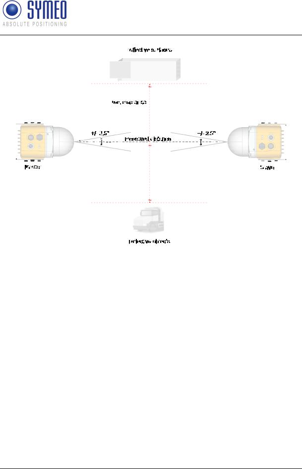
3.4.2Secondary Radar Mode
In secondary radar mode two radars measure the distance and speed between each other. The following features differentiate the secondary radar mode from the other radar modes:
Suitable for ranges up to 300 m
Distance is always measured to the partner unit and not to passive objects
Figure 3.4 shows the typical setup of two LPR®-1DHP-260 radars for a secondary radar range measurement.
Radar Basics
Copyright © Symeo GmbH 2018
DOC.EDO.000341.WORK.EN_LPR-1DHP-200_Product-Documentation.docx
Page 11 of 71
SYMEO Local Positioning Radar System
Product Family LPR®-1DHP-200 – Product Documentation
Figure 3.4: Secondary radar mode measurement setup
3.4.3Diversity Radar Mode
In diversity radar mode four radar units are grouped into two pairs, which are mounted in a way that two secondary range measurements are performed side by side separated by a defined distance. The following features differentiate the diversity radar mode from the other radar modes:
Suitable for ranges up to 500 m
Distance is always measured to the partner unit and not to passive objects
No clearance to reflective surfaces / objects required (see chapter 5.1; Fresnel zone still needs to be free of obstacles)
If one of the two measurement paths fails, the system falls back to operation in secondary radar mode and is therefore still available (error is indicated in diversity status byte)
Figure 3.5 shows the typical setup of four LPR®-1DHP-281 radars for a diversity radar range measurement.
Radar Basics
Copyright © Symeo GmbH 2018
DOC.EDO.000341.WORK.EN_LPR-1DHP-200_Product-Documentation.docx
Page 12 of 71

SYMEO Local Positioning Radar System
Product Family LPR®-1DHP-200 – Product Documentation
Figure 3.5: Diversity radar mode measurement setup
3.5Bandwidth Modes
The LPR®-1DHP-200 is able to operate in the 57 - 64 GHz band. Depending on your used region and regulatory authority setting, a limited number of bandwidth modes are available for selection in the WebUI.
The selected bandwidth modes have impact on the accuracy, resolution and range of the radar. The dependency of performance and bandwidth mode with respect to regional restrictions is depicted in chapter 10. It is recommended to use the 0.5 GHz or 2 GHz bandwidth mode for standard applications.
Within a single bandwidth mode, multiple sync channels are available. For each channel block, the effective bandwidth of a sync channel reduces with increasing sync channel number.
3.6Accuracy
To maximize the accuracy of a LPR®-1DHP-200 measurement setup, different error sources which influence the accuracy need to be taken into account:
Mounting position
o Adhere to the mounting instructions (see chapter 5) to minimize systematic errors (e.g. horizontal or vertical offset and alignment).
Reflective surfaces and objects
o Reflections of the radar signal, e.g. from walls, can cause distance errors in primary and secondary radar mode which vary with the measured distance. Ensure the recommended clearance to surfaces and objects described in chapter 5.1 or use diversity radar mode to minimize errors caused by reflections.
Measurement noise
o Measurement noise caused by the radar itself is the lower limit to the overall accuracy. The noise will decrease with increasing bandwidth. For primary radar mode, noise will increase with range and decrease with target radar cross section
Radar Basics
Copyright © Symeo GmbH 2018
DOC.EDO.000341.WORK.EN_LPR-1DHP-200_Product-Documentation.docx
Page 13 of 71

SYMEO Local Positioning Radar System
Product Family LPR®-1DHP-200 – Product Documentation
(dependent on target size, shape and material). In secondary radar mode noise is constant within the specified range and will increase for ranges above.
Temperature drift
o Changes in device and air temperature can lead to measurement offsets of approx. +/-10mm. These errors vary slowly with time and can be countered by ensuring constant environmental conditions, running a warm up phase of 30 minutes before operation or by using a calibration reference.
3.7Range
To maximize the range of a LPR®-1DHP-200 measurement setup the following aspects have to be taken into account:
Mounting position
o Adhere to the mounting instructions (see chapter 5). Ensure minimum alignment error and vertical / horizontal offset and equal orientation (for secondary and diversity radar mode)
Fresnel zone
o Ensure the Fresnel zone is free of absorbing or reflecting objects
Reflective surfaces and objects
o Reflections of the radar signal, e.g. from walls, can lead to a reduction of the received signal strength and hence maximum range. Ensure the recommended clearance to surfaces and objects described in chapter 5.1 or use diversity radar mode to counter the effects caused by reflections
Target RCS (only primary radar mode)
o In primary radar mode the maximum range depends on the target RCS (radar cross section) which is a function of target size, material and shape. If the maximum range is required use targets with a high RCS (e.g. the corner reflector MTE000958)
VGA value
o For maximum range set the “VGA value” to the highest possible value that is allowed in you regulatory domain. The WebUI will use your region settings to limit the “VGA value” and hence range is reduced in certain regions (see chapter 10).
The minimum range of the sensors can be reduced to values below the specified minimum distance by adapting the “VGA value”, the “RX attenuator” and the threshold settings (for primary radar). This however affects the maximum range and the accuracy of the radar and shall therefore only be applied by trained personell.
Radar Basics
Copyright © Symeo GmbH 2018
DOC.EDO.000341.WORK.EN_LPR-1DHP-200_Product-Documentation.docx
Page 14 of 71

SYMEO Local Positioning Radar System
Product Family LPR®-1DHP-200 – Product Documentation
4Components
4.1Device Overview
The LPR®-1DHP-200 consists of the following parts (see Figure 4.1 and Figure 4.2):
Dielectric Lens (A1)
o focuses the radar beam
Metal gland (A2)
o fixes the lens to the housing with four screws o seals the device against water and dirt
o holds the inner parts of the device in place
Housing (A3)
o provides LEDs (B1) and a pressure equalization membrane (B2)
o provides the M12 power supply connector (C1) and the M12 Ethernet connector (C2) o provides 2 x 3 M6 screwing holes (B3) for mounting in the mounting bracket
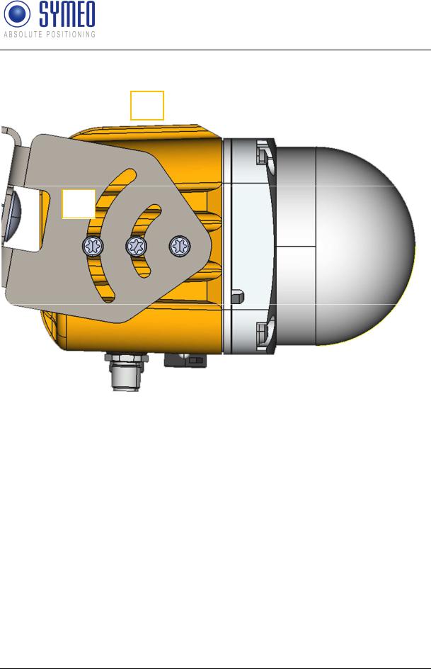
oprovides an adjustment guide for usage with a laser level for exact radar beam alignment (B4)
oensures IP65 protection class and heat dissipation
The housing must not be opened.
Components
Copyright © Symeo GmbH 2018
DOC.EDO.000341.WORK.EN_LPR-1DHP-200_Product-Documentation.docx
Page 15 of 71

SYMEO Local Positioning Radar System
Product Family LPR®-1DHP-200 – Product Documentation
A1
A2
B2 |
|
B1 |
|
|
|
B3 |
|
B3 |
|
|
|
A3 |
C2 |
C1 |
|
Figure 4.1: Front view of the LPR®-1DHP-200
Components
Copyright © Symeo GmbH 2018
DOC.EDO.000341.WORK.EN_LPR-1DHP-200_Product-Documentation.docx
Page 16 of 71
SYMEO Local Positioning Radar System
Product Family LPR®-1DHP-200 – Product Documentation
B4
B3
Figure 4.2: Side view of the LPR®-1DHP-200
Components
Copyright © Symeo GmbH 2018
DOC.EDO.000341.WORK.EN_LPR-1DHP-200_Product-Documentation.docx
Page 17 of 71
SYMEO Local Positioning Radar System
Product Family LPR®-1DHP-200 – Product Documentation
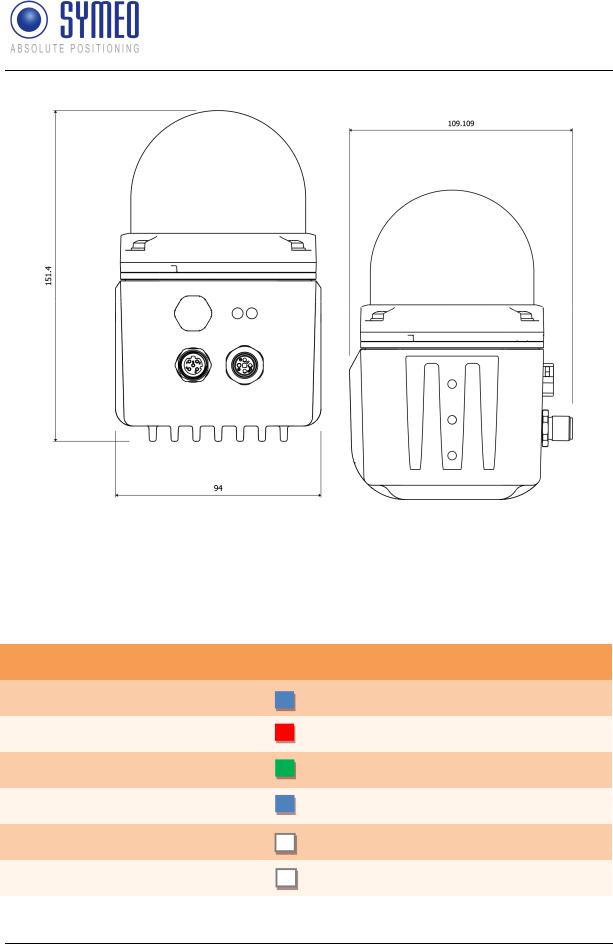
Figure 4.3: LPR®-1DHP-200 housing dimensions
4.2LED Display
The LEDs (Status LED on the left and Ethernet LED on the right) indicate the different states of the device (see Table 4.1).
LED Indication
Status LED lights up BLUE
Status LED lights up RED
Status LED lights up GREEN
Status LED flashes BLUE
Ethernet LED lights up WHITE
Ethernet LED flashes WHITE
Status of the Device
Device is booting up
Invalid measurement
Valid measurement
Firmware update in progress
Ethernet interface established
Ethernet interface transmits data
Table 4.1: LED Display
Components
Copyright © Symeo GmbH 2018
DOC.EDO.000341.WORK.EN_LPR-1DHP-200_Product-Documentation.docx
Page 18 of 71
SYMEO Local Positioning Radar System
Product Family LPR®-1DHP-200 – Product Documentation
4.3Connectors
The housing of the LPR®-1DHP-200 provides the following M12 connectors (see Figure 4.1 and Figure 4.2):
Power supply input (C1)
Ethernet connector (C2) for network connection
The necessary connectors for manufacturing cables that fit your installation and cable length are available from symeo and are described in the following chapters.
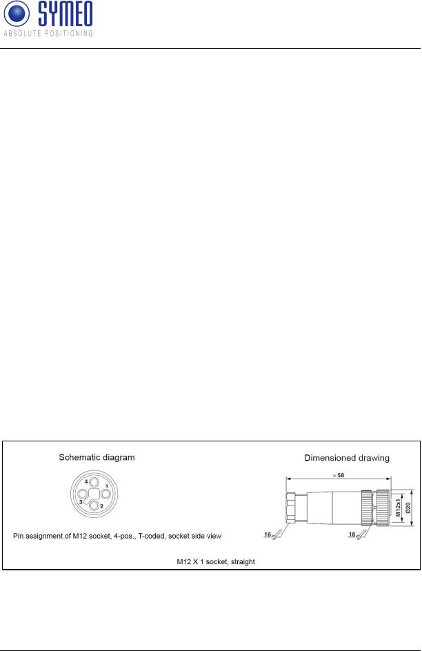
4.3.1Power Supply
The LPR®-1DHP-200 is powered by a 4-pin M12-Connector.
Plugs
Recommended connector:
SACC-M12FST-4PECON-PG 9-M – 1418052 (obsolete) SACC-M12FST-4CON-PG 9-M - 1418052
o Cable diameter: 6 - 8 mm Tightening torque: 0.4 Nm
o Symeo order number: MTE101761
The connector is also part of the following M12 connector set:
M12 connector set (Ethernet + Power supply)
oSymeo order number: MTE102366
Figure 4.4: M12 power supply connector
Components
Copyright © Symeo GmbH 2018
DOC.EDO.000341.WORK.EN_LPR-1DHP-200_Product-Documentation.docx
Page 19 of 71
|
|
|
SYMEO Local Positioning Radar System |
|
|
Product Family LPR®-1DHP-200 – Product Documentation |
|
|
|
|
|
|
Pin Assignment |
|
|
|
|
|
|
|
Power Supply 11 V DC – 36 V DC |
|
M12 Connector |
|
|
|
|
|
VDC+ |
|
Pin 1 |
|
|
|
|
|
VDC+ |
|
Pin 2 (bridged to Pin 1) |
|
|
|
|
|
VDC- |
|
Pin 3 |
|
|
|
|
|
VDC- |
|
Pin 4 (bridged to Pin 3) |
|
|
|
|
Table 4.2: Pin assignment power supply
4.3.2Ethernet M12
The LPR®-1DHP-200 can be connected to a LAN or a Profinet bus system (Production Code "n" required) via an M12 Ethernet Connector.
Plugs
Recommended connector:
SACC-M12MSD-4CON-PG 7-SH – 1521258
oCable diameter: 4 – 6 mm (PG7) Tightening torque: 0.4 Nm
oSymeo order number: MTE101768
o
The connector is also part of the following M12 connector set:
M12 connector set (Ethernet + Power supply)
oSymeo order number: MTE102366
Figure 4.5: M12 Ethernet connector
Components
Copyright © Symeo GmbH 2018
DOC.EDO.000341.WORK.EN_LPR-1DHP-200_Product-Documentation.docx
Page 20 of 71

SYMEO Local Positioning Radar System
Product Family LPR®-1DHP-200 – Product Documentation
Pin Assignment
Signal |
Color of Wire |
Color of Wire |
Pin Assignment |
|
PROFInet® |
EIA/TIA 568B |
|
|
|
|
|
TD+ |
Yellow |
White/Orange |
1 |
|
|
|
|
TD- |
Orange |
Orange |
3 |
|
|
|
|
RD+ |
White |
White/Green |
2 |
|
|
|
|
RD- |
Blue |
Green |
4 |
|
|
|
|
|
Table 4.3: Pin assignment for Ethernet M12 |
||
If the Ethernet connecter is left unused, install the protective cap of the connector.
Connector Cable M12 – RJ45
A connector cable M12 – RJ45 (2m) for connecting the radar to a PC for initial commissioning and configuration is available from Symeo:
Symeo order number: MTE102007
4.4Mounting Brackets
4.4.1Mounting Bracket – MTM102513
For mounting the LPR®-1DHP-200 to a pipe, a mounting bracket is available from Symeo. The pipe diameter should measure between 40 and 75 mm.
Components
Copyright © Symeo GmbH 2018
DOC.EDO.000341.WORK.EN_LPR-1DHP-200_Product-Documentation.docx
Page 21 of 71
 Loading...