


SYMEO LOCAL POSITIONING RADAR
Product: LPR-1DHP
Product Documentation

SYMEO Local Positioning Radar System
LPR-1DHP
Product Documentation
Content
1 OVERVIEW SAFETY .................................................................................................. 6
1.1 Safety Instructions .................................................................................................... 6
1.2 Installation ................................................................................................................. 6
1.3 Repairs....................................................................................................................... 6
1.4 Transport and Storage .............................................................................................. 6
1.5 Power Supply ............................................................................................................ 7
1.6 Setup and Operation ................................................................................................. 7
1.7 System Extensions and Accessories ...................................................................... 7
1.8 Additional Instructions Regarding LPR-1DHP station............................................ 8
1.9 Important Information to User .................................................................................. 8
2 OVERVIEW OF THE LPR-1DHP SYSTEM ................................................................ 9
2.1 Data sheet of LPR-1DHP Station ............................................................................ 10
2.2 Opening angle LPR-1DHP station .......................................................................... 10
2.3 Mounting position of the LPR-1DHP stations ....................................................... 11
3 COMPONENT SETUP OF THE LPR-1DHP STATION ............................................. 12
3.1 Overview .................................................................................................................. 12
3.2 Front element .......................................................................................................... 13
3.2.1 LED display ............................................................................................................... 13
3.2.2 Other parts ................................................................................................................ 13
3.3 Rear elements ................................ ................................................................ ......... 14
3.3.1 LPR-1DHP station with TCP/IP interface................................................................... 14
4 ELECTRICAL CONNECTIONS ................................................................................ 15
4.1 LPR-1DHP station with TCP/IP interface ............................................................... 15
4.1.1 Electrical connection ................................................................................................. 15
4.1.2 Mode of operation ..................................................................................................... 15
4.2 LPR-1DHP configuration with USB interface ........................................................ 16
4.2.1 Electrical connection ................................................................................................. 16
4.2.2 Mode of operation ..................................................................................................... 16
Overview Safety
Copyright © Symeo GmbH 2012
Page 2 of 40

SYMEO Local Positioning Radar System
LPR-1DHP
Product Documentation
5 MOUNTING .............................................................................................................. 17
6 COMMISSIONING LPR-1DHP WITH TCP/IP INTERFACE ...................................... 18
6.1 Requirements .......................................................................................................... 18
6.2 Connection to LPR-1DHP Station .......................................................................... 18
7 WEB SERVER FOR LPR-1DHP UNITS WITH TCP/IP INTERFACE ........................ 20
7.1 Open Web Server .................................................................................................... 20
7.2 Settings.................................................................................................................... 21
7.2.1 „LAN“ area ................................................................................................................ 22
7.2.2 „Network“ Area .......................................................................................................... 23
7.2.3 „Serial-to-Ethernet“ Area ........................................................................................... 24
7.2.3.1 ttyS2 / Parameterization Port .................................................................................... 24
7.2.3.2 ttyS3 / Binary Port ..................................................................................................... 24
7.2.4 „Remote Access“ Area .............................................................................................. 25
7.2.5 „Miscellaneous“ Area ................................................................................................ 26
7.2.6 „Special Functions“ Area ........................................................................................... 26
7.2.7 Accept settings / System Reboot .............................................................................. 27
7.3 System Status ......................................................................................................... 27
7.4 Diagnostics ............................................................................................................. 29
7.5 Update Firmware ..................................................................................................... 30
7.5.1 Step 1 – File system.................................................................................................. 31
7.5.2 Step 2 – Linux Kernel ................................................................................................ 32
7.5.3 Step 3 – Optional: Userspace ................................................................................... 35
7.5.4 Step 4 – Restart ........................................................................................................ 35
7.6 System Log ............................................................................................................. 35
8 PROTOCOL XP DESCRIPTION FOR TCP/IP AND RS232 ...................................... 37
8.1 General Description ................................................................................................ 37
8.1.1 Structure of Data Packet ........................................................................................... 37
8.1.2 Byte Stuffing ............................................................................................................. 37
8.1.3 CRC .......................................................................................................................... 38
8.2 Data Types ............................................................................................................... 38
8.2.1 Type 0x00 – Distance Data ....................................................................................... 38
8.2.2 Example of Distance Data ......................................................................................... 39
8.3 Binary protocol XP over TCP/IP: Fixed Frame Protocol ................................ ....... 39
8.3.1 Detailed description TCP Fixed-Frame Protocol ........................................................ 39
8.3.2 Detailed description UDP Fixed-Frame Protocol ....................................................... 40
8.4 Error messages ....................................................................................................... 40
Overview Safety
Copyright © Symeo GmbH 2012
Page 3 of 40

SYMEO Local Positioning Radar System
LPR-1DHP
Product Documentation
Overview Safety
Copyright © Symeo GmbH 2012
Page 4 of 40
SYMEO Local Positioning Radar System
Version
Date
Description
1.10
06.02.2012
Documentation for FCC
This symbol appears before instructions that must be followed at all times.
Failure to comply with these instructions will result in personal injury.
This symbol appears before instructions that must be followed at all times.
Failure to comply with these instructions will result in damage to
equipment.
This symbol appears before information of particular importance.
LPR-1DHP
Product Documentation
The documentation for the LPR-1DHP Local Positioning Radar System is published by:
SYMEO GmbH
Prof.-Messerschmitt-Str. 3
D-85579 Neubiberg
www.symeo.de
If you have any questions or suggestions, please contact:
Email: info@symeo.com
phone: +49 89 660 7796 0
Copyright Symeo GmbH 2012
All rights reserved
HISTORY
SYMBOLS USED
The following symbols are used throughout the documentation:
All rights reserved, particularly those relating to the translation, reprinting, and reproduction
by photocopying or similar processes of all or part of the documentation.
All rights reserved, particularly for purposes of the award of patents or submission of utility
models.
Delivery options and technical changes reserved.
Published by SYMEO GmbH
Overview Safety
Copyright © Symeo GmbH 2012
Page 5 of 40
SYMEO Local Positioning Radar System
LPR systems are purely tracking and assistance systems. They
therefore do not satisfy the safety class 3 requirements and must not be
used as standalone systems in safety-critical applications, such as
automation or anti-collision.
Follow the safety instructions in the operating instructions for the device
and the additional documentation!
All installation, repair and servicing work must be carried out by qualified
and trained technicians!
When the system is mounted on fixed tubes the necessary measures to
prevent slippage of the system must be taken
Repairs of the device must be carried out by authorized technicians.
Unauthorized opening and incorrect repairs could result in severe
danger to the user (danger of electric shock, radiated energy, fire
hazard).
Use the original packaging or other suitable packaging for returns and
whenever the system is to be transported. This ensures protection from
crushing, impacts, moisture and electrostatic discharge.
During setup and before operation, refer to the instructions for
environmental conditions included in the operating instructions for the
device.
Route the wires in such a way that they do not cause a hazard and are
not damaged. When connecting the wires, refer to the corresponding
instructions in the operating instructions for the device.
Do not drop the device and do not expose it to strong vibrations.
Product Documentation
1 Overview Safety
1.1 Safety Instructions
Keep these safety instructions and other documents together with the device.
1.2 Installation
LPR-1DHP
1.3 Repairs
1.4 Transport and Storage
Copyright © Symeo GmbH 2012
Page 6 of 40
Overview Safety
A safety-inspected power cable that satisfies the regulations of the
country of use is required for the device. Devices with metal housings
must only be connected to a grounded, shock proof socket.
The device must not be operated unless the nominal voltage of the
device matches the local supply voltage. Check the supply voltage of
the device in stationary devices.
When connecting and disconnecting wires, refer to the instructions in
the operating instructions for the device.
Do not use any damaged wires (damaged insulation, exposed wires). A
faulty wire poses a risk of electric shock or fire hazard.
Polarity reversal or otherwise faulty connection can damage the LPR1DHP station. In that case the station must be send to the SYMEO
service.
During installation, make sure that no objects or fluids enter the device
(risk of electric shock, short circuit).
In emergencies (e. g. if there is damage to the housing, control
elements or the mains cable, if fluids or foreign bodies have infiltrated
the equipment), switch off the power supply to the device immediately
and notify your SYMEO Service.
Protect the contacts of all of the device's sockets and plugs from static
electricity. Do not touch the contacts. If it is ever necessary to touch the
contacts, take the following precautionary measures: Touch a grounded
object or carry a ground strap before touching the contacts. This will
divert static charges.
Proper operation (in accordance with IEC60950/EN60950) of the device
is only assured if the housing and integral covers for mounting slots are
fully installed (electric shock, cooling, fire protection, noise suppression).
If necessary, refer to the corresponding instructions in the operating
instructions for the device.
In the case of high outside temperatures and intense, direct solar
radiation or other radiant heat, it may be necessary to provide a sun or
heat shield.
Data links to peripheral devices must be provided with adequate
shielding.
For LAN cabling, the requirements in accordance with EN 50173 and
EN 50174-1/2 apply. Use of either a Category 5 shielded cable for
10/100 Ethernet or Category 5e shielded cable for gigabit Ethernet is a
minimum requirement. The specifications of standard ISO/IEC 11801
1.5 Power Supply
SYMEO Local Positioning Radar System
LPR-1DHP
Product Documentation
1.6 Setup and Operation
1.7 System Extensions and Accessories
Copyright © Symeo GmbH 2012
Page 7 of 40
Overview Safety

SYMEO Local Positioning Radar System
must be complied with.
The warranty shall be voided if you cause defects to the device by
installing or exchanging system extensions.
The LPR 1 DHP station must not be opened except for installation and
mounting. The LPR 1DHP station contains no serviceable components.
When opening, ensure that no fluid gets into the housing. When sealing
the station, ensure that the seal is included in the rear element and that
the LPR 1 DHP station is completely closed. Otherwise, moisture can
penetrate the station and damage it.
In order to install the LPR 1DHP station, the rear element must be
detached from the front element. Refer also to the instructions on
installing the station.
The printed circuit board stack connected to the front element does not
require user service and must remain attached to the front element.
Please take note of the safety and operating instructions in the
operating instructions for the system in which you want to install the
component.
Product Documentation
1.8 Additional Instructions Regarding LPR-1DHP station
LPR-1DHP
1.9 Important Information to User
Any change or modification not expressly approved by the party
rsponsible for compliance could void the user's authority to operate the
equipment.
Copyright © Symeo GmbH 2012
Page 8 of 40
Overview Safety
SYMEO Local Positioning Radar System
A1
A2
A2
A2
A2
C
B1
B
A
LPR-1DHP
Product Documentation
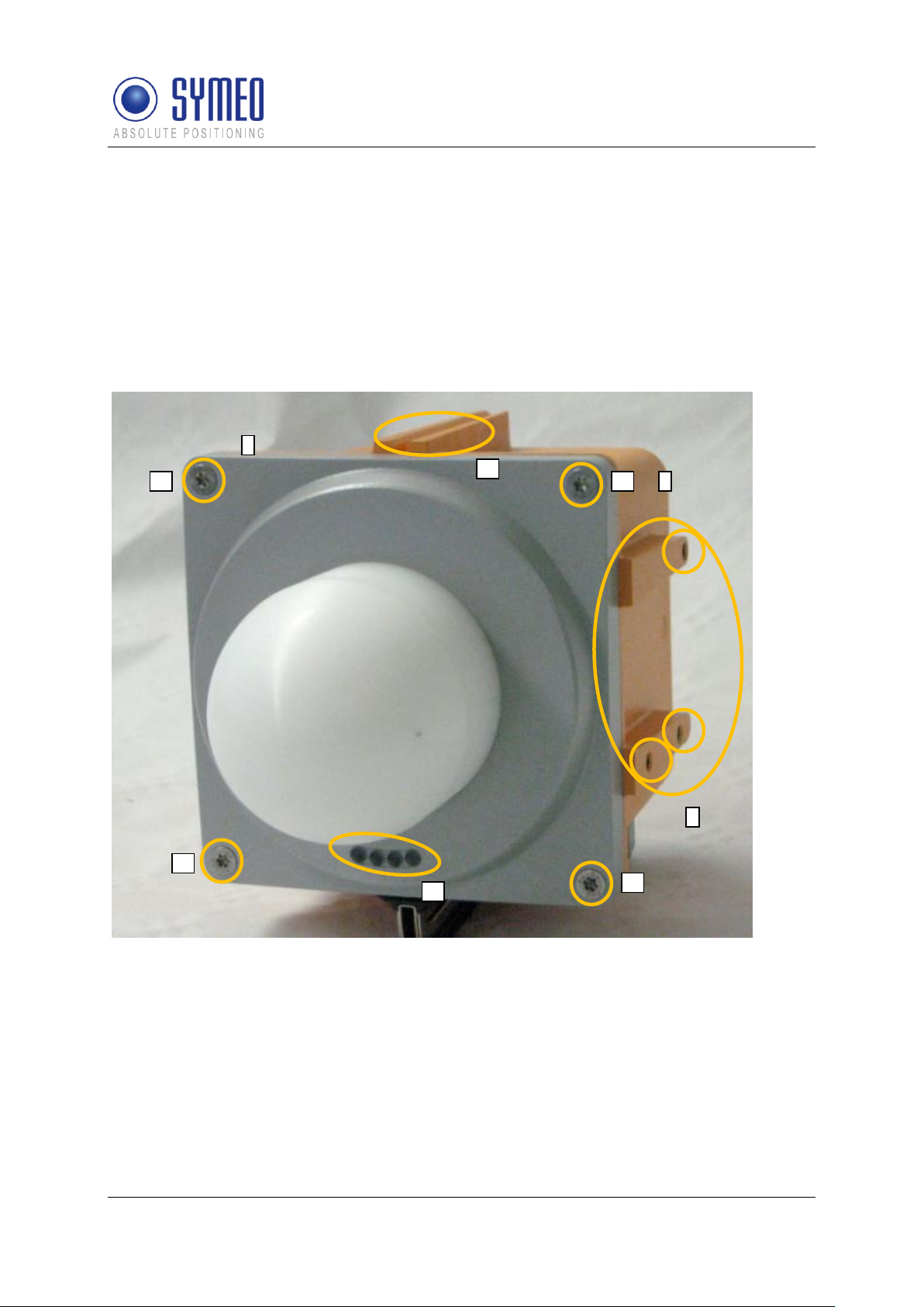
2 Overview of the LPR-1DHP system
An LPR-1DHP system consists of two units named BS and TS that conduct the
measurements. One unit (BS) initiates the measurement and the second unit (TS) replies.
Both units are shipped in a pre-configured set. Unit BS1 is configured to measure with TS1,
BS2 with TS2 and so on. The distance values are only available on the unit labeled BS.
Consequently, the unit BS must be mounted at the position where the distance values are
required, e.g. on the crane-bridge. Figure 1 shows the complete system including mounting
bracket for mounting on tubes.
Figure 1: LPR 1DHP station consisting of
A: Front element with display (A1) and fixing screws for front element (A2)
B: Rear element with alignment aid (B1)
C: Holes for mounting bracket.
Overview of the LPR-1DHP system
Copyright © Symeo GmbH 2012
Page 9 of 40
Overview: Technical Data
Frequency range
61.000 MHz - 61.500 MHz
Transmitting power
20dBm EIRP
Measuring distance
up to 500 m *1
Typical accuracy
Up to ± 1 cm *1
Repeat rate
Max. 25 Hz
Power supply
10-36 V DC
Power consumption
Max. 15 W
Ambient temperature
-40°C to +75°C
Protection class
IP 65 with suitable cables (round, outside diameter
4.5 – 10 mm)
Casing dimensions(LxWxH);
205 x 140 x 140 mm
Weight
0,9kg
Hardware Interface
Ethernet TCP/IP or UDP
USB (Configuration)
Data interface
Symeo LPR-1D protocol
Antenna
integrated
Compliance
FCC (Part 15.255)
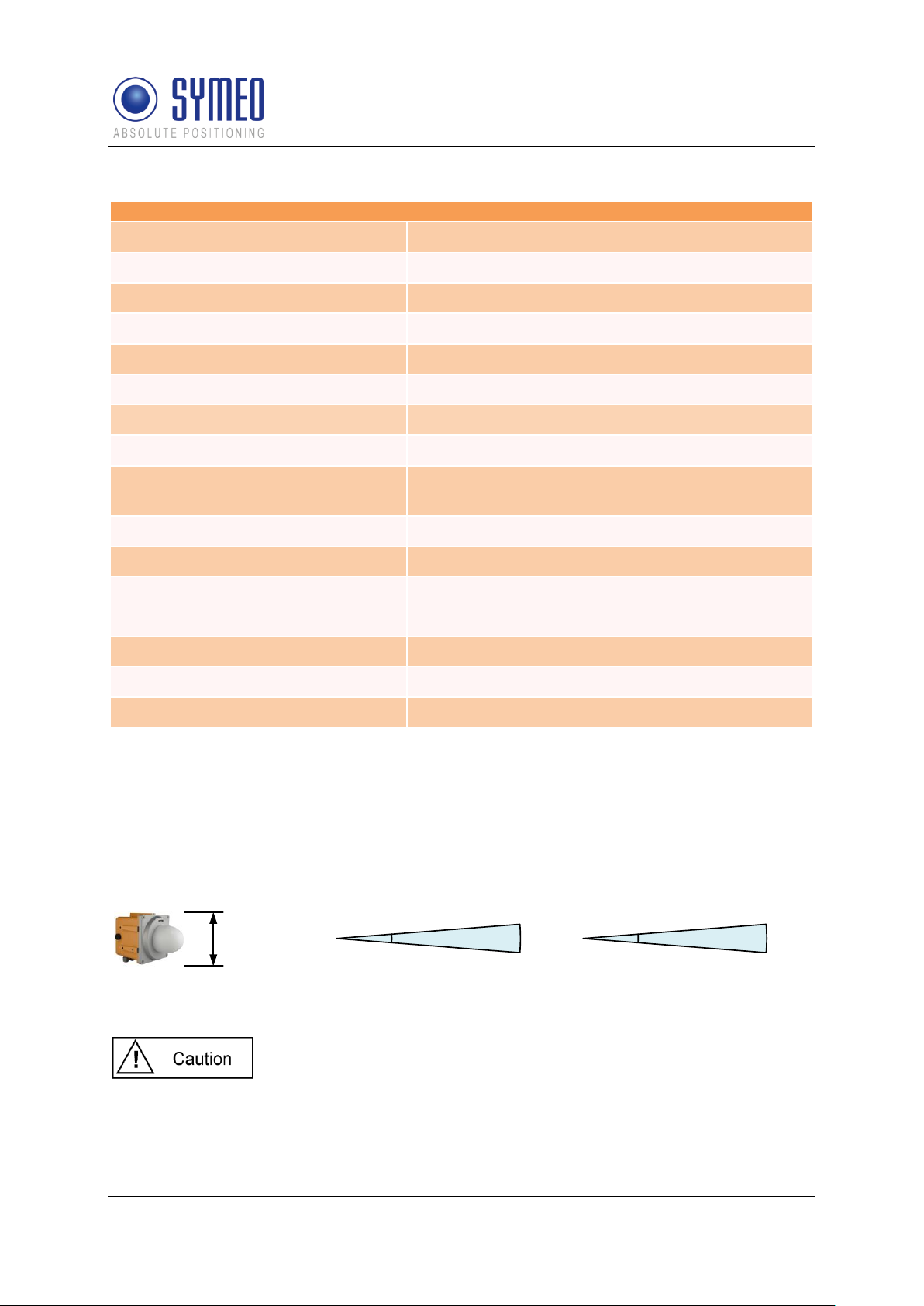
To achieve operation and range as specified both system units must
have the same orientation, e.g. LED display oriented towards the roof
or the same wall.
LPR 1DHP Station
A
A = 140mm
Integrated antenna
horizontal
4°
-3 dB
0 dB
-3 dB
vertical
4°
-3 dB
0 dB
-3 dB
2.1 Data sheet of LPR-1DHP Station
SYMEO Local Positioning Radar System
LPR-1DHP
Product Documentation
*1 Depending on the application conditions
2.2 Opening angle LPR-1DHP station
The LPR-1DHP station has an integrated antenna with +/-2° opening angle.
Figure 2: Opening angle LPR 1DHP station
Copyright © Symeo GmbH 2012
Page 10 of 40
Overview of the LPR-1DHP system

SYMEO Local Positioning Radar System
LPR-1DHP
Product Documentation
2.3 Mounting position of the LPR-1DHP stations
The stations must be aligned with each other for proper measurement. In addition the
following topics must be considered:
Site-specific mounting instructions must be followed when available.
A minimum distance of 2 meters between the two system units must be maintained to
guarantee the specified accuracy.
Minimum distance of 50 cm between adjacent systems must be used to avoid cross-
interference.
The two system units must be mounted opposite to each other with less than 10 cm
horizontal or vertical offset.
The stations must be aligned with an accuracy better than +/- 2°.
The orientation of the stations must be the same, e.g. both units with LED-display
oriented to the roof or to the same wall.
Overview of the LPR-1DHP system
Copyright © Symeo GmbH 2012
Page 11 of 40
SYMEO Local Positioning Radar System
A
A3
A4
B
C
C1
C1
B1
B4
B4
B2
B3
B5
B6
A5
LPR-1DHP
Product Documentation
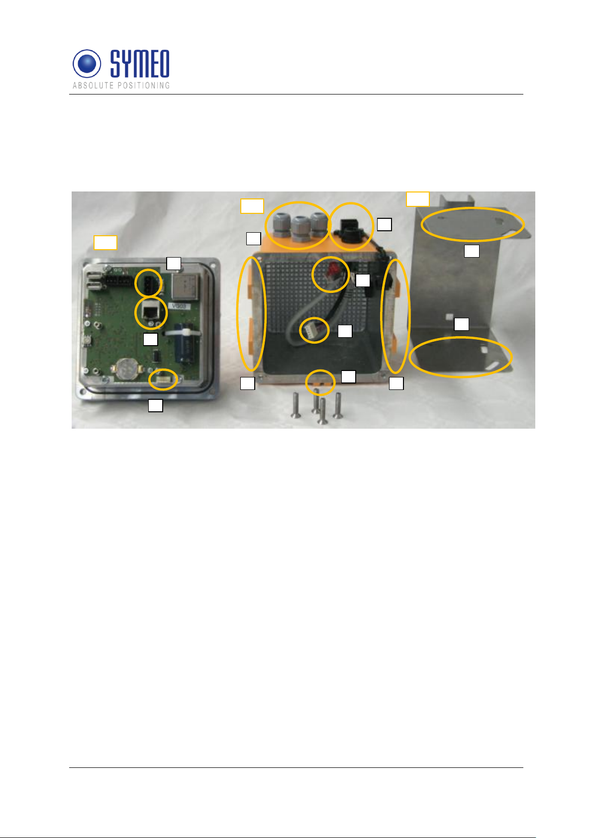
3 Component setup of the LPR-1DHP station
3.1 Overview
The LPR-1DHP station consists of front element A, rear element B and mounting bracket C
as shown in Figure 3.
Figure 3: System components front element A, rear element B and mounting bracket C
A: front element
A3 ethernet connector (version TCP/IP)
A4 terminal for power connection
A5 header for USB cable
B: rear element
B1 alignment aid
B2 ethernet connector system (version TCP/IP)
B3 cable feedthrough for power supply and auxiliary cables
B4 insert nut M6 for mounting the system in the mounting bracket
B5 ethernet connector front to rear element (version TCP/IP)
B6 USB connector for USB service port
C: mounting bracket
C1 mounting slots for system unit
Important parts not shown in Figure 3 like the LED display (A1) are displayed in Figure 1.
Component setup of the LPR-1DHP station
Copyright © Symeo GmbH 2012
Page 12 of 40

SYMEO Local Positioning Radar System
A
A4
A3
A8
A9
LPR-1DHP
Product Documentation
3.2 Front element
The front element is composed of the following parts:
RF-support element, RF-board, IF-board, power supply and dielectric lens
Support element with housing screws (A2, see Figure 1)
Supply board including power supply terminal (A4), ethernet connector (A3) and USB
connector (A5)
LED display (A1, see Figure 1)
3.2.1 LED display
The LEDs on the operating display indicate different statuses of the device as follows:
When the system is powered, the red LED is turned on.
When both units are connected to the supply power and valid measurements are made
the green LED is turned on or blinking with low frequency.
Network traffic is indicated with the orange LED for a station with TCP/IP interface
3.2.2 Other parts
The only parts that are important for mounting and commissioning are the housing screws
(A2), the terminal for the power supply (A4), the ethernet connector (A3) for version TCP/IP
and the USB header (A5). The seal (A8) seals front and rear element when the system is
mounted correctly.
Replace the fuse (A9) only with a fuse of the same type and rating (3A normal blow).
Figure 4: Front element of the LPR-1DHP station (version TCP/IP)
Component setup of the LPR-1DHP station
Copyright © Symeo GmbH 2012
Page 13 of 40

SYMEO Local Positioning Radar System
B
B3
B7
B2
B6
B4
LPR-1DHP
Product Documentation
3.3 Rear elements
The rear element (B) carries the front element (A) and is mounted in the mounting bracket
(C).
3.3.1 LPR-1DHP station with TCP/IP interface
The rear element of the LPR-1DHP station with TCP/IP interface provides the following
connections (see
Figure 5):
Ethernet connector (B2) for Network connection: type Harting push pull, available from
SYMEO as MTE000060 plug RJ45.
power supply and auxiliary feedthroughs (B3)
insert nuts M6 (B4) for mounting in the mounting bracket
pressure equalization membran (B6)
USB connector (B7)
Figure 5: Rear element of the LPR-1DHP station
Component setup of the LPR-1DHP station
Copyright © Symeo GmbH 2012
Page 14 of 40

SYMEO Local Positioning Radar System
All installation, repair and servicing work must be carried out by
qualified and trained technicians!
The diameter of all cables fed through cable glands must be within 4.5
to 10 mm, and have a round cross-section.
The pressure equalization membran (B6) must not be removed or
loosened. Otherwise the housing will not be sealed in a water-proof
manner.
Polarity reversal or otherwise faulty connection can damage the LPR1DHP station.
A4
A3
1
2
3
+
-
+
LPR-1DHP
Product Documentation
4 Electrical connections
4.1 LPR-1DHP station with TCP/IP interface
4.1.1 Electrical connection
Power supply is connected using the power supply terminal (A4), Ethernet is connected to socket
(A3).
Figure 6 depicts the pin assignment of (A4): Positive voltage can be connected either at pin 1
or 3, the negative or ground voltage is connected to pin 2.
Figure 6: Electrical connections
4.1.2 Mode of operation
For standard operation of LPR-1DHP stations with TCP/IP interface the rotary switch (S2)
has to be set to position 3 (see Figure 6).
Electrical connections
Copyright © Symeo GmbH 2012
Page 15 of 40

SYMEO Local Positioning Radar System
Polarity reversal or otherwise faulty connection can damage the LPR1DHP station.
B2
B6
+ - +
A4
LPR-1DHP
Product Documentation
4.2 LPR-1DHP configuration with USB interface
4.2.1 Electrical connection
Power supply is connected using the power supply terminal (A4), USB is connected using
terminal (B6).
Figure 7 depicts the pin assignment of (A5). The pin assignment of (A4) is similar to (A4) as
described in section 4.1.1.
Figure 7: Electrical connections
4.2.2 Mode of operation
For configuration of LPR-1DHP stations with USB interface the rotary switch (S2) has to be set to
position 0 (see Figure 7).
Electrical connections
Copyright © Symeo GmbH 2012
Page 16 of 40

SYMEO Local Positioning Radar System
When the system is mounted on fixed tubes the necessary
measures to prevent slippage of the system must be taken
All installation, repair and servicing work must be carried out by
qualified and trained technicians!
A lot of the terms used in the following description are explained in
Figure 1 and Figure 3.
Avoid entry of foreign objects or liquids into the system unit,
especially on the PCB stack of front element (A) or within rear
element (B).
It is important that both units have the same orientation, e.g. the
display of both units facing the ceiling.
Careful mounting of the system is required. It is important that the
joint (A6) remains clean and is not damaged, otherwise the
protection class cannot be guaranteed.
LPR-1DHP
Product Documentation
5 Mounting
The LPR-1DHP station (front and rear element) is delivered pre-mounted, and with a
separate mounting bracket. Figure 1 shows the complete system including mounting bracket.
The mounting bracket must be mounted with a separte pipe clamp on a pipe. For mounting
the system please proceed as follows:
Please use a torx wrench type T25 to remove the front element A from the rear element
B by loosening of the mounting screws (A2). If necessary you can disconnect the
ethernet cable (B5) from the front element (A3) to be more flexible.
Insert the power supply cable in the cable feedthrough (B3) and connect it to the power
supply terminal (A4) on the rear element (A); siehe Figure 6.
Reinsert the Ethernet connector (B5) of the rear element (B) into the connector (A3) of
front element (A). Mount the front element (A) on the rear element (B). It might be
necessary to tighten the inserted power cable.
Fix the front element on the rear element with the housing screws (A2) using a torx
wrench T25.
Carefully tighten the cable feedthrough with flat wrench SW19.
Mount the mounting bracket (C) on a pipe installed at a suitable place. Do not tighten the
screws of the pipe-clamp yet, the system must be aligned first.
Mount the LPR-1DHP station in the mounting bracket (C). When tightening the screws in
the mounting slot (C1) make sure that you can still align the system unit.
Carefully align both units. To do so, it is recommended to use a laser level fitted into the
alignment aid (B1).
Finally fix the system by tightening the screws of the mounting bracket and the pipe
clamp. Flat wrench SW 11 and 13 are required.
Copyright © Symeo GmbH 2012
Page 17 of 40
Mounting

SYMEO Local Positioning Radar System
With delivery the LPR-1DHP stations have the fixed IP-Address
192.168.1.99, if no other IP-Address is labeled outside the LPR-1DHP
station.
You can change the IP-Address of the LPR-1DHP station via the web
interface of the LPR-Station.
To get a connection between your PC and the LPR-1DHP station it is
maybe neccessary to change the network parameters of your computer.
Both units must be loctaed in the same network. That means in this
example that the first three numeric pads of both IP-addresses must be
the same.
Figure 8 – Network Settings
Enter the following fixed IPAddress i.e. 192.168.1.1.
The subnet mask should be
set to 255.255.255.0.
Click in both windows OK.
LPR-1DHP
Product Documentation
6 Commissioning LPR-1DHP with TCP/IP interface
6.1 Requirements
In order for a station to be successfully commissioned, the LPR-1DHP components must
have been installed correctly:
The station has been installed.
The station has been connected to the power supply.
Data link has been established over TCP/IP.
Once these prerequisites have been fulfilled, you can connect the station to the network and
commission the LPR-1DHP system. How to do this is explained in the following chapters.
6.2 Connection to LPR-1DHP Station
Disconnect your PC from the network. Connect the LPR-1DHP station and the computer with
a network cable. Open your network settings of your computer.
Copyright © Symeo GmbH 2012
Page 18 of 40
Commissioning LPR-1DHP with TCP/IP interface

SYMEO Local Positioning Radar System
LPR-1DHP
Product Documentation
If you firewall settings are too restrictive, you may not get access to the
LPR-1DHP station. In this case deactivate the firewall temporarely under
the tab Advanced.
The LPR Station should be available via your PC now. You can check the connection with a
ping to the LPR-1DHP station:
Open the Command-Window:
1. Push the Windows Start Button
2. Choose Run
3. Enter cmd and click OK
4. Enter in the cmd.exe window: ping 192.168.1.99 or the IP-address of the LPR-1DHP
station.
Figure 9 – Ping LPR-1DHP Station
The LPR-1DHP Station should answer with a Reply.
Commissioning LPR-1DHP with TCP/IP interface
Copyright © Symeo GmbH 2012
Page 19 of 40

SYMEO Local Positioning Radar System
The IP-address of the LPR-1DHP station is 192.168.1.99 per delivery
status except another IP-address is labeled outside the box.
You can establish a connection with your LPR-1DHP stations Web
server either via HTTP or HTTPS if the station has been configured for
this; see section "Settings", "HTTP" and "HTTPS" fields in the "Remote
Access" area.
In HTTP connections, the data is transmitted unencrypted. In HTTPS
connections, it is encrypted for transmission (AES-256, 256-bit
encryption).
A connection is established with your LPR1DHP station.
In the case of an HTTPS connection, you
may see two dialog boxes. Confirm them
both with OK.
Then the Welcome page for the LPR-1DHP
station's Web server will appear.
You will be prompted to enter your information
for authentication.
Enter user name symeo and the password,
and click OK. The password has been set
to 54all2u by the manufacturer.
LPR-1DHP
Product Documentation
7 Web Server for LPR-1DHP units with TCP/IP
interface
Having a LPR-1DHP station with TCP/IP interface the network settings for this station are
described in this chapter.
Therefore it is necessary to open a TCP/IP connection between your computer and the LPR1DHP station.
7.1 Open Web Server
Open your web browser. In the address bar of the web browser enter the IP-address of
the LPR-1DHP station: http://192.168.1.99 or https://192.168.1.99. Press Enter.
Click the function you want in the navigation bar. The individual functions are described in
the following sections.
Web Server for LPR-1DHP units with TCP/IP interface
Copyright © Symeo GmbH 2012
Page 20 of 40

SYMEO Local Positioning Radar System
In order to protect your system from being reconfigured by unauthorized
persons, change this to a company password that is only provided for
authorized personnel; see section „Remote Access“ Area, table row
Password from page 25.
7.2 Settings
With this function you can
define the network settings on your LPR-1DHP station,
define the network access settings,
reboot the system,
restore the default settings
download a configuration backup
LPR-1DHP
Product Documentation
Click Settings in the navigation bar.
If you have not yet provided authentication information you will be prompted to do so
now; see chapter 7.1.
The Settings page for the LPR-1DHP station's Web server is displayed as follows.
Web Server for LPR-1DHP units with TCP/IP interface
Copyright © Symeo GmbH 2012
Page 21 of 40

SYMEO Local Positioning Radar System
Structure of the Settings page:
LAN:
Overview about LAN settings of
LPR-1DHP station (static or
dynamic IP address); see chapter
7.2.1.
Network:
Network settings; see chapter
7.2.2.
Serial-to-Ethernet:
Settings of parameterization port
and the data interface; see chapter
7.2.3.
Remote Access:
See chapter 7.2.4.
Miscellaneous:
Setting of time zone; see chapter
7.2.5.
Special Functions:
See chapter 7.2.6.
MACAddress
Unique hardware address of the LPR-1DHP station on the LAN (Ethernet
ID), (IEEE registered MAC adress, not editable)
Current
Mode
Shows the current mode:
"Static IP-Address" or "DHCP Active". Per default the IP-address is set to
the static IP-address 192.168.1.99.
In "DHCP Active" mode, the LPR-1DHP station receives a dynamic or
reserved IP address from the DHCP server. You can also ask your
administrator or the SYMEO technical department about this.
LPR-1DHP
Product Documentation
Press button Upload changes to accept the changes of the LPR-1DHP station.
Press button Reboot System to reboot the LPR-1DHP station with the new settings.
7.2.1 „LAN“ area
Copyright © Symeo GmbH 2012
Page 22 of 40
Web Server for LPR-1DHP units with TCP/IP interface

SYMEO Local Positioning Radar System
If the LPR-1DHP station is set to „DHCP“ but does not
receive an IP-address from the DHCP server within 60 sec
after the reboot the last applied fixed IP-address is used.
Change
Mode
A button is labeled "DHCP" or "Static" depending on the "Current mode"
field. Click this button to switch from "DHCP Active" mode to "Static IPAddress" mode or vice versa.
IP-Address
IP address of the LPR-1DHP station
In "DHCP Active" mode, this address is assigned by the server and cannot
be edited.
In "Static IP-Address" mode you can assign a fixed (static) address here.
Netmask
Net mask of the LPR-1DHP station
(default: 255.255.255.0)
In "DHCP Active" mode, the net mask is assigned by the server and cannot
be edited.
Gateway
IP address of the standard gateway
(default: 192.168.98.254)
Other LAN segments can be reached with the standard gateway.
In "DHCP Active" mode this address is assigned by the server and cannot
be edited.
Hostname
Hostname of the system (default: "lprb-basestation").
In "DHCP Active" mode, this hostname is also communicated to the
DHCP/DNS server.
A name that will be reserved on the DNS server can be entered here. You
can also ask your administrator or the SYMEO technical department about
this.
DNS
IP address of the DNS server:
The DNS server is able to translate hostnames into IP addresses.
In "DHCP Active" mode this address is assigned by the server and cannot
be edited.
Syslog
IP address of the Syslog server (default: 0.0.0.0, i.e. this service has been
disabled).
The Syslog server is a server in the network provided to receive system
messages (system log). Transmission is packet-based (UDP) and
unencrypted.
NTP
IP address of the NTP server (default: 0.0.0.0, i.e. this service has been
disabled).
The NTP server is a server on the network from which the system can
request the current time.
LPR-1DHP
Product Documentation
7.2.2 „Network“ Area
Copyright © Symeo GmbH 2012
Page 23 of 40
Web Server for LPR-1DHP units with TCP/IP interface

SYMEO Local Positioning Radar System
ttyS2
Port number of the TCP/IP port designated for sending and receiving data
from serial port (ttyS2). ttyS2 is the port for the parameterization interface
(Service Port, default: 3045)
ttyS3
Port number of the TCP/IP port via which the data from serial port (ttyS3) is
sent and received. ttyS3 is the port for the data interface (Binary Port,
default: 3046)
IP (Server)
For all active connection types the IP-address of the server is
required to which the connection should be established.
Data Port
Port-Number of TCP/IP Port. Data of serial interface (ttyS3)
is sent and received. ttyS3 is the binary port. Default value is
3046.
Reverse Port
For all active connection types a reverse channel for data
transmission is required.
Packet Filter
If selected type “Fixed Frame” it is possible to filter packed
data. Default value is „none”. Example: “2,3” filters the data
type 0x02 (Send request) and data type 0x03 (relay switching
command).
Receive Size
If selected type “Fixed Frame” it is possible to set the frame
size of the received data packed. Example: For 1Dapplication a frame size of 15 Byte is sufficient. A smaller
telegram must me filled with 0x00.
Send Size
If selected type “Fixed Frame” it is possible to set the frame
size of the sent data packet. Example: For 1D-applicaiton a
frame size of 21 Byte is sufficient. A smaller telegram is filled
with 0x00 by the LPR-1DHP station.
Speed
Baud rate has to be set always to 19200
LPR-1DHP
Product Documentation
7.2.3 „Serial-to-Ethernet“ Area
For each port, select the connection type between the LPR-1DHP station and PC, SPS,
S7 from the Connection Type list. By default, both ports (ttyS2, ttyS3) are disabled. Due
to the selected connection type, different input masks are visible which are explained
below.
7.2.3.1 ttyS2 / Parameterization Port
This port is used for parameterization of stations by Symeo. Please do not use this port.
7.2.3.2 ttyS3 / Binary Port
Network Settings Area:
Serial Settings Area
Web Server for LPR-1DHP units with TCP/IP interface
Copyright © Symeo GmbH 2012
Page 24 of 40

Disabled
The port is „Disabled“ and not be reachable via TCP/IP.
TCP – Variable Frame –
Listening on Data Port
The LPR-1DHP station is waiting for incoming connection on
the “Data Port”. If the connection is opened successful you
can open the binary port. „Variable Frame“ means activated
„Byte Stuffing“ (no fixed protocol length).
TCP – Variable Frame –
Connecting to Data Port
The LPR-1DHP station establishes the connection to the
entered server IP-address. Setting “Random” means both
communication partners arrange the reverse channel
autonomously. If the connection is opened successful you
get access to the binary port. „Variable Frame“ means
activated „Byte Stuffing“ (no fixed protocol length).
TCP – Fixed Frame –
Listening on Data Port
The LPR-1DHP station is waiting for an incoming connection
on the “Data Port”. If the connection is opened successfully
you can open the binary port. „Fixed Frame“ means
deactivated „Byte Stuffing“ (fixed protocol length).
TCP – Fixed Frame –
Connecting to Data Port
The LPR-1DHP station establishes the connection to the
entered server IP-address. Setting “Random” means both
communication partners arrange the reverse channel
autonomously. If the connection is opened successful you
get access to the binary port. „ Fixed Frame“ means
deactivated „Byte Stuffing“ (fixed protocol length).
UDP – Fixed Frame –
Sending to Data Port
The LPR-1DHP station sends and receives data (UDP) to
and from the entered server IP-address. The reverse channel
uses also the data port. „Fixed Frame“ means deactivated
„Byte Stuffing“ (fixed protocol length).
Telnet
Click this checkbox to allow or prevent console accesses to port 23 via
Telnet (checked: accesses are allowed). The port number is not editable.
See also section "Extended system access".
SSH/SCP/SFTP
Click this checkbox to allow or prevent console accesses to port 22 via
SSH (Secure SHell and data transmission via SCP (Secure CoPy) or
SFTP (Secure File Transfer Protocol) (checked: accesses are allowed).
The port number is not editable. See also section "Extended system
access".
HTTP
Click this checkbox to permit or forbid accesses to the LPR-1DHP station's
Web server via HTTP (unencrypted transmission) (checked: accesses are
allowed). You must also enter the corresponding port number as
appropriate. The port number is set to 80 (http protocol standard) by the
manufacturer.
HTTPS
Click this checkbox to permit or forbid accesses to the LPR-1DHP station's
Web server via HTTPS (encrypted transmission) (checked: accesses are
allowed). You must also enter the corresponding port number as
appropriate. The port number is set to 443 (http protocol standard) by the
Connection Type Area
SYMEO Local Positioning Radar System
LPR-1DHP
Product Documentation
7.2.4 „Remote Access“ Area
Copyright © Symeo GmbH 2012
Page 25 of 40
Web Server for LPR-1DHP units with TCP/IP interface

SYMEO Local Positioning Radar System
manufacturer.
User
User ID for access to the TCP/IP port. It has been set to "symeo" by the
manufacturer and cannot be changed.
Password
Enter the new password here if you want to change the password. The
password has been set to "54all2u" by the manufacturer.
Repeat
Password
Enter the new password again here if you want to change the password.
Timezone
If a NTP-server is available and the IP-address of the NTP-server is entered
you can choose the time zone of the LPR-1DHP station. It is also possible
to enter the time zone manually.
Restore
default
Click this button to restore the settings made by the manufacturer.
Click the "Execute" button (Restore factory default settings) in the
"Special functions" area to cancel all changed settings and restore the
factory settings.
The settings made by the manufacturer are only activated after a reboot of
the LPR-1DHP station. This means that changes of the settings (i.e. IPaddress) are possible.
The settings affected will be deleted and set directly to the
factory settings.
When the factory settings have been restored, it may be
necessary to repeat the initial commissioning process of the system .
Reboot
system
To accept the settings the LPR-1DHP station must be rebooted. Click the
button “Reboot System” to reboot the system.
Before you reboot the system the settings must be loaded to
LPR-1DHP
Product Documentation
Extended system access („Remote Access“) enables console access via Telnet, SSH
(Secure SHell), SCP (Secure CoPy) and via the serial port. This enables extended system
information to be retrieved and troubleshooting to be carried out. We recommend that you
disable all functions that are not required..
In extended system access, the user "SYMEO" has 'ROOT' privileges, i.e.,
full access to the system. Depending on the settings made, the system can
also be damaged and such damage may or may not be reparable. If you
have any questions, please contact the SYMEO technical department.
The enormous range of functions that are available to console access means that only some
can be documented here. To find out more, please contact your IT administrator or Symeo
Support.
7.2.5 „Miscellaneous“ Area
7.2.6 „Special Functions“ Area
Copyright © Symeo GmbH 2012
Page 26 of 40
Web Server for LPR-1DHP units with TCP/IP interface

SYMEO Local Positioning Radar System
the LPR-1DHP station by pressing button “Upload
changes”.
Download
settings
Press the button „Download Settings“ to download a copy of the
configuration as a backup.
Press button „Upload changes“ to load
the changes.
Scroll down to the end of the page and
press „Reboot System“ to reboot the
LPR-1DHP station.
LPR-1DHP
Product Documentation
7.2.7 Accept settings / System Reboot
As described in chapter 7.2 it is necessary to transmit the changes to the LPR-1DHP station
and afterwards reboot the station.
7.3 System Status
With this function, you can display the current system status.
Web Server for LPR-1DHP units with TCP/IP interface
Copyright © Symeo GmbH 2012
Page 27 of 40

Click "Status" in the navigation bar.
If you have not yet provided
authentication information, you will be
prompted to do so now; see section
"Starting and using the Web server".
The Status page for the LPR-1DHP
station's Web server is displayed.
Uptime
01:27:47 – Current system time
up 20 min – Time since the last system start
load average: 0.00, 0.00, 0.00 – Average system load for the last 1, 5
and 15 minutes. The load indicates how many processes are waiting to
receive computing time
Memory (RAM)
MemTotal: Total usable working memory (physical RAM less a number
of reserved bits and the kernel code)
MemFree: Free working memory
Filesystem
Details about the active file systems and associated statistics.
OS Version
Operating system, kernel, compiler and compiling date
SVN Version
Current version of software
Description
Description of the system
System Date
Current system time
Watchdog
Status of the hardware watchdog, including counter of start operations
since the last switch-on (connection of the power supply). A value
between 2 and 127 means that the watchdog has triggered that number
of system restarts. The counter is reset at 'power-on-reset' (connection
of the power supply) and 'user-rest' (jumper on motherboard). In a
reboot (e.g. from the Web page), the current counter status is not reset.
CPU Info
Serial Number: Globally unique identification number of the processor
used (applied to each chip individually with a laser during production).
Silicon Revision: Version of the processor used
0x0 Rev. A
0x1 Rev. B
0x2 Rev. C
The fields have the following meanings:
SYMEO Local Positioning Radar System
LPR-1DHP
Product Documentation
Copyright © Symeo GmbH 2012
Page 28 of 40
Web Server for LPR-1DHP units with TCP/IP interface

0x3 Rev. D0
0x4 Rev. D1
0x5 Rev. E0
0x6 Rev. E1
0x7 Rev. E2
Connections: State of the active and inactive
connection to the LPR-1DHP station
Partitions: Size and name of available
partition of non-volatile memory.
Proto
Recv-Q
Send-Q
LocalAddress
Foreign
Address
State
tcp 0 0
0.0.0.0:3045
0.0.0.0:*
LISTEN
7.4 Diagnostics
SYMEO Local Positioning Radar System
LPR-1DHP
Product Documentation
The size of receive buffer (Recv-Q) and send buffer (Send-Q) should be
zero if possible. A long lasting value grater zero means problems when
receiving or sending data. This happens if the data cannot be readout fast
enough.
Example 1 – waiting for incoming connection:
If Connection Type „TCP - Listening on Data Port“ (ttyS2) is enabled this table shows further
connection information.
Proto: Protocol (TCP, UDP)
Recv-Q: Number of buffered Bytes, which are received from the LPR-1DHP station
Send-Q: Number of buffered Bytes, which the LPR-1DHP station should send
Local-Address: LPR-1DHP Interface address (0.0.0.0 – listening to all interfaces)
Foreign Address: IP-address of opposite station
State: Status of connection
Web Server for LPR-1DHP units with TCP/IP interface
Copyright © Symeo GmbH 2012
Page 29 of 40

SYMEO Local Positioning Radar System
Proto
Recv-Q
Send-Q
Local-Address
Foreign Address
State
tcp 0 1
192.168.1.99:3045
192.168.1.1:1333
ESTABLISHED
A firmware update is performed in several
steps:
Step 1: File system
Step 2: Linux-Kernel
Step 3: Optional (2D Application)
Step 4: Restart
Step 3 is exclusively for an
update for 2D application.
Otherwise this part can be
skipped.
LPR-1DHP
Product Documentation
Example 2: - successfully established connection
Of Connection Type „TCP - Listening on Data Port“ (ttyS2) is enabled this table shows
further connection information.
Proto: Protocol (TCP, UDP)
Recv-Q: Number of buffered Bytes, which are received from the LPR-1DHP station
Send-Q: Number of buffered Bytes, which the LPR-1DHP station should send
Local-Address: LPR-1DHP Interface address (192.168.1.99) with port (3045)
Foreign Address: IP-address of opposite station (192.168.1.1) with port (1333)
State: Status of connection
7.5 Update Firmware
With this function you can update the firmware.
The firmware can be updated for example when a firmware with improved functional scope is
available for the LPR system.
The system can also be irreparably damaged by a firmware update. Please
make absolutely sure that the files are correct (file names and the version
has been released by SYMEO), and proceed carefully and methodically. If
the firmware update has not been carried out properly, or if problems arise
of the system can no longer be accessed, contact Symeo Support.
Click "Firmware Update" in the navigation bar.
If you have not yet provided authentication information, you will be prompted to do so
now; see chapter 7.1.
The Firmware Update for the LPR-1DHP station's Web server is displayed.
Copyright © Symeo GmbH 2012
Page 30 of 40
Web Server for LPR-1DHP units with TCP/IP interface

Click the "Browse" button in the "Step 1
– flash ramdisk.gz" area.
A file browser window will open.
Navigate to the file you want and click
"Open".
Click the "Upload" button in the "Step 1 –
flash ramdisk.gz" area.
The file has been transferred.
Click the "back: Firmware Update" link.
7.5.1 Step 1 – File system
It is possible to make a copy of the actual firmware by downloading the
firmware from the LPR-1DHP station. Click the button „Backup ramdisk.gz“.
SYMEO Local Positioning Radar System
LPR-1DHP
Product Documentation
Web Server for LPR-1DHP units with TCP/IP interface
Copyright © Symeo GmbH 2012
Page 31 of 40

SYMEO Local Positioning Radar System
Click the "Execute" button in the "Step 1
– flash ramdisk.gz" area to transfer the
file to the non-volatile memory.
Transfer progress is displayed in a
message window.
You will know when this operation is
complete because a message: "... done,
file ramdisk.gz removed" will be output
and a link "back: Firmware Update" is
provided
Click the "back: Firmware Update" link.
LPR-1DHP
Product Documentation
7.5.2 Step 2 – Linux Kernel
It is possible to make a copy of the actual firmware by downloading the
firmware from the LPR-1DHP station. Click the button „Backup zImage “.
Web Server for LPR-1DHP units with TCP/IP interface
Copyright © Symeo GmbH 2012
Page 32 of 40

SYMEO Local Positioning Radar System
Click the "Browse" button in the "Step 2
– flash zImage" area.
A file browser window will open.
Navigate to the file you want and click
"Open".
Click the "Upload" button in the "Step 2 –
flash zImage" area.
The file has been transferred.
Click the "back: Firmware Update" link.
LPR-1DHP
Product Documentation
Web Server for LPR-1DHP units with TCP/IP interface
Copyright © Symeo GmbH 2012
Page 33 of 40

SYMEO Local Positioning Radar System
Click the "Execute" button in the "Step 2
– flash zImage" area to transfer the file
to the non-volatile memory.
Transfer progress is displayed in a
message window.
You will know when this operation is
complete because a message: "... done,
file zImage removed" will be output and
a link "back: Firmware Update" is
provided
Click the "back: Firmware Update" link.
LPR-1DHP
Product Documentation
Web Server for LPR-1DHP units with TCP/IP interface
Copyright © Symeo GmbH 2012
Page 34 of 40

SYMEO Local Positioning Radar System
To do this, click the " Reboot system "
button in the "Step 4 – Restart" area.
The system will be restarted.
If the new firmware contains
additional configuration files
the settings you made are
set to factory settings. This
applies also for the IPaddress which is set to the
default value 192.168.1.99.
Symeo recommends restoring the factory
settings after a firmware update (see section
7.2.6) and reenter the customer settings.
LPR-1DHP
Product Documentation
7.5.3 Step 3 – Optional: Userspace
This step is exclusively for 2D-applications necessary and is executed the same way as
described before.
7.5.4 Step 4 – Restart
To complete the firmware update, you must restart the system.
7.6 System Log
With this function, you can display the system messages (system log). The system
messages are written to a 200 KB capacity memory. When the memory is full, the oldest
messages are overwritten. All messages are deleted upon restart.
Copyright © Symeo GmbH 2012
Page 35 of 40
The system messages can also be transmitted to a server on the network
at the same time, see the "Syslog" field in the "Network" area in section
"Settings".
Web Server for LPR-1DHP units with TCP/IP interface

SYMEO Local Positioning Radar System
Click "System Log" in the navigation bar.
If you have not yet provided
authentication information, you will be
prompted to do so now; see chapter 7.1.
The last 10 system messages will be
displayed. The message window is
updated about once per second.
LPR-1DHP
Product Documentation
Copyright © Symeo GmbH 2012
Page 36 of 40
Web Server for LPR-1DHP units with TCP/IP interface

SYMEO Local Positioning Radar System
TYPE DATA
START
0x7e
1 byte 1 byte 1 byte
CRC
2 byte
END
0x7f
original symbol
replaced by
0x7D
0x7D 0x5D
0x7E
0x7D 0x5E
0x7F
0x7D 0x5F
LPR-1DHP
Product Documentation
8 Protocol XP Description for TCP/IP and RS232
8.1 General Description
This protocol is the interface between a LPR-1DHP station and the user. The binary protocol
XP protocol provides information in high density. Its structure ensures a simple
implementation. The transfer is done in single data frames.
The interface for the binary protocol XP can either be a serial (RS232) interface or a TCP/IP
or UDP interface. The baudrate of the serial interface must be set to 19200 baud.
8.1.1 Structure of Data Packet
The binary protocol XP was originally designed for transmission over RS232 interfaces.
When the protocol is used on a RS232 interface each data packet starts and ends with a
reserved symbol. This reserved symbol cannot appear in the data stream.
Figure 1 shows the general structure of the data packet.
Figure 1: Structure of data the packet
The START and the STOP-field is in each data packet the reserved symbol 0x7e and 0x7f.
TYPE indicates the type of the data packet. Therefore up to 256 different types can be
defined . The TYPE-field is followed by the DATA-field. The DATA field contains the real data
of the packet of the type TYPE. The CRC-field contains a check sum. The check sum is
applied to all previous data fields except the START and END data field.
All multi-byte integers (e.g. CRC field) are encoded in Network-Byte-Order (Big Endian).
8.1.2 Byte Stuffing
The two symbols 0x7E and 0x7F are unique for START and STOP-fields. If these symbols
occur within any other field (TYPE, DATA or CRC), they must be replaced by the following
order:
This byte stuffing scheme ensures that the receiver of the protocol can identify definitely the
START-field within a flow of data, even if the symbol of the start field occurs within the
DATA-field.
Example: If the symbol 0x7d is read, it must be cancelled. The following symbol must be
XOR combined with 0x20 to recreate the original symbol.
Protocol XP Description for TCP/IP and RS232
Copyright © Symeo GmbH 2010
Seite 37 von 40

SYMEO Local Positioning Radar System
Byte stuffing is deactivated for the fixed frame protocol (compare chapter
8.3).
Content
Length
Value
Data type
START
1
0x7E
TYPE
1
0x00
Internal service information
2
0x####
Internal service information
2
0x####
Internal service information
1
0x##
Distance [mm]
4
0x#### ####
signed integer
Velocity [mm/s]
4
0x#### ####
signed integer
Level [dB]
1
0x##
signed integer
Error
1
0x##
unsigned integer
Internal service information
1
0x##
CRC
2
0x####
END
1
0x7F
LPR-1DHP
Product Documentation
8.1.3 CRC
The CRC-16-IBM with polynomial x16+x15+x2+1 is used for the CRC. The CRC is calculated
over all data fields (TYPE and DATA), but not for the START and END field.
The CRC-calculation is only applied to the original symbols. The appropriate calculation for
coding must applied before byte stuffing. If receiving the data from the LPR-1DHP system
the byte stuffing must be resolved to get the original symbol. Then the CRC is updated with
the original symbol.
8.2 Data Types
8.2.1 Type 0x00 – Distance Data
Direction: LPR-1DHP → User
Total length without byte stuffing: 21 byte
Protocol XP Description for TCP/IP and RS232
Copyright © Symeo GmbH 2010
Seite 38 von 40

SYMEO Local Positioning Radar System
LPR-1DHP
Product Documentation
8.2.2 Example of Distance Data
7E 00 08 03 08 02 11 00 00 10 62 00 00 00 7A E6 00 00 AF C4 7F
Figure 10 - Protocol for a single 1D measurement
This protocol shows a simple example for 1D measurement.
Distance date:
7E 00 08 03 08 02 11 00 00 10 62 00 00 00 7A E6 00 00 AF C4 7F
7E
00
08 03
08 02
11
00 00 10 62
00 00 00 7A
E6
00
START byte
hex
TYPE (00: Distance Data)
hex
hex =
hex =
= 0001|0001
hex
= 230
hex
Error status: 0 means no error; unequal 0 means
hex
00001|0000000001|1
00001|0000000001|0
internal service information
bin
= 4194
hex
= 122
hex
Level: 230 – 256 = -26 dB
dec
Distance: 4194 mm
dec
Velocity: 122 mm/s
dec
internal service information
bin
internal service information
bin
error (error description see see chapter 8.4)
00
AF C4
7F
internal service information
hex
cyclic redundancy check
hex
END byte
hex
8.3 Binary protocol XP over TCP/IP: Fixed Frame Protocol
If the LPR-1DHP station has a TCP/IP interface two options are available for the protocol.
Either you use the protocol as it is sent from the serial interface (with different data type
lengths, byte stuffing) or you use a fixed frame protocol.
In the first case the data symbols 0x7e und 0x7f (which are reserved for the START and
END field) are replaced (see chapter 8.1.2.) Byte stuffing causes a different protocol length.
For the fixed frame protocol each LPR-1DHP data packet is filled up with zero bytes to a
fixed length of bytes (i.e. 87 bytes) before the data packet is sent. Byte stuffing does not
occur. The START and the END byte are still used but not clear anymore due to not applying
byte stuffing. The fixed length of the data packets can be set on the web-interface of the
LPR-1DHP unit.
If TCP/IP is used the transmitted data have already a checksum. Therefore the checksum in
the protocol is not as important as for the serial interface.
8.3.1 Detailed description TCP Fixed-Frame Protocol
If a TCP fixed-frame protocol is used, a working TCP connection between the PC and the
LPR unit has to be guaranteed. Depending on the configuration of the LPR protocol
Protocol XP Description for TCP/IP and RS232
Copyright © Symeo GmbH 2010
Seite 39 von 40

SYMEO Local Positioning Radar System
Content
Source
Description
Value
no error
Measurement valid
0x00
no peak detected
Base Station
No measurement signal
0x01
peak too low
Base Station
Measurement signal is imprecise
0x02
nothing received
Transponder
No measurement data received
0x03
implausible speed
Base Station
Velocity is to high
0x04
measurement botched
Base Station
Measurement is not feasible.
0x05
no occupying received
Master Transponder
Measurement channel is not
reserved
0x06
no results received
Master Transponder
No measurement data received
0x07
Trigger
Transponder
Unit did not attend the
measurement
0x08
LPR-1DHP
Product Documentation
converter either the connection to a port on the LPR has to be initialized from the PC or the
LPR unit is establishing a connection to a PC.
If the connection is established, the PC has to read the data from the LPR in fixed data
length (i.e. 89 bytes). The first byte is always the START-byte and the second byte is always
the TYPE-byte. The relevance of the following data is depending on the data type. Because
no byte stuffing occurs the content for a special data type is always constant. For example
the measured velocity of the distance data is always written in data bytes 12-15
8.3.2 Detailed description UDP Fixed-Frame Protocol
If a UDP fixed frame protocol is used, the IP and the UDP port of the PC has to be
configured in the LPR protocol inverter. The converter sends each data packet as a UDP
packet of a fixed length (89 byte) to the PC. Compared to the TCP fixed frame option the
UDP fixed frame does not verify if the data packed arrived. The content is the same as for
the TCP fixed frame protocol.
8.4 Error messages
The distance data contains an error field which indicates the status of the message. The
following errors can occur:
Copyright © Symeo GmbH 2010
Seite 40 von 40
Protocol XP Description for TCP/IP and RS232
 Loading...