


SYMEO L
OCAL POSITIONING RADAR
Product Family: LPR®-1DHP-200
Products:
LPR®-1DHP-220-R
LPR®-1DHP-260
LPR®-1DHP-281
LPR®-1DHP-290
Product Documentation

SYMEO Local Positioning Radar System
Product Family LPR®-1DHP-200 – Product Documentation
Content
CONTENT .............................................................................................................................. 2
1 SAFETY NOTES ........................................................................................................ 6
2 THE LPR®-1DHP-200 PRODUCT FAMILY ................................................................. 8
3 RADAR BASICS ........................................................................................................ 8
3.1 Radar Distance Measurement Principle .................................................................. 8
3.2 Radar Beam and Opening Angle .............................................................................. 9
3.3 Fresnel Zone.............................................................................................................. 9
3.4 Radar Modes ........................................................................................................... 10
3.4.1 Primary Radar Mode ................................................................................................. 10
3.4.2 Secondary Radar Mode ............................................................................................ 11
3.4.3 Diversity Radar Mode................................................................................................ 12
3.5 Bandwidth Modes ................................................................................................... 13
3.6 Accuracy .................................................................................................................. 13
3.7 Range ....................................................................................................................... 14
4 COMPONENTS ........................................................................................................ 15
4.1 Device Overview ..................................................................................................... 15
4.2 LED Display ............................................................................................................. 18
4.3 Connectors .............................................................................................................. 19
4.3.1 Power Supply ............................................................................................................ 19
4.3.2 Ethernet M12 ............................................................................................................ 20
4.4 Mounting Brackets .................................................................................................. 21
4.4.1 Mounting Bracket – MTM102513 .............................................................................. 21
4.4.2 Diversity Mounting Bracket – MTM102512 ................................................................ 23
4.5 Corner Reflectors .................................................................................................... 23
4.5.1 Corner reflector 500mm – MTE000958 ..................................................................... 23
4.5.2 Corner reflector 250mm – MTE001011 ..................................................................... 24
4.5.3 Mount for corner reflector – MTM000169 .................................................................. 24
5 MOUNTING .............................................................................................................. 25
Content
Copyright © Symeo GmbH 2018
DOC.EDO.000341.WORK.EN_LPR-1DHP-200_Product-Documentation.docx
Page 2 of 71

SYMEO Local Positioning Radar System
Product Family LPR®-1DHP-200 – Product Documentation
5.1 General Mounting Instructions .............................................................................. 25
5.2 Mounting for Primary Radar Mode ......................................................................... 25
5.3 Mounting for Secondary Radar Mode .................................................................... 26
5.4 Mounting for Diversity Radar Mode ....................................................................... 27
6 QUICK SETUP ......................................................................................................... 27
6.1 Initial Setup ............................................................................................................. 27
6.2 Quick Setup for Primary Radar Mode .................................................................... 27
6.3 Quick Setup for Secondary Radar Mode ............................................................... 28
6.4 Quick Setup for Diversity Radar Mode .................................................................. 28
6.5 Review and Calibration of the Measurement Setup .............................................. 28
7 ESTABLISHING A TCP/IP CONNECTION ............................................................... 29
8 DEVICE SETUP VIA THE WEB USER INTERFACE................................................ 31
8.1 Open the Web User Interface ................................................................................. 31
8.2 Sign In ...................................................................................................................... 33
8.3 Initial Operation ....................................................................................................... 33
8.4 Change Settings, Review and Save Changes ....................................................... 36
8.5 Home Page .............................................................................................................. 38
8.1 Device ...................................................................................................................... 41
8.1.1 Device - Settings ....................................................................................................... 41
8.1.2 Device - Upload Configuration .................................................................................. 50
8.1.3 Device - Downloads .................................................................................................. 50
8.1.4 Device - Firmware Update......................................................................................... 50
8.1.5 Device - Factory Reset .............................................................................................. 51
8.1.6 Device - Reboot Device ............................................................................................ 51
8.2 Diagnostics ............................................................................................................. 52
8.2.1 Diagnostics – Operating System Status .................................................................... 52
8.2.2 Diagnostics – Hardware Status ................................................................................. 54
8.2.3 Diagnostics – Storage Devices ................................................................................. 55
8.2.4 Diagnostics – Range Measurement Statistics ........................................................... 55
8.2.5 Diagnostics – Record Measurement Data ................................................................. 59
8.2.6 Diagnostics – Packet Inspector ................................................................................. 59
Content
Copyright © Symeo GmbH 2018
DOC.EDO.000341.WORK.EN_LPR-1DHP-200_Product-Documentation.docx
Page 3 of 71

SYMEO Local Positioning Radar System
Product Family LPR®-1DHP-200 – Product Documentation
8.2.7 Diagnostics – Station Scan ....................................................................................... 60
9 THE CUSTOMER PROTOCOL ................................................................................ 62
9.1 General Description ................................................................................................ 62
9.1.1 Structure of a Data Type ........................................................................................... 62
9.1.2 CRC .......................................................................................................................... 62
9.2 Data Types ............................................................................................................... 63
9.2.1 Type 0x16 – Distance Data ....................................................................................... 63
9.2.2 Type 0x03 – Relays Switching Commands ............................................................... 65
9.2.3 LPR®-1D24 Address ................................................................................................ 67
10 TECHNICAL DATA .................................................................................................. 68
10.1 General Technical Data .......................................................................................... 68
10.2 Product Name vs. Model Number .......................................................................... 68
10.3 Mode Dependent Technical Data ........................................................................... 69
10.3.1 Primary Radar Mode ................................................................................................. 69
10.3.2 Secondary Radar Mode ............................................................................................ 69
10.3.3 Diversity Radar Mode................................................................................................ 70
11 TROUBLESHOOTING .............................................................................................. 71
12 APPLICATIONS ....................................................................................................... 71
Content
Copyright © Symeo GmbH 2018
DOC.EDO.000341.WORK.EN_LPR-1DHP-200_Product-Documentation.docx
Page 4 of 71
SYMEO Local Positioning Radar System
Product Family LPR®-1DHP-200 – Product Documentation
The documentation for the LPR®-1DHP-200 Local Positioning Radar System is published by:
SYMEO GmbH
Prof.-Messerschmitt-Str. 3
D-85579 Neubiberg
www.symeo.com
If you have any questions or suggestions, please contact:
Email: info@symeo.com
phone: +49 89 660 7796 0
Copyright Symeo GmbH
HISTORY
Version Date Description
0001 28.05.2018 Initial Release
0002 09.08.2018 Comprehensive update
WORK
SYMBOLS USED
The following symbols are used throughout the documentation:
This symbol appears before instructions that must be followed at all times.
Failure to comply with these instructions will result in personal injury.
This symbol appears before instructions that must be followed at all times.
Failure to comply with these instructions will result in damage to
equipment.
This symbol appears before information of particular importance.
All rights reserved, particularly those relating to the translation, reprinting, and reproduction
by photocopying or similar processes of all or part of the documentation and for purposes of
the award of patents or submission of utility models.
Delivery options and technical changes reserved.
Wherever the term LPR®-1DHP-200 is used during this documentation, all products included
in the LPR®-1DHP-200 product family are addressed.
Application specific documentation can be obtained from the Partner Login under
www.symeo.com or from Symeo support.
Content
Copyright © Symeo GmbH 2018
DOC.EDO.000341.WORK.EN_LPR-1DHP-200_Product-Documentation.docx
Page 5 of 71
SYMEO Local Positioning Radar System
Product Family LPR®-1DHP-200 – Product Documentation
1 Safety Notes
General
The LPR®-1DHP-200 product family is a radar distance measurement sensor that may be
used to measure distances between a radar unit and a reflector or between two radar units.
LPR®-1DHP-200 radars are purely tracking and assistance systems.
They do not satisfy special requirements for personal or functional
safety or explosion protection.
All personnel that commission or operate an LPR®-1DHP-200 radar
have to be instructed that it does not satisfy norms and requirements for
functional safety (e.g. IEC 61058, EN ISO 13849, EN 62061).
Read the documentation before operation of the radar and follow the
included safety notes.
Take note of the safety and operating instructions of the system in
which you want to install the device.
Follow national safety norms and regulations.
Installation
Installation must be carried out by qualified and trained technicians.
When the system is mounted on fixed tubes, the necessary measures to
prevent slippage of the system must be taken.
Only screwed connections with safety against loosening may be used
for mounting the radar.
Adhere to the specified tightening torques for all screws and connectors.
Screwed connections must be examined at regular intervals, especially
if the radar is mounted exposed.
Repairs and Modifications
Repairs or modifications may only be performed by the manufacturer.
Opening of the device is prohibited.
Any change or modification not expressly approved by the party
responsible for compliance could void the user’s authority to operate the
equipment.
The warranty shall be voided if you cause defects to the device by
installing or exchanging system extensions.
Safety Notes
Copyright © Symeo GmbH 2018
DOC.EDO.000341.WORK.EN_LPR-1DHP-200_Product-Documentation.docx
Page 6 of 71
Transport and Storage
Do not drop the device and do not expose it to strong vibrations.
Power Supply
While installing or using it in open-air, transient overvoltage cannot be
excluded. Overvoltage protection is to be used for low voltage in
accordance to DIN EN 61643-21 and IEC 61643-21.
Be careful that the device can be damaged by reverse polarity despite
implementation of polarity reversal protection.
Setup and Operation
Protect the contacts of all of the device's sockets and plugs from static
electricity.
Proper operation (in accordance with IEC60950/EN60950) of the device
is only assured if the housing and integral covers for mounting slots are
fully installed (electric shock, cooling, fire protection, noise suppression).
SYMEO Local Positioning Radar System
Product Family LPR®-1DHP-200 – Product Documentation
In case of intense, direct solar radiation or other radiant heat, it may be
necessary to provide a sun or heat shield.
Be aware, that misuse, modification or damage of the sensor can lead
to erroneous distance measurements.
After mounting and commissioning, compare the actual distance to the
distance measured by the radar sensor with respect to your needed
accuracy. This step must be repeated after major changes to your
measurement setup.
System Extensions and Accessories
For LAN cabling, the requirements in accordance with EN 50173 and
EN 50174-1/2 apply. Use of either a Category 5 shielded cable for
10/100 Ethernet or Category 5e shielded cable for gigabit Ethernet is a
minimum requirement. The specifications of standard ISO/IEC 11801
must be complied with.
General Requirements for Compliance of Radio Apparatus
The operation of this device requires compliance with regional radio
regulations.
This device complies with Part 15 of the FCC Rules and with Industry
Canada license-exempt RSS standard(s).
Le présent appareil est conforme aux CNR d'Industrie Canada applicables aux
appareils radio exempts de licence. L'exploitation est autorisée aux deux
conditions suivantes : (1) l'appareil ne doit pas produire de brouillage, et (2)
l'utilisateur de l'appareil doit accepter tout brouillage radioélectrique subi, même
si le brouillage est susceptible d'en compromettre le fonctionnement.
Copyright © Symeo GmbH 2018
DOC.EDO.000341.WORK.EN_LPR-1DHP-200_Product-Documentation.docx
Page 7 of 71

Exposure Requirements
To satisfy FCC exposure requirements a separation distance of 20 cm
or more should be maintained between the antenna of this device
and persons during operation.
To ensure compliance, operations at closer distances than this are not
recommended.
To satisfy ISED exposure requirements a separation distance of 20 cm
or more should be maintained between the antenna of this device
and persons during operation.
To ensure compliance, operations at closer distances than this are not
recommended.
Pour satisfaire aux exigences d'exposition ISED, une distance de sépa
ration de 20 cm ou plus doit être maintenue entre l'antenne de cet
appareil et les personnes pendant le fonctionnement.
Pour assurer la conformité, les opérations à plus courte distance ne
sont pas recommandées.
SYMEO Local Positioning Radar System
Product Family LPR®-1DHP-200 – Product Documentation
-
Copyright © Symeo GmbH 2018
DOC.EDO.000341.WORK.EN_LPR-1DHP-200_Product-Documentation.docx
Page
SYMEO Local Positioning Radar System
Primary Radar Mode
X
X
Secondary Ra
dar Mode
X
X
Diversity Radar Mode
X X X
Product Family LPR®-1DHP-200 – Product Documentation
2 The LPR®-1DHP-200 Product Family
The LPR®-1DHP-200 is a radar distance measurement sensor product family. The product
family consists of different product types, which are based on the same hardware platform.
Depending on your purchased product type, your radar provides one or more of three
different radar modes, namely a primary radar mode, a secondary radar mode and a
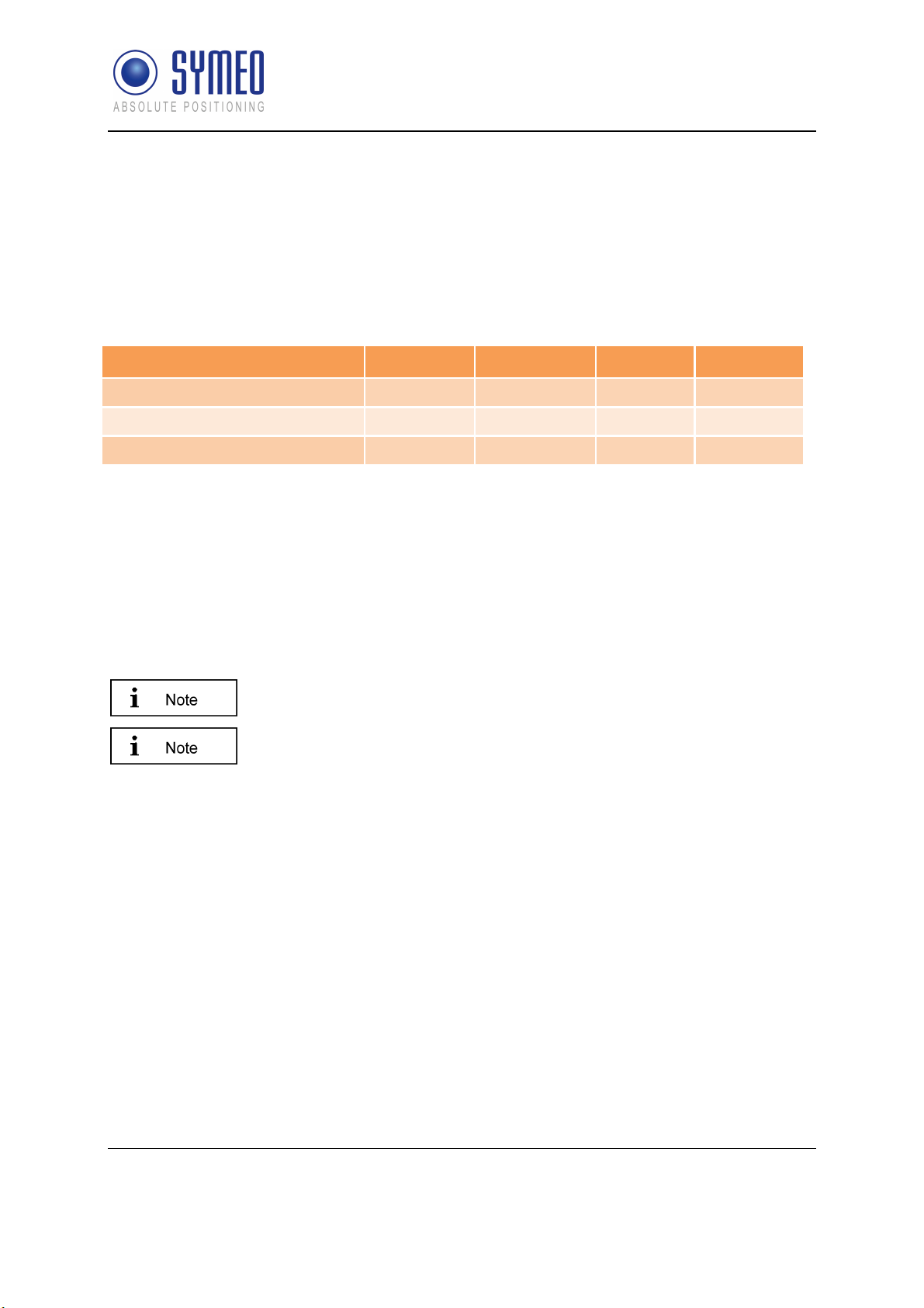
diversity radar mode. Table 2.1 shows the different product types and their supported radar
modes.
LPR®-1DHP- 220-R 260 281 290
Table 2.1: Supported radar modes for different LPR®-1DHP-200 product types.
Typical applications of the LPR®-1DHP-200 are:
Positioning of cranes, crane trolleys, hoists and other railbound transport systems
Process automation, monitoring and control
Collision avoidance
While reading this document keep in mind which radar modes are
supported by your device.
All LPR®-1DHP-200 product types can be configured with the help of a
Web User Interface (WebUI), which is described in chapter 8.
3 Radar Basics
3.1 Radar Distance Measurement Principle
The LPR®-1DHP-200 radar distance sensors use electromagnetic waves to measure the
distance and speed between two radars (secondary radar mode) or a single radar and a
reflector (primary radar mode).
The underlying measuring principle is based on the Round-Trip Time-Of-Flight (RTOF)
measurement between a transmitted radar signal and a received signal. The radar estimates
the time τ the radar signal needs to travel the unknown distance d from one radar to the other
(or to a reflector) and back. The distance is then calculated with the formula
where c is the speed of light.
Copyright © Symeo GmbH 2018
DOC.EDO.000341.WORK.EN_LPR-1DHP-200_Product-Documentation.docx
Page 8 of 71
= 0.5
Radar Basics
SYMEO Local Positioning Radar System
Product Family LPR®-1DHP-200 – Product Documentation
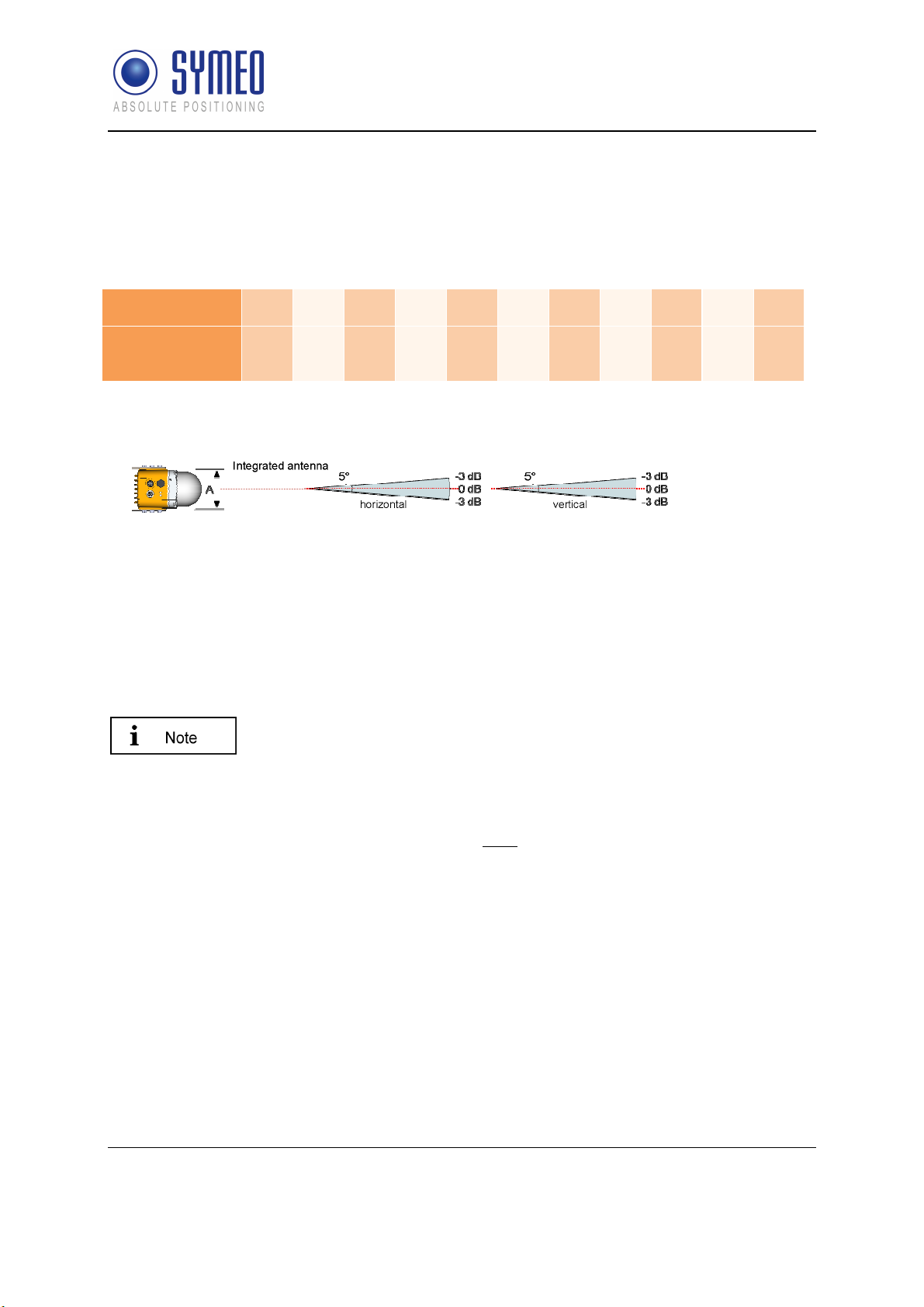
3.2 Radar Beam and Opening Angle
The LPR®-1DHP-200 emits a high frequency electromagnetic radio signal with its integrated
antenna. The EM-wave is focused by a dielectric lens and creates a radar beam with an
opening angle (half power beam width, HPBW) of +/-2,5°.
Distance d in m
Radar beam 3dB
diameter in m
1 3 10 30 50 70 100 200 300 400 600
0.1 0.3 0.9 2.6 4.4 6.1 8.7 17.5 26.2 34.9 52.4
Table 3.1: Radar beam 3dB diameter vs. distance
Figure 3.1: Radar beam and opening angle.
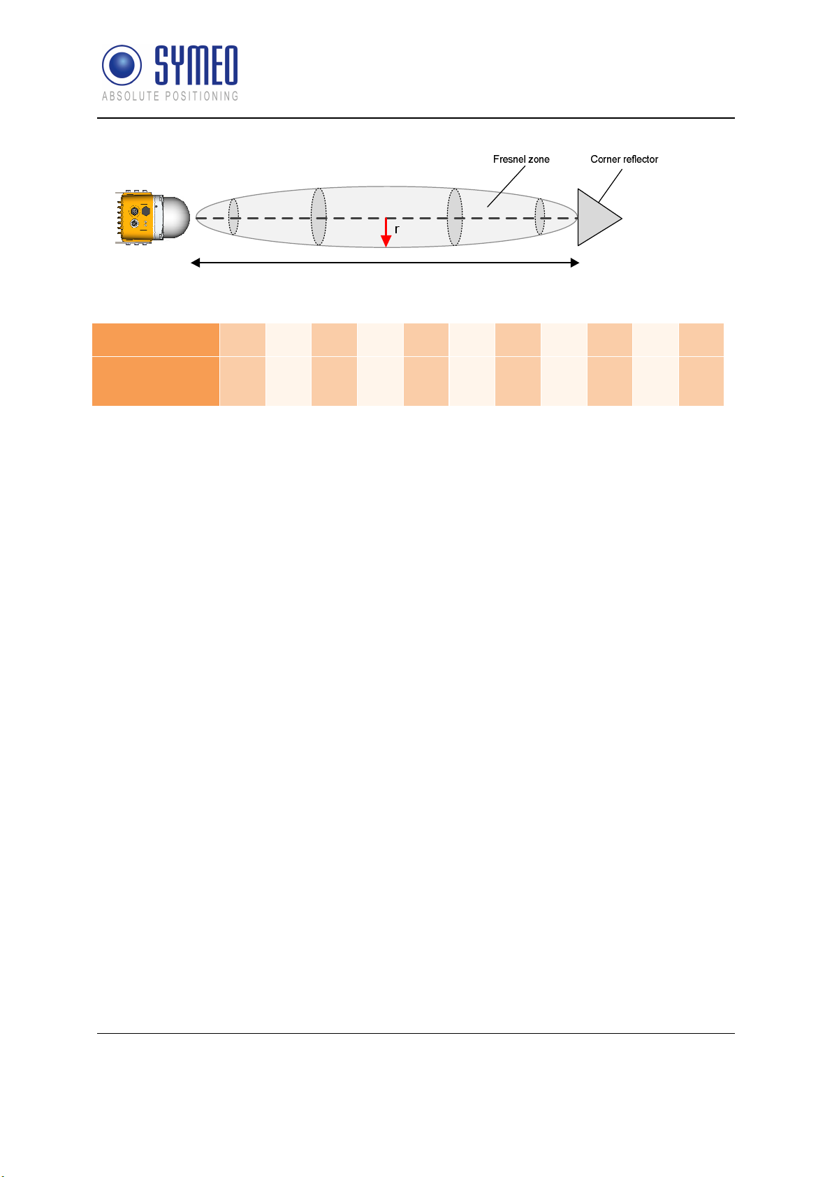
3.3 Fresnel Zone
The area for radio transmission between two antennas is called Fresnel zone. The main part
of energy is concentrated in the first Fresnel zone.
The Fresnel zone has to be free of any obstacles to ensure that the
signal is not attenuated or interrupted.
The maximum radius of the first Fresnel zone (in the middle between two antennas) can be
calculated as follows:
= 0.5 ∙√ ∙
is the wave length and the distance between the two radar devices or a radar device and
a reflective target For a frequency of 61 GHz a wave length of approx. 0.005 m is
calculated. The maximum radius of the first Fresnel Zone is indicated by . The maximum
radius for different distances is given in Table 3.2.
Radar Basics
Copyright © Symeo GmbH 2018
DOC.EDO.000341.WORK.EN_LPR-1DHP-200_Product-Documentation.docx
Page 9 of 71
SYMEO Local Positioning Radar System
Product Family LPR®-1DHP-200 – Product Documentation
Figure 3.2: Fresnel zone
Distance d in m
Fresnel Zone
Radius r in m
10 20 30 40 50 70 100 200 300 400 600
0.11 0.16 0.19 0.22 0.25 0.30 0.36 0.50 0.62 0.71 0.86
Table 3.2: Fresnel zone radius vs. distance
3.4 Radar Modes
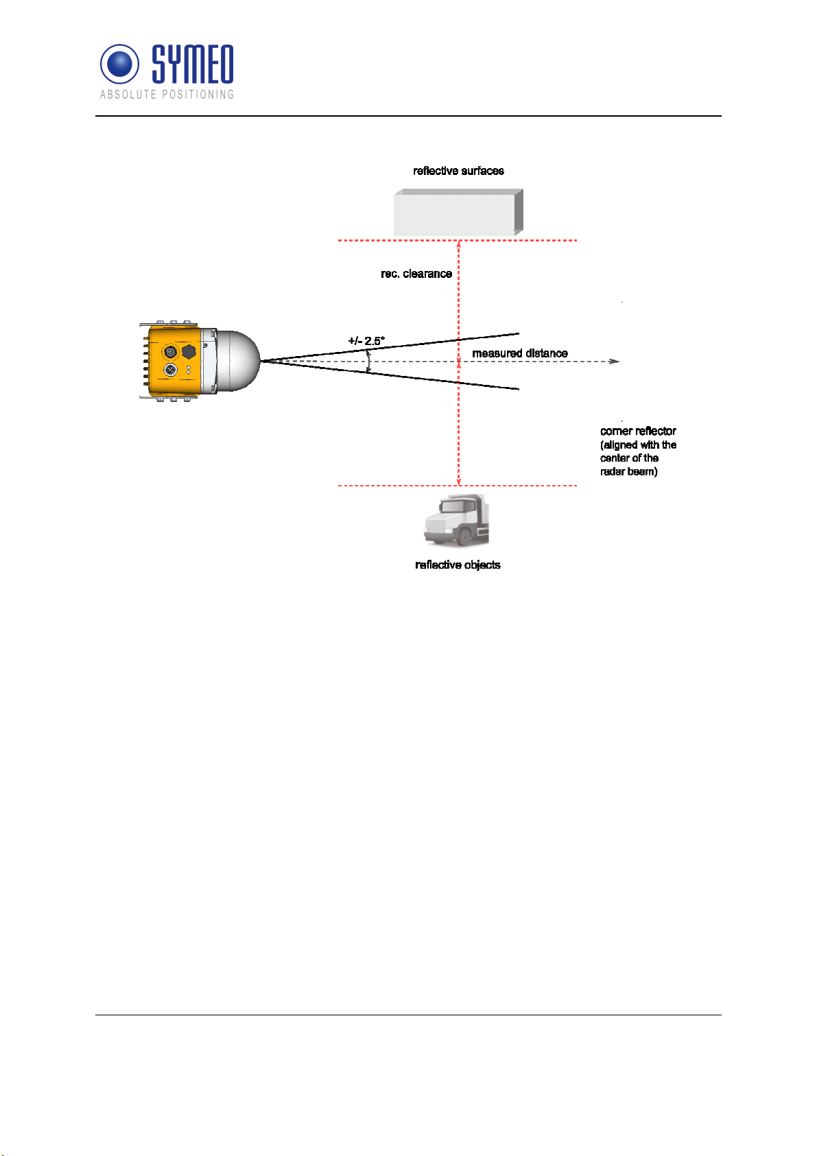
3.4.1 Primary Radar Mode
In primary radar mode, a single radar measures the distance and speed to a reflective object
/ target, typically a metal corner reflector. The following features differentiate the primary
radar mode from the other radar modes:
Suitable for ranges up to 50 m
Range depends on target radar cross section (RCS)
Very high update rate (up to 350 Hz)
Cost effective installation with a single radar
Distance measurements to passive objects enable additional applications for primary radar
mode,:
Presence / absence check (e.g. in a radar barrier)
Profile / measurement (e.g. of bulk material)
Detection of arbitrary objects (e.g. of personell or vehicles)
Figure 3.3 shows the typical setup of a LPR®-1DHP-220-R radar and a corner reflector for a
primary radar distance measurement.
Radar Basics
Copyright © Symeo GmbH 2018
DOC.EDO.000341.WORK.EN_LPR-1DHP-200_Product-Documentation.docx
Page 10 of 71
SYMEO Local Positioning Radar System
Product Family LPR®-1DHP-200 – Product Documentation
Figure 3.3: Primary radar mode measurement setup
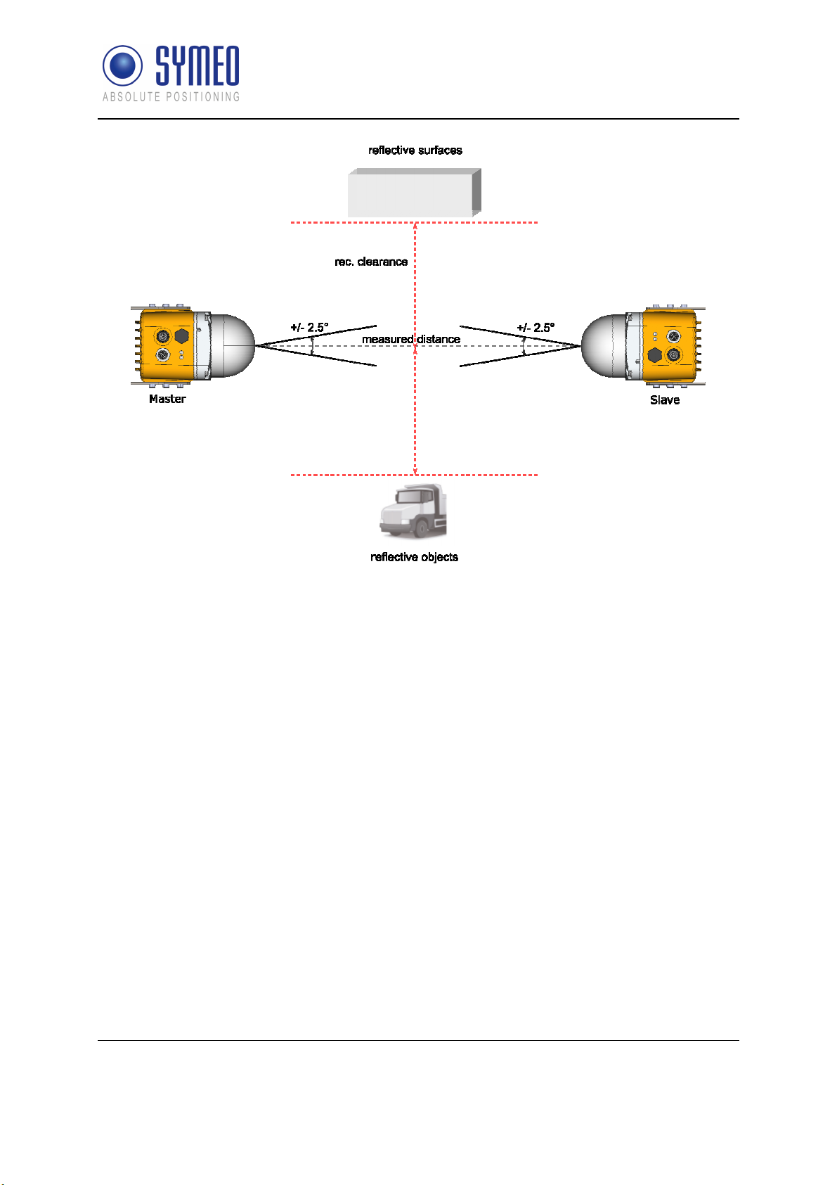
3.4.2 Secondary Radar Mode
In secondary radar mode two radars measure the distance and speed between each other.
The following features differentiate the secondary radar mode from the other radar modes:
Suitable for ranges up to 300 m
Distance is always measured to the partner unit and not to passive objects
Figure 3.4 shows the typical setup of two LPR®-1DHP-260 radars for a secondary radar
range measurement.
Radar Basics
Copyright © Symeo GmbH 2018
DOC.EDO.000341.WORK.EN_LPR-1DHP-200_Product-Documentation.docx
Page 11 of 71
SYMEO Local Positioning Radar System
Product Family LPR®-1DHP-200 – Product Documentation
Figure 3.4: Secondary radar mode measurement setup
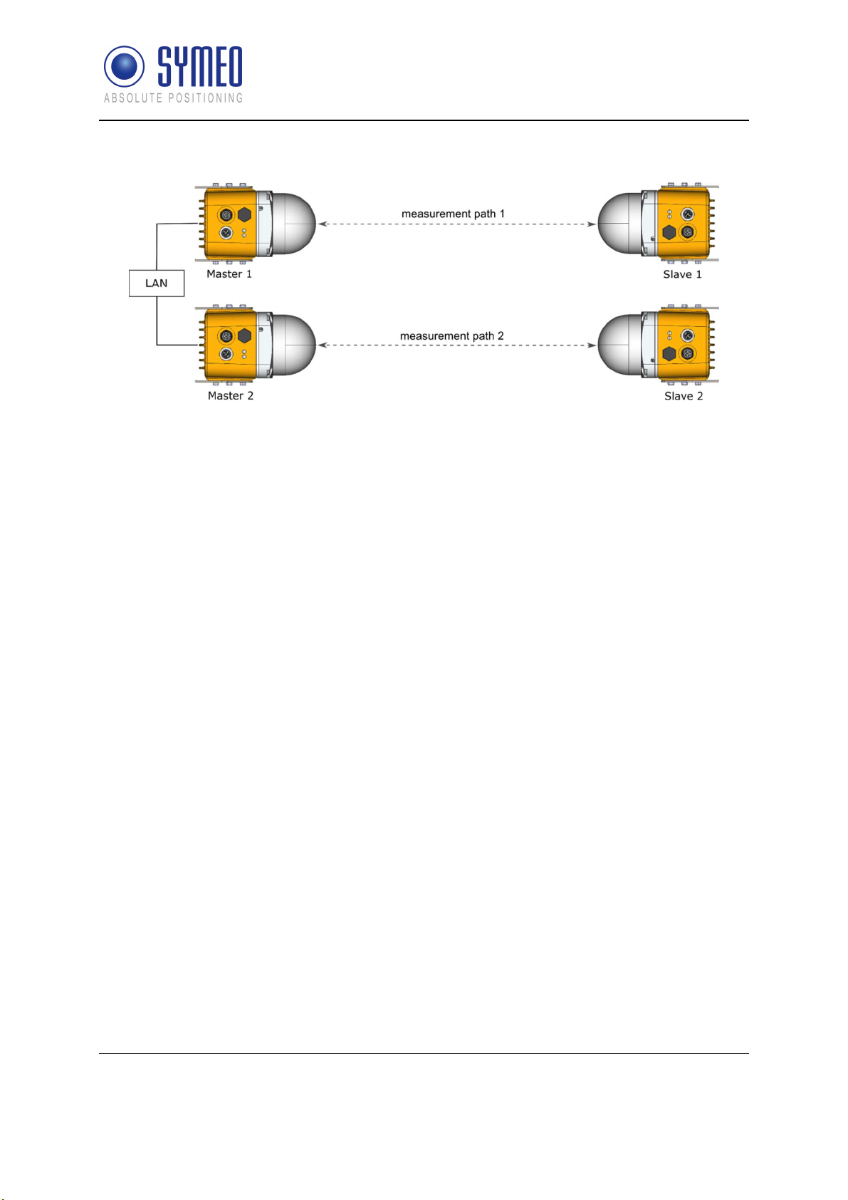
3.4.3 Diversity Radar Mode
In diversity radar mode four radar units are grouped into two pairs, which are mounted in a
way that two secondary range measurements are performed side by side separated by a
defined distance. The following features differentiate the diversity radar mode from the other
radar modes:
Suitable for ranges up to 500 m
Distance is always measured to the partner unit and not to passive objects
No clearance to reflective surfaces / objects required (see chapter 5.1; Fresnel zone still
needs to be free of obstacles)
If one of the two measurement paths fails, the system falls back to operation in
secondary radar mode and is therefore still available (error is indicated in diversity status
byte)
Figure 3.5 shows the typical setup of four LPR®-1DHP-281 radars for a diversity radar range
measurement.
Radar Basics
Copyright © Symeo GmbH 2018
DOC.EDO.000341.WORK.EN_LPR-1DHP-200_Product-Documentation.docx
Page 12 of 71
SYMEO Local Positioning Radar System
Product Family LPR®-1DHP-200 – Product Documentation
Figure 3.5: Diversity radar mode measurement setup
3.5 Bandwidth Modes
The LPR®-1DHP-200 is able to operate in the 57 - 64 GHz band. Depending on your used
region and regulatory authority setting, a limited number of bandwidth modes are available
for selection in the WebUI.
The selected bandwidth modes have impact on the accuracy, resolution and range of the
radar. The dependency of performance and bandwidth mode with respect to regional
restrictions is depicted in chapter 10. It is recommended to use the 0.5 GHz or 2 GHz
bandwidth mode for standard applications.
Within a single bandwidth mode, multiple sync channels are available. For each channel
block, the effective bandwidth of a sync channel reduces with increasing sync channel
number.
3.6 Accuracy
To maximize the accuracy of a LPR®-1DHP-200 measurement setup, different error sources
which influence the accuracy need to be taken into account:
Mounting position
o
Adhere to the mounting instructions (see chapter 5) to minimize systematic errors
(e.g. horizontal or vertical offset and alignment).
Reflective surfaces and objects
o
Reflections of the radar signal, e.g. from walls, can cause distance errors in primary
and secondary radar mode which vary with the measured distance. Ensure the
recommended clearance to surfaces and objects described in chapter 5.1 or use
diversity radar mode to minimize errors caused by reflections.
Measurement noise
o
Measurement noise caused by the radar itself is the lower limit to the overall
accuracy. The noise will decrease with increasing bandwidth. For primary radar
mode, noise will increase with range and decrease with target radar cross section
Radar Basics
Copyright © Symeo GmbH 2018
DOC.EDO.000341.WORK.EN_LPR-1DHP-200_Product-Documentation.docx
Page 13 of 71

SYMEO Local Positioning Radar System
Product Family LPR®-1DHP-200 – Product Documentation
(dependent on target size, shape and material). In secondary radar mode noise is
constant within the specified range and will increase for ranges above.
Temperature drift
o
Changes in device and air temperature can lead to measurement offsets of approx.
+/-10mm. These errors vary slowly with time and can be countered by ensuring
constant environmental conditions, running a warm up phase of 30 minutes before
operation or by using a calibration reference.
3.7 Range
To maximize the range of a LPR®-1DHP-200 measurement setup the following aspects have
to be taken into account:
Mounting position
o
Adhere to the mounting instructions (see chapter 5). Ensure minimum alignment error
and vertical / horizontal offset and equal orientation (for secondary and diversity radar
mode)
Fresnel zone
o
Ensure the Fresnel zone is free of absorbing or reflecting objects
Reflective surfaces and objects
o
Reflections of the radar signal, e.g. from walls, can lead to a reduction of the received
signal strength and hence maximum range. Ensure the recommended clearance to
surfaces and objects described in chapter 5.1 or use diversity radar mode to counter
the effects caused by reflections
Target RCS (only primary radar mode)
o
In primary radar mode the maximum range depends on the target RCS (radar cross
section) which is a function of target size, material and shape. If the maximum range
is required use targets with a high RCS (e.g. the corner reflector MTE000958)
VGA value
o
For maximum range set the “VGA value” to the highest possible value that is allowed
in you regulatory domain. The WebUI will use your region settings to limit the “VGA
value” and hence range is reduced in certain regions (see chapter 10).
The minimum range of the sensors can be reduced to values below the specified minimum
distance by adapting the “VGA value”, the “RX attenuator” and the threshold settings (for
primary radar). This however affects the maximum range and the accuracy of the radar and
shall therefore only be applied by trained personell.
Radar Basics
Copyright © Symeo GmbH 2018
DOC.EDO.000341.WORK.EN_LPR-1DHP-200_Product-Documentation.docx
Page 14 of 71

SYMEO Local Positioning Radar System
Product Family LPR®-1DHP-200 – Product Documentation
4 Components
4.1 Device Overview
The LPR®-1DHP-200 consists of the following parts (see Figure 4.1 and Figure 4.2):
Dielectric Lens (A1)
o
focuses the radar beam
Metal gland (A2)
o
fixes the lens to the housing with four screws
o
seals the device against water and dirt
o
holds the inner parts of the device in place
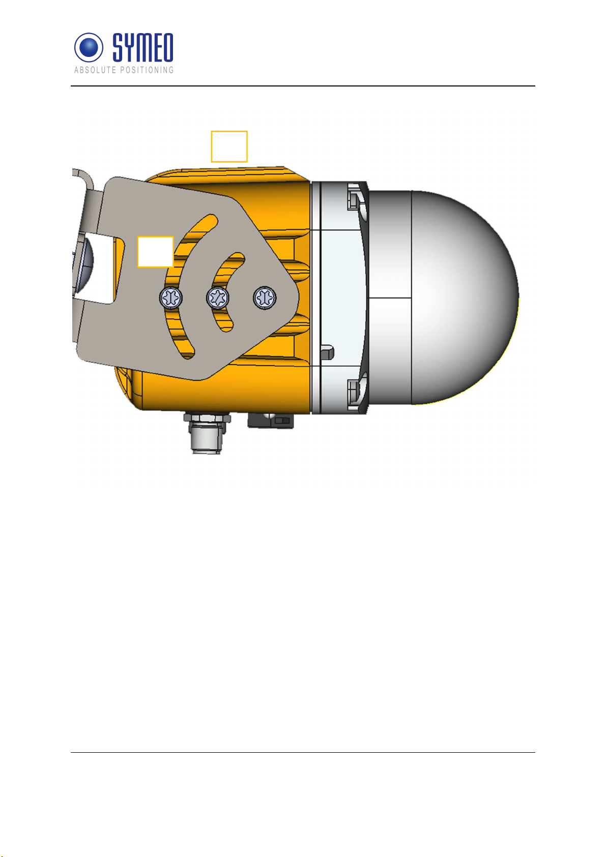
Housing (A3)
o
provides LEDs (B1) and a pressure equalization membrane (B2)
o
provides the M12 power supply connector (C1) and the M12 Ethernet connector (C2)
o
provides 2 x 3 M6 screwing holes (B3) for mounting in the mounting bracket
o
provides an adjustment guide for usage with a laser level for exact radar beam
alignment (B4)
o
ensures IP65 protection class and heat dissipation
The housing must not be opened.
Components
Copyright © Symeo GmbH 2018
DOC.EDO.000341.WORK.EN_LPR-1DHP-200_Product-Documentation.docx
Page 15 of 71

SYMEO Local Positioning Radar System
Product Family LPR®-1DHP-200 – Product Documentation
A1
A2
B3
B2
A3
Figure 4.1: Front view of the LPR®-1DHP-200
C2
C1
B1
B3
Components
Copyright © Symeo GmbH 2018
DOC.EDO.000341.WORK.EN_LPR-1DHP-200_Product-Documentation.docx
Page 16 of 71
SYMEO Local Positioning Radar System
Product Family LPR®-1DHP-200 – Product Documentation
B4
B3
Figure 4.2: Side view of the LPR®-1DHP-200
Components
Copyright © Symeo GmbH 2018
DOC.EDO.000341.WORK.EN_LPR-1DHP-200_Product-Documentation.docx
Page 17 of 71
SYMEO Local Positioning Radar System
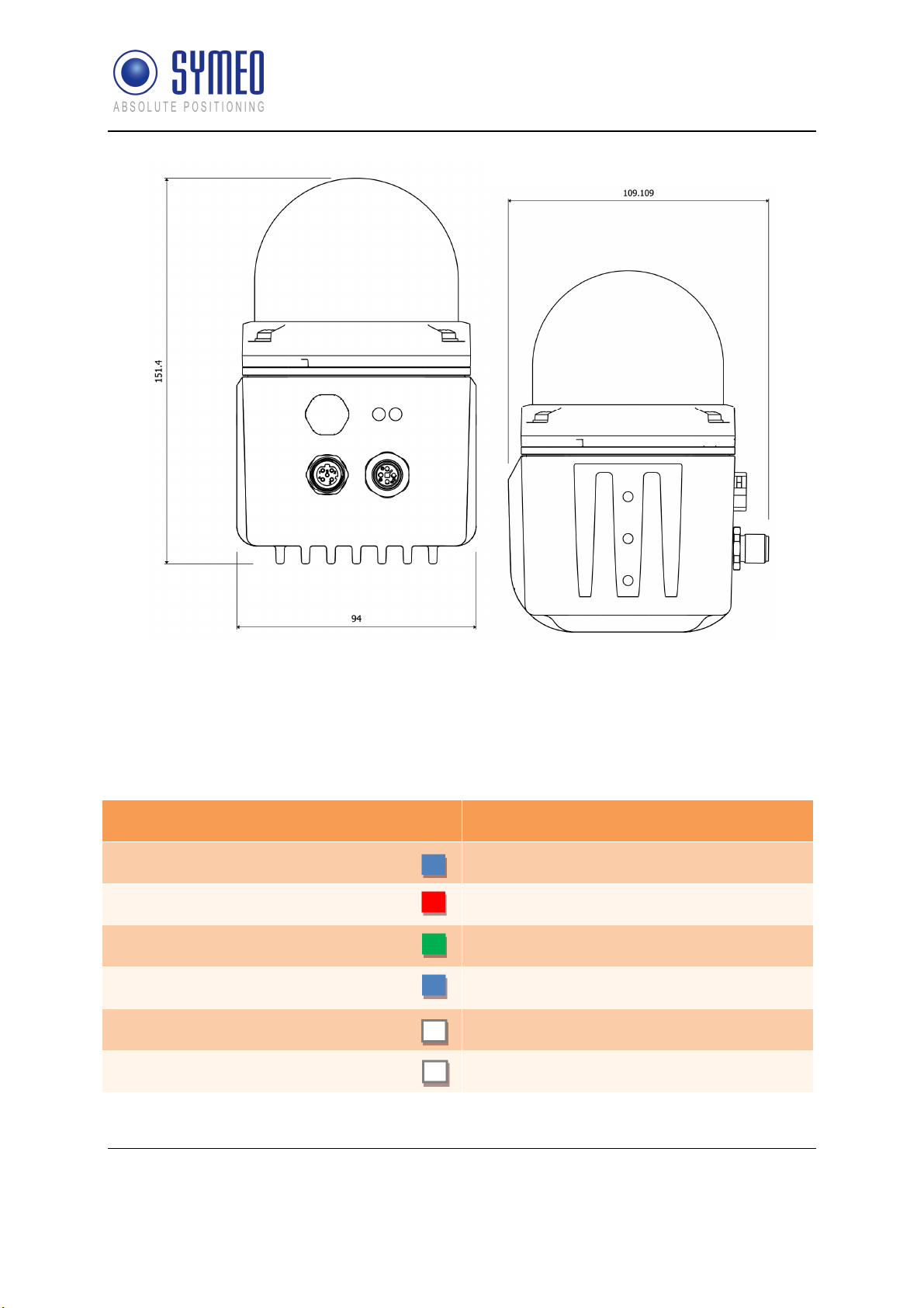
Product Family LPR®-1DHP-200 – Product Documentation
Figure 4.3: LPR®-1DHP-200 housing dimensions
4.2 LED Display
The LEDs (Status LED on the left and Ethernet LED on the right) indicate the different states
of the device (see Table 4.1).
LED Indication Status of the Device
Status LED lights up BLUE Device is booting up
Status LED lights up RED Invalid measurement
Status LED lights up GREEN Valid measurement
Status LED flashes BLUE Firmware update in progress
Ethernet LED lights up WHITE Ethernet interface established
Ethernet LED flashes WHITE Ethernet interface transmits data
Table 4.1: LED Display
Components
Copyright © Symeo GmbH 2018
DOC.EDO.000341.WORK.EN_LPR-1DHP-200_Product-Documentation.docx
Page 18 of 71
SYMEO Local Positioning Radar System
Product Family LPR®-1DHP-200 – Product Documentation
4.3 Connectors
The housing of the LPR®-1DHP-200 provides the following M12 connectors (see Figure 4.1
and Figure 4.2):
Power supply input (C1)
Ethernet connector (C2) for network connection
The necessary connectors for manufacturing cables that fit your installation and cable length
are available from symeo and are described in the following chapters.
4.3.1 Power Supply
The LPR®-1DHP-200 is powered by a 4-pin M12-Connector.
Plugs
Recommended connector:
SACC-M12FST-4PECON-PG 9-M – 1418052 (obsolete)
SACC-M12FST-4CON-PG 9-M - 1418052
o Cable diameter: 6 - 8 mm
Tightening torque: 0.4 Nm
o Symeo order number: MTE101761
The connector is also part of the following M12 connector set:
M12 connector set (Ethernet + Power supply)
o Symeo order number: MTE102366
Figure 4.4: M12 power supply connector
Components
Copyright © Symeo GmbH 2018
DOC.EDO.000341.WORK.EN_LPR-1DHP-200_Product-Documentation.docx
Page 19 of 71
SYMEO Local Positioning Radar System
Product Family LPR®-1DHP-200 – Product Documentation
Pin Assignment
Power Supply 11 V DC – 36 V DC M12 Connector
VDC+ Pin 1
VDC+ Pin 2 (bridged to Pin 1)
VDC- Pin 3
VDC- Pin 4 (bridged to Pin 3)
Table 4.2: Pin assignment power supply
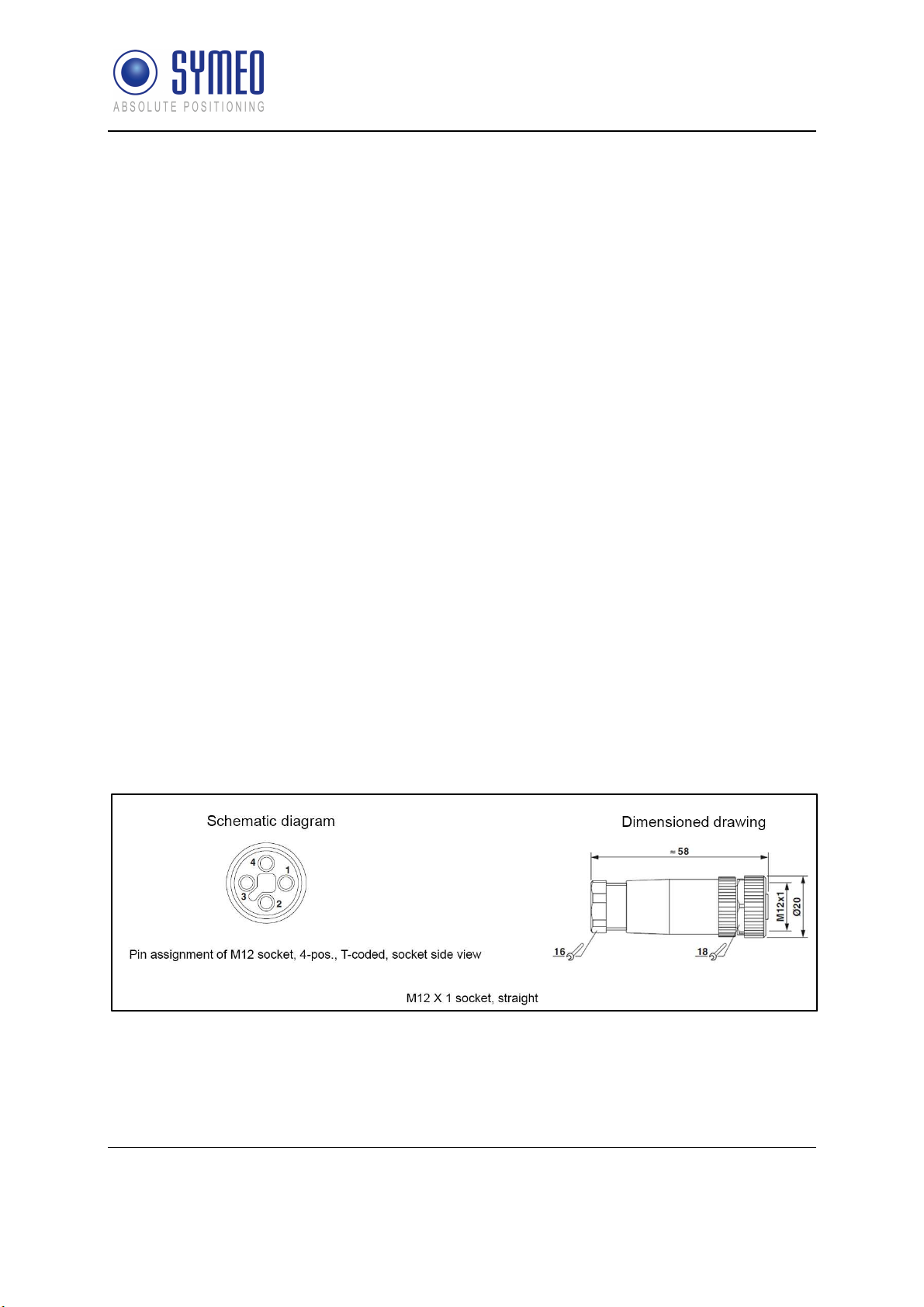
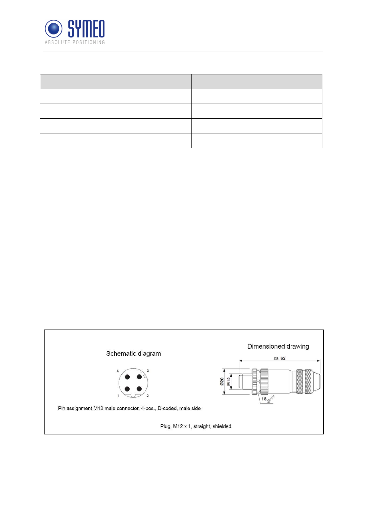
4.3.2 Ethernet M12
The LPR®-1DHP-200 can be connected to a LAN or a Profinet bus system (Production Code
"n" required) via an M12 Ethernet Connector.
Plugs
Recommended connector:
SACC-M12MSD-4CON-PG 7-SH – 1521258
o Cable diameter: 4 – 6 mm (PG7)
Tightening torque: 0.4 Nm
o Symeo order number: MTE101768
o
The connector is also part of the following M12 connector set:
M12 connector set (Ethernet + Power supply)
o Symeo order number: MTE102366
Figure 4.5: M12 Ethernet connector
Components
Copyright © Symeo GmbH 2018
DOC.EDO.000341.WORK.EN_LPR-1DHP-200_Product-Documentation.docx
Page 20 of 71
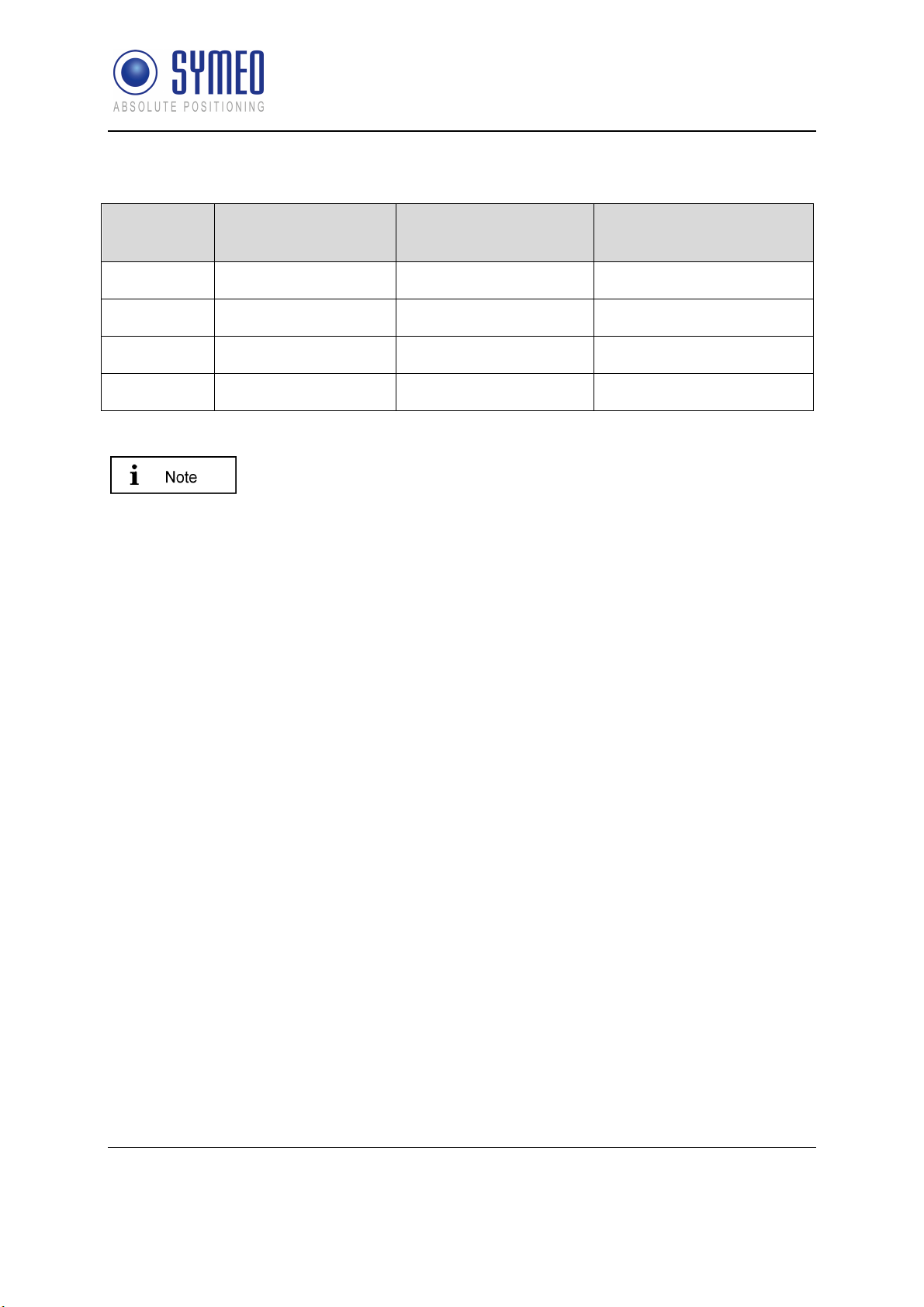
Pin Assignment
SYMEO Local Positioning Radar System
Product Family LPR®-1DHP-200 – Product Documentation
Signal Color of Wire
PROFInet®
TD+ Yellow White/Orange 1
TD- Orange Orange 3
RD+ White White/Green 2
RD- Blue Green 4
Table 4.3: Pin assignment for Ethernet M12
Color of Wire
EIA/TIA 568B
Pin Assignment
If the Ethernet connecter is left unused, install the protective cap of the
connector.
Connector Cable M12 – RJ45
A connector cable M12 – RJ45 (2m) for connecting the radar to a PC for initial
commissioning and configuration is available from Symeo:
Symeo order number: MTE102007
4.4 Mounting Brackets
4.4.1 Mounting Bracket – MTM102513
For mounting the LPR®-1DHP-200 to a pipe, a mounting bracket is available from Symeo.
The pipe diameter should measure between 40 and 75 mm.
Components
Copyright © Symeo GmbH 2018
DOC.EDO.000341.WORK.EN_LPR-1DHP-200_Product-Documentation.docx
Page 21 of 71

SYMEO Local Positioning Radar System
Product Family LPR®-1DHP-200 – Product Documentation
Figure 4.6: LPR®-1DHP-200 mounted to a pipe with the mounting bracket.
Figure 4.7: MTM102513 dimensions.
Adhere to the following tightening torques for mounting:
LPR®-1DHP-200 to mounting bracket (6x M5 screws): 4Nm
Tube clamp (2x M8 screws): 8Nm
Components
Copyright © Symeo GmbH 2018
DOC.EDO.000341.WORK.EN_LPR-1DHP-200_Product-Documentation.docx
Page 22 of 71

SYMEO Local Positioning Radar System
Product Family LPR®-1DHP-200 – Product Documentation
4.4.2 Diversity Mounting Bracket – MTM102512
For mounting two LPR®-1DHP-200 for operation in the diversity radar mode a diversity
mounting bracket is available from Symeo.
Figure 4.8: Two LPR®-1DHP-200 mounted in the diversity mounting bracket.
Adhere to the following tightening torques for mounting:
LPR®-1DHP-200 to mounting bracket (2x 6x M5 screws): 4Nm
Tube clamp (2x M8 screws): 8Nm
4.5 Corner Reflectors
For operation in the primary radar mode different types of corner reflectors used as targets
for the distance measurement are available from Symeo.
4.5.1 Corner reflector 500mm – MTE000958
Corner reflector with edge length 500mm for maximum range.
Figure 4.9: Corner reflector 500mm.
Components
Copyright © Symeo GmbH 2018
DOC.EDO.000341.WORK.EN_LPR-1DHP-200_Product-Documentation.docx
Page 23 of 71

SYMEO Local Positioning Radar System
Product Family LPR®-1DHP-200 – Product Documentation
4.5.2 Corner reflector 250mm – MTE001011
Corner reflector with edge length 250mm. Range is reduced to approx. 70% compared to
MTE000958.
Figure 4.10: Corner reflector 250mm.
4.5.3 Mount for corner reflector – MTM000169
For mounting the corner reflector, a pipe mounting bracket is available from Symeo. The pipe
diameter should be between 40 and 75 mm.
Components
Copyright © Symeo GmbH 2018
DOC.EDO.000341.WORK.EN_LPR-1DHP-200_Product-Documentation.docx
Page 24 of 71

SYMEO Local Positioning Radar System
Product Family LPR®-1DHP-200 – Product Documentation
5 Mounting
5.1 General Mounting Instructions
Site-specific mounting instructions must be followed if available.
The more accurately the radar units and reflectors are aligned to each other, the better
the performance of the measurement setup will be in terms of accuracy and range.
The radar units and/or corner reflectors must move parallel to the radar beam in the
installation.
Ensure that the Fresnel Zone is free of obstacles.
Ensure that your measured distances lie in the specified measuring range (see chapter
10)
For primary and secondary radar mode (not for diversity radar mode) ensure that
reflective surfaces (e.g. walls, the roof, the floor, crane tracks) and other reflective objects
(e.g. poles, tubes, bridges, vehicles) have the recommended clearance to the center of
the radar beam that is in accordance with
Figure 3.3 and Figure 3.4).
Measuring
distance d in m
Recommended
clearance in m
Table 5.1: Recommended clearance to reflective surfaces and objects.
10 20 30 50 70 100 150 200 250 300
0.2 0.5 0.7 1.1 1.6 2.2 3.3 4.4 5.5 6.6
Table 5.1 (see also
5.2 Mounting for Primary Radar Mode
The Primary Radar Mode is available for Product Types LPR®-1DHP220-R and LPR®-1DHP-290.
Mounting
Copyright © Symeo GmbH 2018
DOC.EDO.000341.WORK.EN_LPR-1DHP-200_Product-Documentation.docx
Page 25 of 71

SYMEO Local Positioning Radar System
Product Family LPR®-1DHP-200 – Product Documentation
For a primary radar distance measurement, typically a single radar unit and a recommended
corner reflector are mounted facing each other.
For operation in the primary radar mode the following issues must be considered:
The radar and the corner reflector must be installed in a way that the center of the corner
reflector is aligned with the center of the radar beam.
The reflector has to be either the nearest (first) target or the strongest target to be
detected properly.
Radar and radar reflector must be aligned to each other with maximum accuracy (at least
+/- 2,5°).
Minimum horizontal and vertical offset between radar and reflector must be ensured.
Follow the subsequent steps for proper installation of radar unit and reflector:
Mount a standard mounting bracket on one side of your measurement setup.
Mount the radar into the mounting bracket.
Mount a corner reflector to the other side of your measurement setup.
Mount the corner reflector in a way, that the opening faces the radar. The 3 corners of the
corner reflector opening must have equal distance to the radar.
Carefully align the radar to the corner cube reflector. To do so, it is recommended to use
a laser level fitted into the alignment aid, which should point at the reflector.
Fix the system by tightening the screws of the mounting bracket and the pipe clamp with
the correct tightening torques.
Connect the power supply and Ethernet cable with M12 connectors as specified in
chapter 4.3.1 and 4.3.2.
5.3 Mounting for Secondary Radar Mode
The Secondary Radar Mode is available for Product Types LPR®1DHP-260 and LPR®-1DHP-290.
For a secondary radar distance measurement, two radar units, one configured as a “master”
and one as a “slave” are mounted facing each other in a way, that the center of the emitted
radar beam of each unit hits the other unit. The master unit initiates the measurement while
the slave unit replies.
For operation in the secondary radar mode the following issues must be considered:
The two radar units must be installed in a way, that the center of the emitted radar beam
of each unit hits the other unit.
The two radar units must be oriented exactly equally or turned by 180° along the radar
beam axis (e.g. connectors of both devices facing downwards).
Minimum horizontal and vertical offset between both radar units must be ensured.
Both radar units must be aligned to each other with maximum accuracy (at least +/- 2,5°).
Mounting
Copyright © Symeo GmbH 2018
DOC.EDO.000341.WORK.EN_LPR-1DHP-200_Product-Documentation.docx
Page 26 of 71

SYMEO Local Positioning Radar System
Product Family LPR®-1DHP-200 – Product Documentation
Follow the subsequent steps for proper installation of the radar units:
Mount a standard mounting bracket to one side of the measurement setup.
Mount the radar unit into the mounting bracket.
Repeat the first two steps on the other side of the measurement setup.
Carefully align both radar units to each other. To do so, it is recommended to use a laser
level fitted into the alignment aids. The laser dot should point to the other sensor for both
directions (Master -> Slave, Slave -> Master).
Fix the systems by tightening the screws of the mounting brackets and the pipe clamps
with the correct tightening torques.
Connect the power supply and Ethernet cable with the M12 connectors as specified in
chapter 4.3.1 and 4.3.2 to both stations. The Ethernet connection at the Slave unit is only
required for configuration and can be removed during operation. If removed install the
protective cap of the connector.
6 Quick Setup
This chapter gives a short introduction for the setup of the radar sensors with the help of the
WebUI. For detailed information on all possible settings, please refer to chapter 8.
6.1 Initial Setup
The following steps must be followed for the initial setup of all radar units:
Mount and align the radar units as outlined in chapter 5.
Connect the radar units to a power source (11 – 36V) and wait until booting is finished
(blue LED switches to red or green).
Connect the radar unit to a PC via Ethernet and open the Webinterface (WebUI) in a
Webbrowser (http://192.168.1.99). See chapter 7 for a detailed description.
Sign in to the WebUI (see chapter 8.2).
Choose country and regulatory authority.
6.2 Quick Setup for Primary Radar Mode
The following settings must be set in the WebUI for operation in primary radar mode:
Device -> Settings -> Measurement basics
o
Station mode = Primary
o
Bandwidth mode = Choose a bandwidth that fits your required range and accuracy
o
Channel block = Use recommended selection
o
Sync channel = different than any other LPR®-1DHP-200 sensor in range; for
neighboring measurement paths use only every fourth sync channel.
Quick Setup
Copyright © Symeo GmbH 2018
DOC.EDO.000341.WORK.EN_LPR-1DHP-200_Product-Documentation.docx
Page 27 of 71

SYMEO Local Positioning Radar System
Product Family LPR®-1DHP-200 – Product Documentation
Device -> Settings -> Measurement details
o
Target search mode = “First” if the reflector is the first target in range, “Strongest” if
the reflector is the strongest target in range.
The setting “Target search mode” highly impacts the behavior of the radar,
especially in multi target environments (see Figure 8.16). “First target” may
lead to distance measurements to unintended targets in the vicinity of the
radar (e.g. a person passing the radar beam). “Strongest target” may lead
to distance measurements to unintended targets present in the
background of your intended target (e.g. a wall behind a corner reflector).
Perform therefore always a test as described in chapter 6.4 to verify this
setting.
Review and Calibrate your measurement as stated in chapter 6.4.
6.3 Quick Setup for Secondary Radar Mode
The following settings must be set in the WebUI of the master and slave sensor for operation
in secondary radar mode.
Only the Master unit outputs range data.
Master
Device -> Settings -> Measurement basics
o
Station mode = Master
o
Bandwidth mode = Choose a bandwidth that fits your required range and accuracy
o
Channel block = Use recommended selection
o
Sync channel = different than any other LPR®-1DHP-200 sensor in range (except the
related Slave); for neighboring measurement paths use only every fourth sync
channel.
Slave
Device -> Settings -> Measurement basics
o
Station mode = Slave
o
Bandwidth mode = same as Master
o
Channel block = same as Master
o
Sync channel = same as Master
Review and Calibrate your measurement as stated in chapter 6.4.
6.4 Review and Calibration of the Measurement Setup
Diagnostics -> Range measurement statistics -> Live range measurement
Quick Setup
Copyright © Symeo GmbH 2018
DOC.EDO.000341.WORK.EN_LPR-1DHP-200_Product-Documentation.docx
Page 28 of 71

SYMEO Local Positioning Radar System
Product Family LPR®-1DHP-200 – Product Documentation
o
Run a warm up phase of 30 minutes before calibration.
o
Compare the “current distance” to the actual distance in your measurement setup for
all ranges.
o
The mean value of the difference between the actual distance and the measured
distance is the reference-offset value, which needs to be added to the current
distance to match the radar’s and installation’s coordinate systems. The radar
therefore offers the setting “Measurements Details -> Customer specific offset”.
o
Make sure that the maximum and standard deviation of the difference between the
offset corrected measured and actual distance meets your accuracy requirements for
all possible distances in your measurement setup.
The LPR®-1DHP-200 are delivered with the fixed TCP/IP IP-Address
192.168.1.99.
7 Establishing a TCP/IP Connection
For configuration of the radar units, a TCP/IP connection has to be set up. Make sure that:
The unit is running.
The radar unit is connected with an appropriate Ethernet cable to a PC or a similar
device, which has a web browser installed.
The radar and the PC are located in the same subnet of the TCP/IP network. That means
that the first three numbers of the radar’s and PC’s IP-addresses must be equal.
No firewall is blocking the communication between PC and radar.
If PC and radar are not located in the same subnet open the TCP/IP network settings of your
network adapter in your operating system. Enter a fixed IP-Address e.g. 192.168.1.1 and the
subnet mask 255.255.255.0.
Establishing a TCP/IP Connection
Copyright © Symeo GmbH 2018
DOC.EDO.000341.WORK.EN_LPR-1DHP-200_Product-Documentation.docx
Page 29 of 71

SYMEO Local Positioning Radar System
Product Family LPR®-1DHP-200 – Product Documentation
Figure 7.1: Network Settings under Microsoft Windows
The LPR®-unit should be available via your PC now. You can check the connection with a
ping to the LPR®-1DHP-200 unit:
1. Push the Windows Start Button
2. Choose Run (Skip under Windows 10)
3. Enter cmd and confirm
4. Enter: ping 192.168.1.99 or the IP-address of the LPR®-1DHP-200 unit in the cmd.exe
window and confirm
The LPR®-1DHP-200 should answer with a Reply.
Figure 7.2: Ping LPR®-1DHP-200 Unit
For detection of all Symeo devices located in your network (useful if the IP-Address of a
radar unit is unknown), you can download the tool Symeo IP Discover in the Partner Login
under www.symeo.com.
Establishing a TCP/IP Connection
Copyright © Symeo GmbH 2018
DOC.EDO.000341.WORK.EN_LPR-1DHP-200_Product-Documentation.docx
Page 30 of 71

SYMEO Local Positioning Radar System
Product Family LPR®-1DHP-200 – Product Documentation
8 Device Setup via the Web User Interface
The Web User Interface allows you to change all settings, perform firmware updates, view
system status and diagnostic information and much more.
8.1 Open the Web User Interface
A TCP/IP Connection is required.
Open your web browser. In the address bar of the web browser, enter the IP address of
the LPR®-1DHP-200: e.g. http://192.168.1.99.
The welcome page for the LPR®-1DHP-200 WebUI should appear.
A language selection can be made using the flags in the top right corner of the interface.
Device Setup via the Web User Interface
Copyright © Symeo GmbH 2018
DOC.EDO.000341.WORK.EN_LPR-1DHP-200_Product-Documentation.docx
Page 31 of 71

SYMEO Local Positioning Radar System
Product Family LPR®-1DHP-200 – Product Documentation
Figure 8.1: Open Web User Interface
Device Setup via the Web User Interface
Copyright © Symeo GmbH 2018
DOC.EDO.000341.WORK.EN_LPR-1DHP-200_Product-Documentation.docx
Page 32 of 71

SYMEO Local Positioning Radar System
Product Family LPR®-1DHP-200 – Product Documentation
8.2 Sign In
In order to be able to change settings a sign in to the WebUI is necessary. Press therefore
“Sign In” in the upper right corner of the WebUI. You will be prompted to enter your
information for authentication. The dialog box with the username and password field will
appear (see Figure 8.2).
Figure 8.2: WebUI Login
Enter the user name "symeo" and the password "54all2u" and press "Login". Now your
status is displayed as "Logged in".
8.3 Initial Operation
When the WebUI is opened for the first time or after a software reset, the note “Environment
uninitialized” will appear (see Figure 8.1).
During the initial operation, you need to configure the operating country, in
which you want to use this unit. This is necessary to abide to the radio
signal restrictions enforced by the local authorities. Your selection will
have impact on the selectable Bandwidth Modes as well as on the
maximum transmit power and hence range of the radar unit.
Since this is a mandatory setting, all functionality of this device will remain
disabled, until the country setting has been successfully configured.
Click the “Configure environment” button to configure the working environment.
Device Setup via the Web User Interface
Copyright © Symeo GmbH 2018
DOC.EDO.000341.WORK.EN_LPR-1DHP-200_Product-Documentation.docx
Page 33 of 71

SYMEO Local Positioning Radar System
Product Family LPR®-1DHP-200 – Product Documentation
Figure 8.3: Initial setup of environment of the LPR®-1DHP-200
Select your country to determine the operating environment and confirm it with the “Save”
button (see
Figure 8.3
).
The setting has to be the same on all Symeo devices used in a specific country.
Now activate the settings by clicking the "Activate changes" button (see Figure 8.4).
Figure 8.4: Initial setup of environment - Activate changes
The following window appears:
Device Setup via the Web User Interface
Copyright © Symeo GmbH 2018
DOC.EDO.000341.WORK.EN_LPR-1DHP-200_Product-Documentation.docx
Page 34 of 71

SYMEO Local Positioning Radar System
Product Family LPR®-1DHP-200 – Product Documentation
Figure 8.5: Initial setup of environment - Amend invalid settings
In the top left corner, a red frame appears which indicates that for a functioning measuring
distance, the measurement values, which have not yet been set or which are invalid, are still
to be processed.
Click the “Amend invalid settings” button.
Figure 8.6: Settings window for mandatory values
You will be automatically guided to the settings menu sub-item “Measurement basics”, where
strictly necessary parameters must be set. For further information about these mandatory
settings please refer to the chapter “Device - Settings – Measurement Basics
Device Setup via the Web User Interface
Copyright © Symeo GmbH 2018
DOC.EDO.000341.WORK.EN_LPR-1DHP-200_Product-Documentation.docx
Page 35 of 71

SYMEO Local Positioning Radar System
Product Family LPR®-1DHP-200 – Product Documentation
If you have entered all these settings, click the “Submit Changes” button.
Figure 8.7: Change of mandatory values
8.4 Change Settings, Review and Save Changes
Upon pressing the “Submit Changes” button in any settings sub item, the WebUI is updated
and the choice of valid settings is adapted to your made changes. The settings will however
not be applied to the radar until you “Save all changes” in the the “Review changes” page or
in the top left corner of this page.
You can review your changes by clicking the “Review changes” button in the top left
corner of the homepage or at the bottom of the screen (see Figure 8.8).
Device Setup via the Web User Interface
Copyright © Symeo GmbH 2018
DOC.EDO.000341.WORK.EN_LPR-1DHP-200_Product-Documentation.docx
Page 36 of 71

SYMEO Local Positioning Radar System
Product Family LPR®-1DHP-200 – Product Documentation
Figure 8.8: Save or discard all changes
Confirm the changes by clicking the “Save all changes” button. The dialog box “Changes
have been applied” will appear (see
Figure 8.9
).
If you would like to discard all changes made after the last save, press “Discard all changes”.
After saving, it takes several seconds until the measurement is restartet with the new
settings. Some settings additionally require a reboot of the radar.
Figure 8.9: Changes have been saved
Device Setup via the Web User Interface
Copyright © Symeo GmbH 2018
DOC.EDO.000341.WORK.EN_LPR-1DHP-200_Product-Documentation.docx
Page 37 of 71

SYMEO Local Positioning Radar System
Product Family LPR®-1DHP-200 – Product Documentation
8.5 Home Page
On the home page (see Figure 8.10), important information about the LPR®-1DHP-200 is
displayed.
You can always return to the start page if you press on the Symeo symbol in the top
left hand corner of this page.
Figure 8.10: The home page of the LPR®-1DHP-200
On top of every page, the device status is shown (see
Figure 8.11
):
Figure 8.11: WebUI - Device Status
The “Device Status” window shows the status of the Services, of the Interfaces and the
Remote Access status.
Device Setup via the Web User Interface
Copyright © Symeo GmbH 2018
DOC.EDO.000341.WORK.EN_LPR-1DHP-200_Product-Documentation.docx
Page 38 of 71

SYMEO Local Positioning Radar System
Product Family LPR®-1DHP-200 – Product Documentation
The service status “Distance measurement” is green, if the measurement is setup
correctly.
This also applies to the Remote Access Option if it is available, configured and
connected.
The interface status “Binary protocol” button turns green if a client is successfully
connected to the customer port.
The “Information overview” window (see Figure 8.12) shows:
Hostname of the LPR®-1DHP-200 unit
IP-address
Application version
Mode: Primary, Master or Slave
System time
Figure 8.12: WebUI Information overview
The “Product properties” window displays:
Model number
Product name
Serial number
Unit production code
o
States the available and active performance features of the purchased product (see
Figure 8.13).
Figure 8.13: WebUI - Product properties
Click the “Unit production code” button under the menu item “Product properties” (see
Figure 8.13). The table with the product features will be displayed.
Device Setup via the Web User Interface
Copyright © Symeo GmbH 2018
DOC.EDO.000341.WORK.EN_LPR-1DHP-200_Product-Documentation.docx
Page 39 of 71

SYMEO Local Positioning Radar System
Product Family LPR®-1DHP-200 – Product Documentation
The table below shows a complete list of all features available for this unit (see Figure 8.14).
Figure 8.14: WebUI - Product features
Not all product features can be combined with each other.
Device Setup via the Web User Interface
Copyright © Symeo GmbH 2018
DOC.EDO.000341.WORK.EN_LPR-1DHP-200_Product-Documentation.docx
Page 40 of 71

8.1 Device
SYMEO Local Positioning Radar System
Product Family LPR®-1DHP-200 – Product Documentation
In this menu (see
Figure 8.15
Settings
Upload configuration
Downloads
Firmware update
Factory reset
Reboot device
), the following subpages are available:
Figure 8.15: Device Menu
8.1.1 Device - Settings
In this menu, the following settings are available:
Customer protocol
Forwarding
LAN
Logging
Measurement basics
Measurement details
Modem
Network routes
Relay
Remote access
Timezone
VPN remote access
Device Setup via the Web User Interface
Copyright © Symeo GmbH 2018
DOC.EDO.000341.WORK.EN_LPR-1DHP-200_Product-Documentation.docx
Page 41 of 71

Product Family LPR®-1DHP-200 – Product Documentation
Device - Settings – Customer Protocol
In this menu, the following settings are available:
Mode of customer protocol
o
Interface to customer - either TCP or UDP
Port
o
Port of customer protocol binary XP (Integer number in range 1100..65535)
Protocol frame length
o
Frame length of customer protocol binary XP (Default value 47 bytes). Each data
packet is zero-padded to the selected protocol frame length before the data packet is
sent. (Integer number in range 47..100 byte)
Enable custom output interval
o
Enable a custom output interval of own distance. If disabled, the own measured
distance is output with the internal measurement rate.
Output interval of own distance
o
Output interval of own measured distance in milliseconds (Integer number in range
10..60000 ms)
SYMEO Local Positioning Radar System
Device - Settings – Forwarding
In this menu, the following settings are available:
LAN forwarder (must be first activated by the user)
o
Forward packages via LAN to connected LPR®-1D24 unit
The following extra options will be available after enabling LAN forwarding:
Destination IP address
o
Destination IP address of connected LPR®-1D24 unit
Enable custom forward interval
o
Enable a custom forward interval of own distance. If disabled, the own measured
distance is forwarded with measurement rate
Device - Settings – LAN
In this menu, the following settings are available:
Link type
Address Mode
IP-Address
Netmask
Gateway
Hostname
o
Local hostname, this name will also be offered to the DHCP server in DHCP mode
DNS
o
IP of name server (domain name system)
Syslog
o
IP of server for syslog messages
NTP Server
o
IP or hostname of time server (network time protocol)
Device Setup via the Web User Interface
Copyright © Symeo GmbH 2018
DOC.EDO.000341.WORK.EN_LPR-1DHP-200_Product-Documentation.docx
Page 42 of 71

Product Family LPR®-1DHP-200 – Product Documentation
Device - Settings – Logging
In this menu, the following settings are available:
Logging mode
o
Defines whether unit logs system events and measurements to a storage device.
Stock units do not have a storage device installed and are therefore not
ready for logging.
The following settings are available:
Disabled
Log to SD card if available
Log to USB stick if available (recommended)
Log to USB stick if available, use SD card as fallback
SYMEO Local Positioning Radar System
Device - Settings – Measurement Basics
In this menu, the following settings are available:
Station mode
o
Depending on the configuration the unit can either be run in secondary radar mode
(master measures the distance to slave) or in primary radar mode (radar measures
the distance to a reflective target)
Bandwidth mode
o
The LPR®-1DHP-200 supports different bandwidth modes, which impact the sensors
performance. For best accuracy, choose a large bandwidth. For maximum range and
update rate, choose a small bandwidth.
Channel block
o
The RF frequency range is grouped into several blocks. Each channel block defines a
set of available sync channels. It is recommended to keep the default value for
optimum performance
Sync channel
o
The sync channel determines the actual center frequency and bandwidth of the radar
signals and differentiates the LPR®-1DHP-200 links. The sync channel has to be the
same for a pair of master and slave but different than that of any other LPR®-1DHP200 device in range. The sync channel with the lowest number provides the highest
bandwidth in each channel block.
Changing bandwidth mode, channel block or sync channel influences the
sensors performance and reference plane. A recalibration and test of the
installation (see chapter 6.4), is therefore necessary after changing these
settings.
Device Setup via the Web User Interface
Copyright © Symeo GmbH 2018
DOC.EDO.000341.WORK.EN_LPR-1DHP-200_Product-Documentation.docx
Page 43 of 71

SYMEO Local Positioning Radar System
Product Family LPR®-1DHP-200 – Product Documentation
Device - Settings – Measurement Details
The available measurement details settings depend on your selected radar mode:
Measurement Details for Primary Radar Mode
In this menu, the following settings are available:
Customer specific offset
o
The offset can be used to calibrate the reference plane for the distance
measurements according to the customer’s setup. The value is added to the
measured distance.
Average spectra
o
Spectra can be averaged before applying the peak search algorithm. Averaging more
spectra will reduce the noise but it will also reduce the measurement rate.
Peak search mode
o
The radar will either detect the first or the strongest target above the thresholds
defined below.
Start target range
o
This parameter defines the start of the target search area. Targets below this distance
will be ignored.
Minimum level short range
o
This parameter defines the required minimum level for valid targets in the short range
area. Targets with a lower signal level will be ignored.
End short range
o
This parameter defines the end of the short range area where the respective
minimum level is required for valid targets.
Minimum level mid range
o
This parameter defines the required minimum level for valid targets in the long range
area. Targets with a lower signal level will be ignored.
End mid range
o
This parameter defines the end of the mid range area where the respective minimum
level is required for valid targets.
Minimum level long range
o
This parameter defines the required minimum level for valid targets in the long range
area. Targets with a lower signal level will be ignored.
End long range
o
This parameter defines the end of the long range area where the respective minimum
level is required for valid targets.
FFT size
o
The maximum range and update rate of the sensor is limited internally by the FFT
size. For maximum range, choose the large FFT. For maximum update rate, choose
the small FFT.
Maximum occurring speed
o
The maximum occurring speed is used internally to validate the measurement results.
Device Setup via the Web User Interface
Copyright © Symeo GmbH 2018
DOC.EDO.000341.WORK.EN_LPR-1DHP-200_Product-Documentation.docx
Page 44 of 71

Kalman filter
o
The Kalman filter reduces the noise of the distance measurement output for standard
measurement setups with linear motion. For non-standard applications in primary
radar mode it may be advantageous to disable the filter.
Raw data output
o
Raw data can be provided by the unit for further analysis.
Raw data mode
o
Depending on the configuration the unit can provide raw ADC data, FFT spectra
and/or the configured threshold values.
Raw data rate
o
The raw data rate can be used the scale the amount of data which has to be
recorded. Data is sent every n measurements.
RX attenuator mode
o
The RX attenuator can be enabled when the received signal is too strong.
VGA value
o
The VGA value determines the power of the transmitted signal.
SYMEO Local Positioning Radar System
Product Family LPR®-1DHP-200 – Product Documentation
The LPR®-1DHP-200 in primary radar mode can either output the distance to the first or the
strongest valid target. A target is valid, if its signal level is higher than a set signal level
threshold level profile, which is segmented into 3 range zones (short range, mid range, long
range). The start and end positions of the 3 range zones and their corresponding signal
threshold levels can be configured individually with the settings described above. An
example of the radar target spectrum (target signal strength vs. distance) recorded in a multi
target environment is shown in where the window for valid targets defined by the range
zones and their threshold levels is marked green. Targets outside of this window will be
ignored.
A change of the range zones and their threshold level settings is only necessary in a multi
target environment and should only be conducted by trained personal.
Device Setup via the Web User Interface
Copyright © Symeo GmbH 2018
DOC.EDO.000341.WORK.EN_LPR-1DHP-200_Product-Documentation.docx
Page 45 of 71

SYMEO Local Positioning Radar System
Product Family LPR®-1DHP-200 – Product Documentation
Figure 8.16: Radar target spectrum in a multiple target environment
Measurement Details for Secondary Radar Mode
In this menu, the following settings are available:
Customer specific offset (only Master mode)
o
This offset can be used to calibrate individual LPR® links to account for tolerances. It
is added to the measured distance
Minimum level
o
This parameter defines the required minimum level for valid measurements in
secondary radar mode. Measurements with a lower signal level will be discarded
Maximum occurring speed (only Master mode)
o
The maximum occurring speed is used internally to validate the measurement results
Diversity mode (only Master mode)
o
In diversity mode the measurement results of two LPR®-1DHP-200 units are
combined for optimum performance
Raw data output
o
Raw data can be provided by the unit for further analysis
RX attenuator mode
o
The RX attenuator can be enabled when the received signal is too strong.
VGA value
Device Setup via the Web User Interface
Copyright © Symeo GmbH 2018
DOC.EDO.000341.WORK.EN_LPR-1DHP-200_Product-Documentation.docx
Page 46 of 71

o
The VGA value determines the power of the transmitted signal.
SYMEO Local Positioning Radar System
Product Family LPR®-1DHP-200 – Product Documentation
Device Setup via the Web User Interface
Copyright © Symeo GmbH 2018
DOC.EDO.000341.WORK.EN_LPR-1DHP-200_Product-Documentation.docx
Page 47 of 71

SYMEO Local Positioning Radar System
Product Family LPR®-1DHP-200 – Product Documentation
Measurement Details for Diversity Radar Mode
For diversity radar mode, you must enable the “Diversity mode” setting under the Settings ->
Measurement details. The following settings will additionally appear:
Diversity partner IP address
o
In diversity mode the unit will connect to the diversity partner at the specified IP
address.
Diversity partner sync channel
o
The sync channel of the diversity partner unit must also be specified. It is used
internally to verify data from the correct partner unit is received.
Device - Settings – Modem
In this menu, the following settings are available:
PPP Point to Point protocol connection
APN address
APN username
APN password
Device - Settings – Network Routes
In this menu, you can adapt the network routes.
Click the “+ add route” button.
The dialog box “add route” will appear.
Press the „add route” button.
Device - Settings – Relay
In this menu, the following setting are available:
Relay data output
o
Relay switch commands can be used to control relays at other LPR® units, e.g. at
LPR®-1D24 devices
If the “Relay data output” is enabled, the following settings will additionally appear:
Relay destination address
o
LPR®-B address of destination device where the relays are switched (hex value)
Zone 1 distance
o
Relays assigned to zone 1 will open when measured distance is below this value
Zone 2 distance
o
Relays assigned to zone 2 will open when measured distance is below this value
The virtual relays 1-4 can be assigned to switch according to system health, Zone 1 state or
Zone 2 state.
Device Setup via the Web User Interface
Copyright © Symeo GmbH 2018
DOC.EDO.000341.WORK.EN_LPR-1DHP-200_Product-Documentation.docx
Page 48 of 71

SYMEO Local Positioning Radar System
Product Family LPR®-1DHP-200 – Product Documentation
Device - Settings – Remote Access
This function allows to configure a VPN-access if required.
In this menu, the following setting are available:
HTTP
OpenVPN Client
If you disable http, the access to the WebUI of this unit will be disabled.
An access to the WebUI is then only possible via HTTPS.
Device - Settings – Timezone
In this menu, the following settings are available:
NTP Server
o
IP or hostname of time server (network time protocol)
Timezone
o
Must be set to custom timezone if needed timezone is not in the dropdown menu
Custom timezone
o
Needs to be filled if customer specific timezone is used.
Device - Settings – VPN Remote Access
In this menu, the following settings are available:
Settings:
o
OpenVPN Client - enabled / disabled
o
PPP - enabled / disabled
o
APN address
o
APN username
o
APN password
Current VPN certificate
o
Certificate name
Change VPN certificate
o
Choose new certificate
The certificate must be an All-In-One certificate. All keys and certificates must be
contained in the same file.
Device Setup via the Web User Interface
Copyright © Symeo GmbH 2018
DOC.EDO.000341.WORK.EN_LPR-1DHP-200_Product-Documentation.docx
Page 49 of 71

Product Family LPR®-1DHP-200 – Product Documentation
8.1.2 Device - Upload Configuration
SYMEO Local Positioning Radar System
In this menu (see
Figure 8.17
), you can upload a local configuration file:
Figure 8.17: Device - Application Settings
Click the “Browse” button to choose a local configuration file for upload.
Click the “Upload configuration” button to upload your configuration.
8.1.3 Device - Downloads
In this menu, you can download several files from the unit:
Settings - downloads settings of this unit (all configuration parameters)
Profinet GSDML file - downloads Profinet GSDML file (if Profinet available)
8.1.4 Device - Firmware Update
In this menu (see
Use the „Browse“ button to find the firmware file provided by Symeo and press “Upload
firmware“.
Press “Flash Firmware” (see
Wait until firmware update and automatic reboot are finished.
Figure 8.18
), you can update the firmware:
Figure 8.19
Figure 8.18: Device - Firmware update
)
Device Setup via the Web User Interface
Copyright © Symeo GmbH 2018
DOC.EDO.000341.WORK.EN_LPR-1DHP-200_Product-Documentation.docx
Page 50 of 71

SYMEO Local Positioning Radar System
Product Family LPR®-1DHP-200 – Product Documentation
Figure 8.19: Device - Device configuration - Firmware update success message
All stations that measure or forward together should have the same
firmware version.
8.1.5 Device - Factory Reset
In this menu, (see Figure 8.20), you can restore factory settings.
Figure 8.20: Device - Factory Reset
All settings are reset by restoring factory settings.
8.1.6 Device - Reboot Device
In this menu (see Figure 8.21), you can reboot the device:
Reboot the device
Figure 8.21: Device - Reboot Device
Device Setup via the Web User Interface
Copyright © Symeo GmbH 2018
DOC.EDO.000341.WORK.EN_LPR-1DHP-200_Product-Documentation.docx
Page 51 of 71
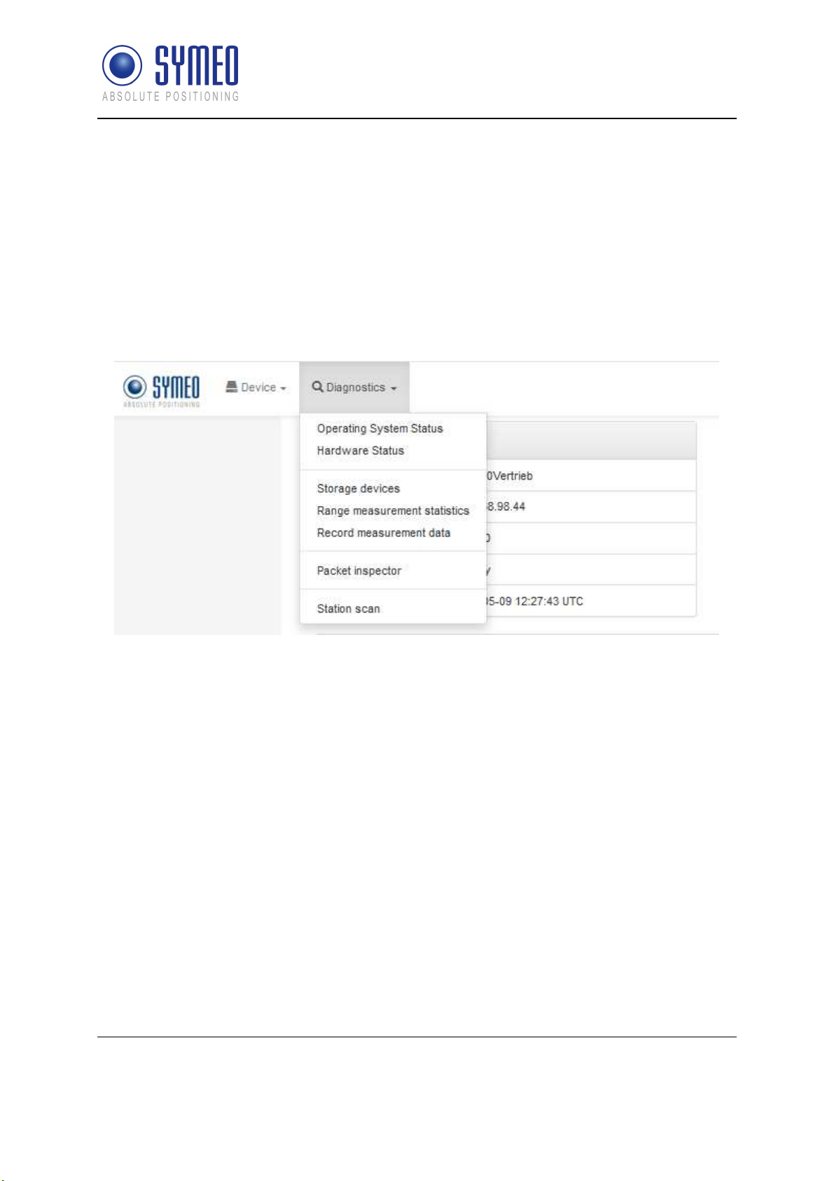
8.2 Diagnostics
SYMEO Local Positioning Radar System
Product Family LPR®-1DHP-200 – Product Documentation
In this menu (see
Figure 8.22
), the following subpages are available:
Operating System Status
Hardware Status
Storage device
Range measurement statistics
Record measurement data
Packet inspector
Station scan
Figure 8.22: Diagnostics Menu
8.2.1 Diagnostics – Operating System Status
Under this menu (see Figure 8.23), following information is available:
Device information
Uptime, Memory
Networking information
Filesystem
Software version
In case of problems, this information may be requested by Symeo support.
Device Setup via the Web User Interface
Copyright © Symeo GmbH 2018
DOC.EDO.000341.WORK.EN_LPR-1DHP-200_Product-Documentation.docx
Page 52 of 71

SYMEO Local Positioning Radar System
Product Family LPR®-1DHP-200 – Product Documentation
Figure 8.23: Diagnostics - Operating System Status
Device Setup via the Web User Interface
Copyright © Symeo GmbH 2018
DOC.EDO.000341.WORK.EN_LPR-1DHP-200_Product-Documentation.docx
Page 53 of 71

SYMEO Local Positioning Radar System
Product Family LPR®-1DHP-200 – Product Documentation
8.2.2 Diagnostics – Hardware Status
In this menu (see Figure 8.24), system values and system voltages are displayed.
In case of problems, this information may be requested by Symeo support.
Figure 8.24: Diagnostics - Hardware Status
This display is automatically refreshed every 5 seconds.
Device Setup via the Web User Interface
Copyright © Symeo GmbH 2018
DOC.EDO.000341.WORK.EN_LPR-1DHP-200_Product-Documentation.docx
Page 54 of 71

SYMEO Local Positioning Radar System
Product Family LPR®-1DHP-200 – Product Documentation
8.2.3 Diagnostics – Storage Devices
Here (see Figure 8.25) you can see available storage devices and format them if necessary.
Figure 8.25: Diagnostics - Storage Devices
8.2.4 Diagnostics – Range Measurement Statistics
This section (see Figure 8.26) allows you to view raw measurements and range statistics.
Please select a topic from the menu on the left (see Figure 8.26) to view the
corresponding information:
Live range measurement
Signal strength statistics
Measurement rate statistics
Figure 8.26: Diagnostics - Range Measurement Statistics
Device Setup via the Web User Interface
Copyright © Symeo GmbH 2018
DOC.EDO.000341.WORK.EN_LPR-1DHP-200_Product-Documentation.docx
Page 55 of 71

SYMEO Local Positioning Radar System
Product Family LPR®-1DHP-200 – Product Documentation
Live Range Measurement
In this menu (see Figure 8.27), the current distance and the current RSSI value (Signal
strength) will be displayed, furthermore, the distance over time graph.
Figure 8.27: Diagnostics - Distance over time graph
By pointing the mouse in the graph and using the scroll wheel, you can downsize or enlarge
the timeline.
Device Setup via the Web User Interface
Copyright © Symeo GmbH 2018
DOC.EDO.000341.WORK.EN_LPR-1DHP-200_Product-Documentation.docx
Page 56 of 71

Signal Strength Statistics
SYMEO Local Positioning Radar System
Product Family LPR®-1DHP-200 – Product Documentation
Figure 8.28: Diagnostics - RSSI over distance diagram
This diagram shows the recorded distance-signal strength pairs since the last power-on. You
can use it to detect abnormal signal propagation routes at certain constellations of the two
LPR® stations, as the signal strength should decrease with increasing distance.
The diagram is automatically refreshed every 10 seconds.
The distance axis displays the distance between the two LPR® stations, and the RSSI axis
the received signal strength in dB. As the signal strength at specific distances may vary, the
statistical distribution of the signal strength is also recorded. Displayed are the mean
received signal strength, the 10 % quantile and the 90 % quantile. The quantiles give you
information about how many recorded signal strength values were lower than the
corresponding line. 10 % of the recorded signal strengths were lower than the 10 % quantile
line and 90 % were lower than the 90 % quantile line, leaving 80 % in between those two
lines. This way you get an idea of the signal strength distribution per distance without
including extreme outliers. This helps identifying distances with increased signal distortions
(e.g. due to multipath signal propagation), as the variance of the signal strength there usually
increases.
Device Setup via the Web User Interface
Copyright © Symeo GmbH 2018
DOC.EDO.000341.WORK.EN_LPR-1DHP-200_Product-Documentation.docx
Page 57 of 71

Measurement Rate Statistics
SYMEO Local Positioning Radar System
Product Family LPR®-1DHP-200 – Product Documentation
Figure 8.29: Diagnostics - Measurement rate over distance diagram
This diagram shows the recorded distance-measurement rate pairs since the last power-on.
You can use it to detect systematical measurement errors at certain constellations of the two
LPR® stations, as the measurement rate decreases in this case.
The diagram is automatically refreshed every 10 seconds.
The distance axis displays the distance between the two LPR® stations, and the
measurement rate axis the current rate of range measurements in Hertz. As the
measurement rate at specific distances may vary, the statistical distribution of the
measurement rate is also recorded. Displayed are the mean measurement rate, the 10 %
quantile and the 90 % quantile. The quantiles give you information about how many recorded
measurement rate values were lower than the corresponding line. 10 % of the recorded
measurement rates were lower than the 10 % quantile line and 90 % were lower than the 90
% quantile line, leaving 80 % in between those two lines. This way you get an idea of the
measurement rate distribution per distance without including extreme outliers. This helps
identifying distances with increased errors in range measurement (e.g. due to multipath
signal propagation), as the measurement rate decreases as errors are encountered.
Device Setup via the Web User Interface
Copyright © Symeo GmbH 2018
DOC.EDO.000341.WORK.EN_LPR-1DHP-200_Product-Documentation.docx
Page 58 of 71

SYMEO Local Positioning Radar System
Product Family LPR®-1DHP-200 – Product Documentation
8.2.5 Diagnostics – Record Measurement Data
In this menu, you can
Change logging mode
View recorded measurements
Click the drop-down menu window “Change logging mode” to choose the logging mode.
The following options are available:
Disabled
Log to SD card if available
Log to USB stick if available, use SD card as fallback
Log to USB stick if available (recommended
Choose one of the settings (recommended log to USB stick if available) and refresh the
page using the F5 key.
8.2.6 Diagnostics – Packet Inspector
In this menu (see Figure 8.30), you can see the output of the binary port.
For it, you must press the "Get new data" button to get at first the last 10 records. Then you
must select one record by driving over with the mouse and pressing the left mouse button.
By expanding of “Hexadecimal view” and/or “Detailed view”, you can view this data in the
appropriate format.
Device Setup via the Web User Interface
Copyright © Symeo GmbH 2018
DOC.EDO.000341.WORK.EN_LPR-1DHP-200_Product-Documentation.docx
Page 59 of 71

SYMEO Local Positioning Radar System
Product Family LPR®-1DHP-200 – Product Documentation
.
Figure 8.30: Diagnostics - Packet inspector
8.2.7 Diagnostics – Station Scan
In this menu (see Figure 8.31), all Symeo units found in your current local area network
(LAN) will be displayed.
Device Setup via the Web User Interface
Copyright © Symeo GmbH 2018
DOC.EDO.000341.WORK.EN_LPR-1DHP-200_Product-Documentation.docx
Page 60 of 71

SYMEO Local Positioning Radar System
Product Family LPR®-1DHP-200 – Product Documentation
Figure 8.31: Diagnostics - Station scan
Device Setup via the Web User Interface
Copyright © Symeo GmbH 2018
DOC.EDO.000341.WORK.EN_LPR-1DHP-200_Product-Documentation.docx
Page 61 of 71

SYMEO Local Positioning Radar System
Product Family LPR®-1DHP-200 – Product Documentation
9 The Customer Protocol
The customer protocol (Binary Protocol XP) is the standard data protocol between LPR®1DHP-200 units and users for exchanging measurement and relay data with the help of
different data types in binary data format. The transfer of a data packet of a certain data type
is done in single data frames. The data can be transferred either via TCP/IP or UDP protocol.
All settings related to the customer protocol can be found in the WebUI
under Device -> Settings -> Customer protocol
The default TCP/IP and UDP port of the customer protocol interface is
3046.
The customer protocol is not output on slave units.
9.1 General Description
9.1.1 Structure of a Data Type
Each data type has a fixed structure and length.
data type.
Each data packet begins with the START symbol (0x7e). TYPE indicates the type of the data
packet. The DATA field contains the relevant data. The CRC-field contains the check sum.
The data type ends with the END symbol (0x7f).
All multi byte integers (e.g. CRC field) are encoded in Network-Byte-Order (Big-Endian). All
signed integers are represented in two's complement.
A custom protocol length which is bigger than the standard protocol
length can be set. The data packet is then zero-padded (after the END
symbol) to the selected protocol frame length before the data packet is
sent.
Figure 9.1: Structure of a data type
Figure 9.1
shows the general structure of a
9.1.2 CRC
The CRC-16-IBM with polynomial x16+x15+x2+1 is used for the CRC. The CRC is calculated
over the TYPE and DATA field.
The Customer Protocol
Copyright © Symeo GmbH 2018
DOC.EDO.000341.WORK.EN_LPR-1DHP-200_Product-Documentation.docx
Page 62 of 71

SYMEO Local Positioning Radar System
Content
Length
Value
Data type
Product Family LPR®-1DHP-200 – Product Documentation
9.2 Data Types
9.2.1 Type 0x16 – Distance Data
Direction: LPR®-1DHP-200 Unit → User
The data type 0x16 is the standard output data type. It contains measurement data, system
status information and settings. The default protocol frame length is 47 bytes.
Table 9.1 shows the structure of a 0x16 data packet.
The standard customer protocol length of the LPR®-1DHP(-R) sensor
(predecessor) was 50 bytes which has to be taken into account if a
LPR®-1DHP-200 is used to replace it.
The data packets are output with the internal update rate or the chosen update rate.
The internal measurement rate depends on the used radar mode, FFT
size and averaging setting. The output rate of the interface equals the
internal measurement rate if no custom output interval is set.
(byte)
START 1 0x7E unsigned integer
TYPE 1 0x16 unsigned integer
Sync Channel 2 0x#### unsigned integer
Distance [mm] 4 0x#### #### signed integer
Velocity [mm/s] 4 0x#### #### signed integer
Signal Level [dB/10] 2 0x#### signed integer
Temperature [°C/100] 2 0x#### signed integer
Counter 4 0x#### #### unsigned integer
Age 2 0x#### unsigned integer
Error 2 0x#### unsigned integer
System Mode 2 0x#### unsigned integer (Bit mask)
Diversity Status 2 0x#### unsigned integer
Internal service information 16
CRC 2 0x#### unsigned integer
END 1 0x7F unsigned integer
Table 9.1: Data Type 0x16 - Distance Data Output for Group Master (47 bytes)
The Customer Protocol
Copyright © Symeo GmbH 2018
DOC.EDO.000341.WORK.EN_LPR-1DHP-200_Product-Documentation.docx
Page 63 of 71

SYMEO Local Positioning Radar System
Product Family LPR®-1DHP-200 – Product Documentation
Example of Distance Data (hex):
7E 16 10 24 00 00 0B 11 FF FF FF 35 FC C6 11 C6 00 02 54 AE 00 00 00 00 FF FF 00 00 00 00 00
00 00 00 00 00 00 00 00 00 00 0C 7D 48 C6 74 7F
7E
START byte
hex
16
TYPE (0x16: Distance Data)
hex
10 24
00 00 0B 11
FF FF FF 35
FC C6
11 C6
00 02 54 AE
00 00
00 00
Sync channel
hex
= 2833
hex
= -203
hex
= 64710
hex
= 4550
hex
Age
hex
Error status: 0 means no error; unequal 0 means error
hex
dec
= 152750
hex
Distance: 2833 mm
dec
Velocity: -203 mm/s
dec
Level: 64710 – 65536 = -826 -> -82.6 dB
dec
Temperature: 45.5 C
Counter
dec
(error description see section “Distance Error Codes"
below)
FF FF
00 00
System mode
hex
Diversity status
hex
00 00 00 00 00 00 00 00 00 00 00 00 00 0C 7D 48
C6 74
Cyclic redundancy check
hex
7F
END byte
hex
internal service information
hex
The Customer Protocol
Copyright © Symeo GmbH 2018
DOC.EDO.000341.WORK.EN_LPR-1DHP-200_Product-Documentation.docx
Page 64 of 71

SYMEO Local Positioning Radar System
Value
Content
Description
Product Family LPR®-1DHP-200 – Product Documentation
Distance Error Codes
The following errors are indicated in the error field in the distance data type:
(hex)
0x00 No error Measurement valid
0x01 No peak detected No measurement signal
0x02 Peak too low Measurement signal is imprecise
0x03 Currently not used
0x04 Implausible speed Velocity is outside the defined velocity limits
0x05 Measurement botched Measurement is not feasible
0x06 Currently not used
0x07 Currently not used
0x08 Currently not used
0x09 Settling VCXO has just been tuned, needs time to settle
0x0a PT2 filter reset Filter reset after inconclusive distance measurements
0x0b Planned reset System is going to reboot
0x0c Currently not used
0x0d Currently not used
0x0e Distance out of Range
Peak is close to the edge of the spectrum. Value is
unreliable.
0x0f Currently not used
0x10 Currently not used
0x11 ARM sync failed
The ARM9 boards of the Group Master have not been
synchronized.
Error 18 (0x12) will be reported if no valid target is
0x12 Target out of range
detected within system range and an internal system
check will confirm error-free system operation.
Table 9.2: Distance error codes
Only measurements with error code 0 are valid.
9.2.2 Type 0x03 – Relays Switching Commands
Direction: LPR®-1DHP-200 Unit → User / LPR®-1D24
The Customer Protocol
Copyright © Symeo GmbH 2018
DOC.EDO.000341.WORK.EN_LPR-1DHP-200_Product-Documentation.docx
Page 65 of 71

SYMEO Local Positioning Radar System
Content
Length (byte)
Value
Data Type
Product Family LPR®-1DHP-200 – Product Documentation
The data type 0x03 is typically used for sending relay switching commands to a LPR®-1D24
radar unit (with installed relays) or to a PLC. The default protocol frame length is 9 bytes.
Table 9.3 shows the structure of a 0x03 data packet.
START 1 0x7E unsigned integer
TYPE 1 0x03 unsigned integer
Destination (LPR®-1D24 address)
Relay Selection (Bitmask) (Bit
2 0x####
See chapter 9.2.3
1 0x## unsigned integer
1..4 Relay 1..4)
Bit significance 0-7 starting with 0
as the lowest (set) Bit value.
Relay Switch (Bitmask) 1 0x## unsigned integer
CRC 2 0x#### unsigned integer
END 1 0x7F unsigned integer
Table 9.3: Data Type 0x03 - Relays Switching Command (9 bytes)
With the relay selection (bitmask) the relays which shall be controlled are selected. The
relays that are chosen within the relay selection bitmask will be switched according to the
relay switch bitmask.
Example: A relay selection value = 0x14
11111111
bin
will switch relays 2 and 4 ON - the state of the other relays remains unchanged.
hex
= 00010100
bin
and a relay switch value = 0xFF
hex
=
The Customer Protocol
Copyright © Symeo GmbH 2018
DOC.EDO.000341.WORK.EN_LPR-1DHP-200_Product-Documentation.docx
Page 66 of 71

SYMEO Local Positioning Radar System
Product Family LPR®-1DHP-200 – Product Documentation
9.2.3 LPR®-1D24 Address
LPR® unit addresses are completely defined by a 16 bit value:
0 Reserved
Group-ID: The Group-ID of the unit (1..1022)
Station-ID:
for Distance Data:
for Relays Switching Command:
The Station-ID of the unit (SID)
Master and Slave SID is always 2 (SID = 2)
SID = 1 for Master und SID = 2 for Slave
Table 9.4: LPR®-1D24 address
The Customer Protocol
Copyright © Symeo GmbH 2018
DOC.EDO.000341.WORK.EN_LPR-1DHP-200_Product-Documentation.docx
Page 67 of 71

Product Family LPR®-1DHP-200 – Product Documentation
10 Technical Data
10.1 General Technical Data
SYMEO Local Positioning Radar System
LPR®-1DHP-220-R
LPR®-1DHP-260
LPR®-1DHP-281
LPR®-1DHP-290
Frequency range
Supply voltage
Power consumption
Ambient
Temperature
Protection class
housing
Housing dimensions
(LxWxH); weight
Interfaces
External connector
57,0 – 64,0 GHz 57,0 – 64,0 GHz
11 - 36 V 11 - 36 V
7 W 2 x 7 W
-40 °C to +70°C -40 °C to +70°C
IP65 IP65
95 x 95 x 155 mm; 800g 160 x 230 x 220 mm; 4kg
Ethernet (TCP/IP, Profinet) Ethernet (TCP/IP, Profinet)
Ethernet (M12), supply voltage
(M12)
LPR®-1DHP-280
(2x LPR®-1DHP-281 + MTM102512)
2 x Ethernet (M12), 2 x supply
voltage (M12)
Antenna
Compliance
Integrated, beam width = +-2,5° Integrated, beam width = +-2,5°
CE, FCC, IC (others on request) CE, FCC, IC (others on request)
Technical Data
Copyright © Symeo GmbH 2018
DOC.EDO.000341.WORK.EN_LPR-1DHP-200_Product-Documentation.docx
Page 68 of 71

SYMEO Local Positioning Radar System
Product Family LPR®-1DHP-200 – Product Documentation
10.2 Mode Dependent Technical Data
The following tables depict the technical data, which are dependent on the used Radar
Mode, the used Bandwidth Mode and your regional settings.
10.2.1 Primary Radar Mode
General Technical Data
Bandwidth Mode 0,5 GHz 2 GHz
Measurement
accuracy
Repeatability
Measurement
rate
up to +- 10 mm up to +- 5 mm
up to +- 6 mm up to +- 3 mm
up to 350 Hz up to 350 Hz
ETSI Specific Technical Data
Bandwidth Mode 0,5 GHz 2 GHz
Measuring range
2 m to 50 m 1 m to 50 m
FCC Specific Technical Data
Bandwidth Mode 0,5 GHz 2 GHz
Measuring range
2 m to 50 m 1 m to 20 m
10.2.2 Secondary Radar Mode
General Technical Data
Bandwidth Mode 0,5 GHz 2 GHz
Measurement
accuracy
Repeatability
Copyright © Symeo GmbH 2018
DOC.EDO.000341.WORK.EN_LPR-1DHP-200_Product-Documentation.docx
Page 69 of 71
up to +- 10 mm up to +- 5 mm
up to +- 6 mm up to +- 3 mm
Technical Data

SYMEO Local Positioning Radar System
Product Family LPR®-1DHP-200 – Product Documentation
Measurement
rate
up to 110 Hz up to 110 Hz
ETSI Specific Technical Data
Bandwidth Mode 0,5 GHz 2 GHz
Measuring range
2 m to 300 m 0,5 m to 300 m
FCC Specific Technical Data
Bandwidth Mode 0,5 GHz 2 GHz
Measuring range
2 m to 300 m 0,5 m to 225 m
10.2.3 Diversity Radar Mode
General Technical Data
Bandwidth Mode 0,5 GHz 2 GHz
Measurement
accuracy
Repeatability
Measurement
rate
up to +- 10 mm up to +- 5 mm
up to +- 6 mm up to +- 3 mm
up to 110 Hz up to 110 Hz
ETSI Specific Technical Data
Bandwidth Mode 0,5 GHz 2 GHz
Measuring range
2 m to 500 m 0,5 m to 500 m
FCC Specific Technical Data
Technical Data
Copyright © Symeo GmbH 2018
DOC.EDO.000341.WORK.EN_LPR-1DHP-200_Product-Documentation.docx
Page 70 of 71

SYMEO Local Positioning Radar System
Product Family LPR®-1DHP-200 – Product Documentation
Bandwidth Mode 0,5 GHz 2 GHz
Measuring range
2 m to 500 m 0,5 m to 225 m
10.3 Product Name vs. Model Number
Each device is labeled with a model / product name which corresponds to a unique model
number.
Model / Product name Model Number
LPR®-1DHP-220-R BSW200220
LPR®-1DHP-260 BSW200260
LPR®-1DHP-281 BSW200281
LPR®-1DHP-290 BSW200290
Copyright © Symeo GmbH 2018
DOC.EDO.000341.WORK.EN_LPR-1DHP-200_Product-Documentation.docx
Page 71 of 71
 Loading...