

Symeo BSV101757 Users Manual

SYMEO LOCAL POSITIONING RADAR
Product: LPR®-1D24 (Symeo BSV101757)
Product Documentation
Table of Content
Copyright © SYMEO GmbH 2009
Date: August 2009
LPR-1D24_Users_Manual_FCC-IC-Edition_EN.docx Page 1 of 34

SYMEO Local Positioning Radar System
LPR®-1D24
LPR®-1D24 Station – Overview and Mounting
Content
1 GENERAL INFORMATION ........................................................................................ 6
1.1 Safety Instructions .................................................................................................... 6
1.2 Mounting .................................................................................................................... 6
1.3 Repairs....................................................................................................................... 6
1.4 Transport and Storage .............................................................................................. 6
1.5 Power Supply ............................................................................................................ 6
1.6 Setup and Operation ................................................................................................. 7
1.7 System Extensions and Accessories ...................................................................... 7
1.8 Additional Instructions ............................................................................................. 7
1.9 General Requirements for Compliance of Radio Apparatus .................................. 7
2 OVERVIEW OF LPR®-1D24 UNIT .............................................................................. 8
2.1 Technical Data LPR®-1D24 Unit ............................................................................... 9
3 MOUNTING AND ALIGNMENT OF LPR®-1D24 UNITS ........................................... 10
3.1 Mounting of the Fall Protection .............................................................................. 11
4 REQUIREMENTS FOR POWER SUPPLY ............................................................... 12
5 SPECIFICATION OF THE CONNECTORS .............................................................. 13
5.1 Overview of Connections ....................................................................................... 13
5.2 Power Supply .......................................................................................................... 14
5.2.1 Plugs ......................................................................................................................... 14
5.2.2 Pin Assignment ......................................................................................................... 14
5.3 Ethernet M12 ........................................................................................................... 14
5.3.1 Plugs ......................................................................................................................... 15
5.3.2 Pin Assignment ......................................................................................................... 15
5.3.3 Connector Cable M12 – RJ45 ................................................................................... 15
5.4 USB – mini ............................................................................................................... 15
5.4.1 Plugs ......................................................................................................................... 16
5.5 USB – A Devices ..................................................................................................... 16
General Information
Copyright © SYMEO GmbH 2015
LPR-1D24_Users_Manual_FCC-IC-Edition_EN.docx Page 2 of 34

SYMEO Local Positioning Radar System
LPR®-1D24
LPR®-1D24 Station – Overview and Mounting
6 LPR®-1D24 HOUSING DIMENSIONS ...................................................................... 17
7 WEB USER INTERFACE FOR LPR®-1D24 .............................................................. 18
7.1 Requirements .......................................................................................................... 18
7.1.1 Connection to LPR®-1D24 Unit ................................................................................. 18
7.2 Open User Interface ................................................................................................ 20
7.3 Device ...................................................................................................................... 22
7.4 Device - Device Configuration ............................................................................... 23
7.4.1 Device - Device Configuration – LAN ........................................................................ 24
7.4.2 Device - Device Configuration – System Time .......................................................... 26
7.5 Device - Application Settings ................................................................................. 26
7.5.1 Device - Application Settings – Customer Protocol ................................................... 27
7.5.2 Device - Application Settings – General ................................ .................................... 27
7.6 Diagnostics ............................................................................................................. 30
7.6.1 Diagnostics - Operating System Status ..................................................................... 31
7.6.2 Diagnostics - Hardware Status .................................................................................. 32
7.6.3 Diagnostics - Distance over Time .............................................................................. 33
7.6.4 Diagnostics - Signal Strength over Distance Diagram ............................................... 34
General Information
Copyright © SYMEO GmbH 2015
LPR-1D24_Users_Manual_FCC-IC-Edition_EN.docx Page 3 of 34

SYMEO Local Positioning Radar System
LPR®-1D24
LPR®-1D24 Station – Overview and Mounting
Table of Figures
Figure 1: LPR®-1D24 measurement path .............................................................................. 8
Figure 2: LPR®-1D24 unit inclusive mounting bracket ...........................................................10
Figure 3: Mounting of the fall protection ................................................................................11
Figure 4: LPR®-1D24 Connectors .........................................................................................13
Figure 5: M12 Connector for the power requirement ............................................................14
Figure 6: M12 Ethernet M12 .................................................................................................15
Figure 7: LPR®-1D24 Housing Dimensions ..........................................................................17
Figure 8: Network Settings ...................................................................................................19
Figure 9: Ping LPR®-1D24 unit .............................................................................................19
Figure 10: Homepage of the LPR®-1D24 unit .......................................................................20
Figure 11: Sign in on the home page of the LPR®-1D24 unit ................................................ 21
Figure 12: Device Menu .......................................................................................................22
Figure 13: Information overview and device status ...............................................................22
Figure 14 – Device: Device Configuration Menu ...................................................................23
Figure 15 – Device: Device Configuration - LAN Settings .....................................................24
Figure 16 – Device: Device Configuration LAN Settings - Commit the change .....................25
Figure 17 – Device: Device Configuration LAN Settings - Changes have been applied ........25
Figure 18 – Device: Device Configuration - SystemTime Settings ........................................26
Figure 19 – Device: Application Settings ..............................................................................27
Figure 20 – Device: Application Settings - Costumer Protocol Settings ................................27
Figure 21 – Device: Application Settings – General Settings ................................................28
Figure 22: Example configuration of one measurement pair Master and Slave Unit .............29
Figure 23 – Diagnostics Menu ..............................................................................................30
Figure 24 – Diagnostics: Operating System Status ...............................................................31
Figure 25 – Diagnostics: Hardware Status............................................................................32
Figure 26 – Diagnostics: Distance over time .........................................................................33
Figure 27 – Diagnostics: Signal strength over distance diagram ...........................................34
General Information
Copyright © SYMEO GmbH 2015
LPR-1D24_Users_Manual_FCC-IC-Edition_EN.docx Page 4 of 34
SYMEO Local Positioning Radar System
Version
Date
Description
1.00
29.01.2016
Initial Release
This symbol appears before instructions that must be followed at all times.
Failure to comply with these instructions will result in personal injury.
This symbol appears before instructions that must be followed at all times.
Failure to comply with these instructions will result in damage to
equipment.
This symbol appears before information of particular importance.
LPR®-1D24
LPR®-1D24 Station – Overview and Mounting
The documentation for the LPR®-1D24 Local Positioning Radar System is published by:
SYMEO GmbH
Prof.-Messerschmitt-Str. 3
D-85579 Neubiberg
www.symeo.de
If you have any questions or suggestions, please contact:
Email: info@symeo.com
phone: +49 89 660 7796 0
Copyright Symeo GmbH 2010
All rights reserved
HISTORY
SYMBOLS USED
The following symbols are used throughout the documentation:
All rights reserved, particularly those relating to the translation, reprinting, and reproduction
by photocopying or similar processes of all or part of the documentation.
All rights reserved, particularly for purposes of the award of patents or submission of utility
models.
Delivery options and technical changes reserved.
Published by SYMEO GmbH
General Information
Copyright © SYMEO GmbH 2015
LPR-1D24_Users_Manual_FCC-IC-Edition_EN.docx Page 5 of 34
1 General Information
1.1 Safety Instructions
LPR®-1D24 Systems are purely tracking and assistance systems. They
therefore do not satisfy special requirements for personal safety.
Follow the safety instructions in this documentation!
1.2 Mounting
All mounting, installation and maintenance work must be carried out by
an electrically qualified or trained person!
1.3 Repairs
SYMEO Local Positioning Radar System
LPR®-1D24
LPR®-1D24 Station – Overview and Mounting
Repairs on the devices should only be performed by Symeo GmbH.
1.4 Transport and Storage
Use the original packaging or other suitable packaging for returns and
whenever the system is to be transported. This ensures protection from
crushing, impact, moisture and electrostatic discharge.
During setup and before operation, refer to the instructions for
environmental conditions in this document and in the data sheet.
Place the cables in such a way so that they do not build the possible
cause of risk and are not damaged.
1.5 Power Supply
While installing or using it in open-air, the transient overvoltage cannot
be excluded. Here, overvoltage protection is to be used for low voltage
in accordance to DIN EN 61643-21 and IEC 61643-21.
While connecting the plug and sockets, please observe the
correspondent chapter in this document "Specification of Connectors".
Do not use damaged cables (damaged insulation, bare wires). A
defective cable may cause a fire hazard.
Be careful that the device can be damaged with reverse polarity despite
of strict implementation of polarity reversal protection. In that case the
unit must be sent to the SYMEO service for further testing.
General Information
Copyright © SYMEO GmbH 2015
LPR-1D24_Users_Manual_FCC-IC-Edition_EN.docx Page 6 of 34
SYMEO Local Positioning Radar System
LPR®-1D24
LPR®-1D24 Station – Overview and Mounting
1.6 Setup and Operation
During mounting, make sure that no objects or liquids reach inside the
device (risk of short-circuit).
In case of emergency (e.g. damaged housing, control elements or power
cables, penetration of liquids or foreign bodies) switch off the device
immediately, disconnect from the power line the device and inform your
SYMEO service.
Protect the contacts of all sockets and plugs of the device from static
electricity. Avoid touching the contacts. If touching the contacts is
unavoidable, then one should take the following precautions: Touch a
grounded object or wear a ground strap before touching the contacts.
This will dissipate static charges.
The device must be secured against falling.
The LPR®-1D24 unit must not be opened.
1.7 System Extensions and Accessories
Data cables to peripheral devices must be shielded properly.
For LAN cabling, the requirements apply in accordance with EN 50173
and EN 50174-1/2. Use of either a Category 5 shielded cable for 10/100
Ethernet or Category 5e shielded cable for Gigabit Ethernet is a
minimum requirement. The specifications of standard ISO/IEC 11801
must be complied with.
The warranty becomes void in case of any damages caused by
replacement of components on the device during installation.
1.8 Additional Instructions
Changes or modifications not expressly approved by the party
responsible for compliance could void the user’s authority to operate the
equipment.
1.9 General Requirements for Compliance of Radio Apparatus
This device complies with Part 15 of the FCC Rules and with Industry
Canada license-exempt RSS standard(s). Operation is subject to the
following two conditions: (1) this device may not cause harmful
interference, and (2) this device must accept any interference received,
including interference that may cause undesired operation.
General Information
Copyright © SYMEO GmbH 2015
LPR-1D24_Users_Manual_FCC-IC-Edition_EN.docx Page 7 of 34
SYMEO Local Positioning Radar System
Distance measurement and user data
transmission
LPR®-1D24
LPR®-1D24
LPR®-1D24 Station – Overview and Mounting
2 Overview of LPR®-1D24 Unit
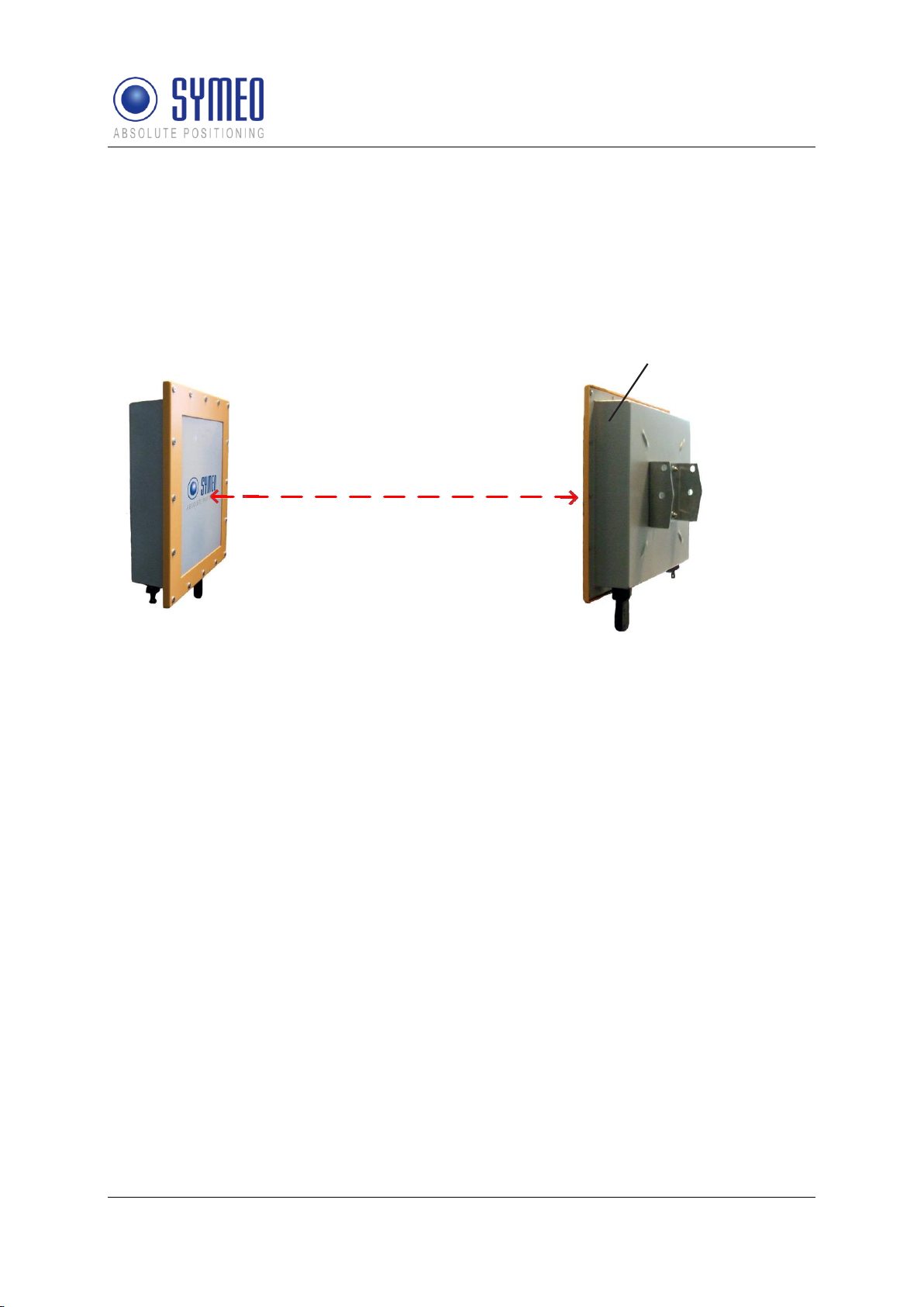
LPR®-1D24 is a highly precise radio sensor for distance measurement. Two paired units
allow for long range applications and enable additional data transfer at the same time. The
exact position of a moving machine component, e.g. a crane or crane trolley, can thus be
dynamically determined in real-time, while data collected at one end (e.g. a load cell input) is
available at the paired unit simultaneously.
Figure 1: LPR®-1D24 measurement path
In addition to the distance reading, the relative approach speed of the LPR® sensors is
available. Distance and speed can be used for internal collision avoidance decisions at
predetermined distance thresholds. Optional on-board relays will be activated. All data is
made available at standard interfaces.
The devices are easy to install and operate. Rough alignment between the facing units is
sufficient, even for very long distances. The multi-channel radio antenna is integrated into the
robust housing. A built-in terminal server allows straightforward configuration of the unit ID,
the paired unit ID and other parameters in any browser.
Symeo LPR® radio works highly reliable under adverse conditions. Interference with any WiFi
equipment operating in parallel can be excluded at all times. A unique ID per each unit allows
operating multiple pairs in immediate vicinity.
LPR®-1D24 sensors are maintenance-free and paired sensors can be interconnected with
other pairs, providing several distances at a single interface, e.g. for crane xy position
acquired by two sensor pairs.
Overview of LPR®-1D24 Unit
Copyright © SYMEO GmbH 2015
LPR-1D24_Users_Manual_FCC-IC-Edition_EN.docx Page 8 of 34

SYMEO Local Positioning Radar System
LPR®-1D24
LPR®-1D24 Station – Overview and Mounting
2.1 Technical Data LPR®-1D24 Unit
The technical specifications for LPR®-1D24 can be found in our data-sheet under the
following link:
http://www.symeo.com/cms/upload/pdf/en/DataSheets/Symeo_Datasheet_LPR-1D24.pdf
Overview of LPR®-1D24 Unit
Copyright © SYMEO GmbH 2015
LPR-1D24_Users_Manual_FCC-IC-Edition_EN.docx Page 9 of 34
SYMEO Local Positioning Radar System
The device must be secured against falling.
All mounting, installation and maintenance work must be carried out by
electrician or a person with similar training and skills!
LPR®-1D24
LPR®-1D24 Station – Overview and Mounting
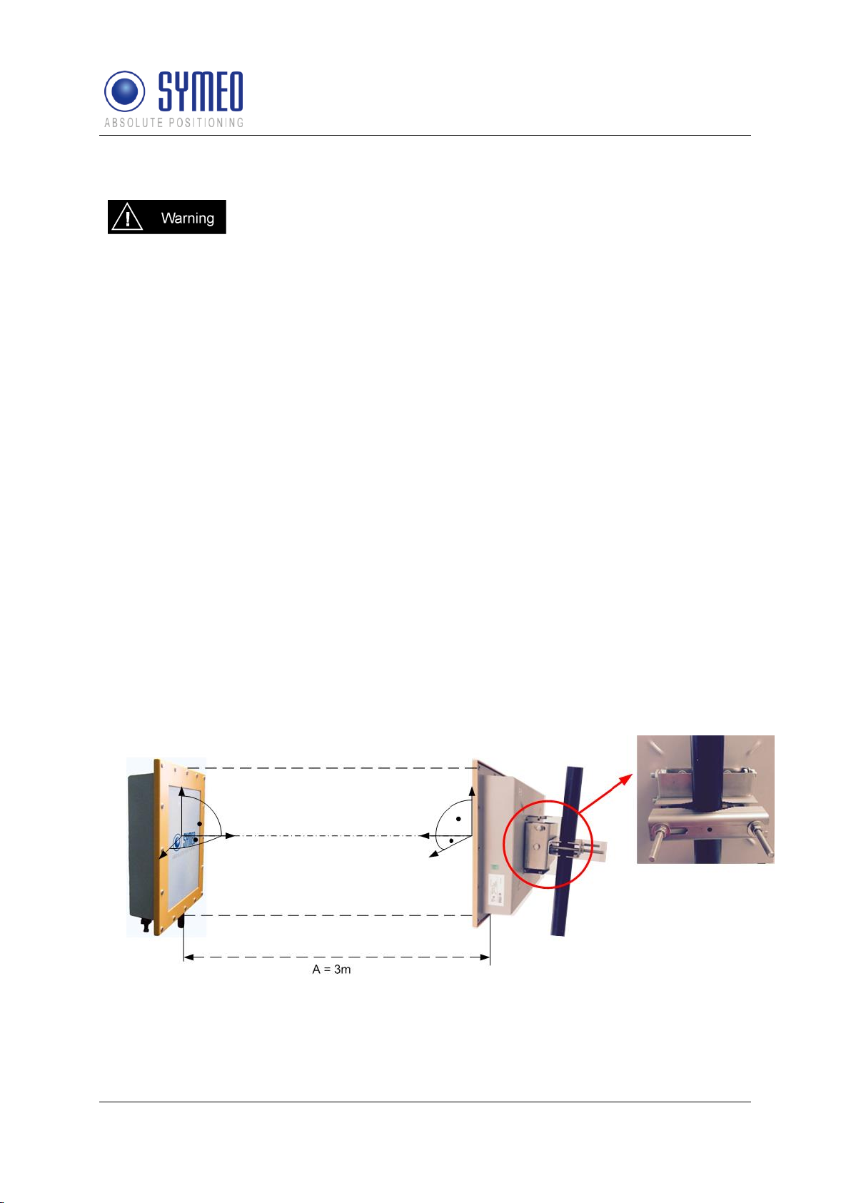
3 Mounting and Alignment of LPR®-1D24 Units
The LPR®-1D24 units are delivered with a separate mounting bracket (see Figure 2).
Figure 2 shows a complete system including the mounting bracket. The bracket must be
mounted with a pipe clamp on a pipe. The pipe diameter is best chosen between 40 mm and
75 mm. For mounting, a flat wrench of SW 13 is required.
For mounting the system, please proceed as follows:
At a suitable place, mount the LPR®-1D24 unit to a suitable pipe with the bracket. To
adjust the system, do not tighten the mounting bracket finally. Specified alignments have
to be adhered to if indicated by Symeo.
A minimum distance of 3 meters between the measuring system units must be
maintained to guarantee the specified accuracy. Mounting closer than the minimum
distance decreases the accuracy at close proximity.
The units must have the same orientation for mounting, for example both units with
connectors downwards. For outdoor use the units have to be mounted with the
connectors downwards.
Now adjust the system on the opposite side.
The two system units should be mounted opposite to each other and possibly should not
be an offset horizontal and vertical from each other or twisted.
Now fix the system by tightening the screws in the mounting bracket and the mounting
bracket on pipe in such a way that no modification is possible anymore. Flat wrench SW
13 is required.
Figure 2: LPR®-1D24 unit inclusive mounting bracket
Mounting and Alignment of LPR®-1D24 Units
Copyright © SYMEO GmbH 2015
LPR-1D24_Users_Manual_FCC-IC-Edition_EN.docx Page 10 of 34
SYMEO Local Positioning Radar System
C
A
B
LPR®-1D24
LPR®-1D24 Station – Overview and Mounting
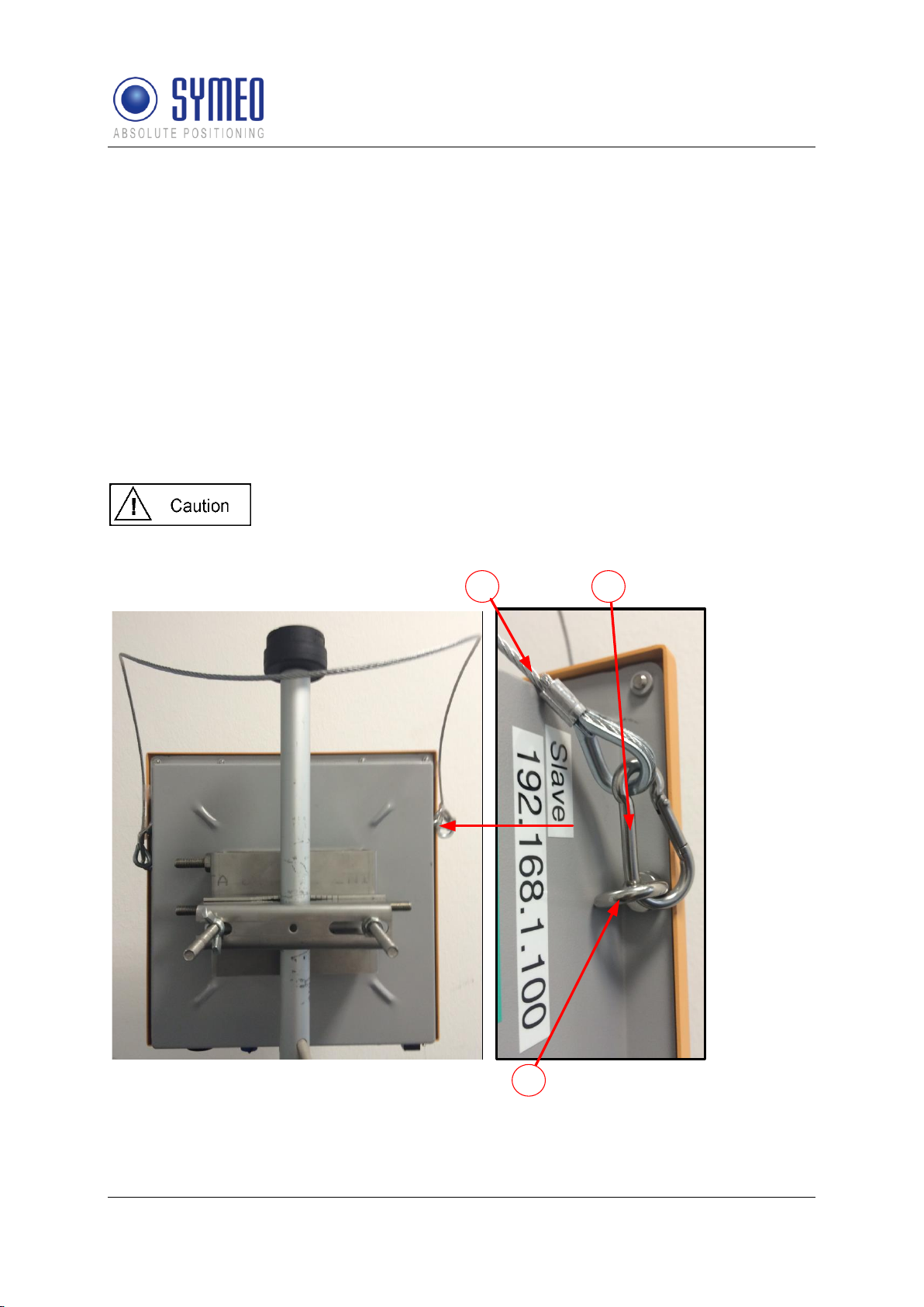
3.1 Mounting of the Fall Protection
The LPR®-1D24 units must be protected against fall. For every unit Symeo provides a
protection set consisting of the following components:
A: 2 x ring nuts M5,
B: 2 x snap hooks 5 x 50 mm
C: 1 x steel cable 3 mm x 1 m
The two ring nuts must be mounted on the back of the LPR®-1D24 unit laterally on the
respective second screw from above, which are 4 mm longer than the other screws. Then
the snap hook must be attached to the ring nuts. Please put the steel cable around a pipe or
a bracket and hang it also in the snap hook (see picture below).
The backup set should be installed before the assembly of the unit to
secure it against falling.
Figure 3: Mounting of the fall protection
Mounting and Alignment of LPR®-1D24 Units
Copyright © SYMEO GmbH 2015
LPR-1D24_Users_Manual_FCC-IC-Edition_EN.docx Page 11 of 34
 Loading...