

Symeo BSB000900 User Manual

SYMEO LOCAL POSITIONING RADAR
Product: LPR®-1DXi
Product Documentation

SYMEO Local Positioning Radar System
LPR®-1DXi
Product Documentation
Content
1 OVERVIEW ................................................................................................................ 5
1.1 Safety Instructions .................................................................................................... 5
1.2 Installation ................................................................................................................. 6
1.3 Repairs....................................................................................................................... 6
1.4 Transport and Storage .............................................................................................. 6
1.5 Power Supply ............................................................................................................ 6
1.6 Setup and Operation ................................................................................................. 6
1.7 System Extensions and Accessories ...................................................................... 7
1.8 Additional Instructions ............................................................................................. 7
2 SYSTEM DESCRIPTION ............................................................................................ 8
2.1 Mode of Operation .................................................................................................... 8
2.2 Technical Data ........................................................................................................... 8
2.3 System Configuration ............................................................................................... 9
2.4 System Design ................................ ................................................................ .......... 9
2.4.1 Station-ID (SID) ........................................................................................................... 9
2.4.2 Group-ID (GID) ........................................................................................................... 9
2.4.3 Frequency Channel ................................................................................................... 10
2.5 Versions of LPR®-1DXi Units .................................................................................. 10
3 HARDWARE ............................................................................................................ 11
3.1 Component Setup of the LPR®-1DXi Unit .............................................................. 11
3.2 Cable Glands, Interfaces and LED Display of the LPR®-1DXi Unit ...................... 12
3.3 Opening Angle of the integrated Antenna ............................................................. 13
4 INSTALLATION ........................................................................................................ 14
4.1 Important Instructions for Installation ................................................................... 14
4.2 Power Connection .................................................................................................. 14
4.3 RS 232 Connection ................................................................................................. 15
Overview
Copyright © Symeo GmbH 2014
Page 2 of 38

SYMEO Local Positioning Radar System
LPR®-1DXi
Product Documentation
4.4 Relay Connection .................................................................................................... 15
4.5 Mounting .................................................................................................................. 16
4.6 Installation Notes for Antennas ............................................................................. 17
4.6.1 Fresnel Zone ............................................................................................................. 17
4.6.2 Alignment of LPR®-1DXi Units................................................................................... 18
5 COMMISSIONING .................................................................................................... 18
5.1 Requirements .......................................................................................................... 18
5.2 Commissioning Tool – LPR®-1DXi Wizard ............................................................ 19
5.2.1 Installation of USB driver ........................................................................................... 19
5.2.2 Installation of the Symeo Wizard ............................................................................... 19
5.2.3 Utilization of LPR® 1DXi Wizard ................................................................................ 20
6 PROTOCOL DESCRIPTION .................................................................................... 32
6.1 General Description ................................................................................................ 32
6.1.1 Structure of Data Packet ........................................................................................... 32
6.1.2 Byte Stuffing ............................................................................................................. 32
6.1.3 CRC .......................................................................................................................... 33
6.2 Data Types ............................................................................................................... 33
6.2.1 Type 0x00 – Distance Data ....................................................................................... 33
6.2.2 Example of Distance Data ......................................................................................... 33
6.3 Remarks ................................................................................................................... 34
6.3.1 LPR®-1DXi Address .................................................................................................. 34
6.3.2 Status Field ............................................................................................................... 34
6.3.3 Error Messages ......................................................................................................... 35
7 APPENDIX A: AGENCY CERTIFICATIONS ............................................................ 36
United States (FCC) and Canada (Industry Canada) ........................................................ 36
United States (FCC) ............................................................................................................ 37
Canada (Industry Canada) ................................................................................................. 37
8 APPENDIX B: TABLE OF COUNTRIES AND REGULATIONSFEHLER! TEXTMARKE NICHT DEFINIERT.
Overview
Copyright © Symeo GmbH 2014
Page 3 of 38
SYMEO Local Positioning Radar System
Version
Date
Description
1.02
17.06.2010
USB driver installation changed
1.03
06.08.2010
Added notes for FCC/IC
1.04
18.05.2011
New Product ID with Production Codes
1.05
15.03.2012
New Wizard v4.x
1.06
29.07.2014
Updated FCC/IC notes
This symbol appears before instructions that must be followed at all times.
Failure to comply with these instructions will result in personal injury.
This symbol appears before instructions that must be followed at all times.
Failure to comply with these instructions will result in damage to
equipment.
This symbol appears before information of particular importance.
LPR®-1DXi
Product Documentation
The documentation for the LPR®-1DXi Local Positioning Radar System is published by:
SYMEO GmbH
Prof.-Messerschmitt-Str. 3
D-85579 Neubiberg
www.symeo.de
If you have any questions or suggestions, please contact:
Email: info@symeo.com
Phone: +49 89 660 7796 0
Copyright Symeo GmbH 2014
All Rights Reserved
HISTORY
SYMBOLS USED
The following symbols are used throughout the documentation:
All rights reserved, particularly those relating to the translation, reprinting, and reproduction
by photocopying or similar processes of all or part of the documentation.
All rights reserved, particularly for purposes of the award of patents or submission of utility
models.
Delivery options and technical changes reserved.
Published by SYMEO GmbH
Overview
Copyright © Symeo GmbH 2014
Page 4 of 38
SYMEO Local Positioning Radar System
Overview of Interfaces
Power Supply
10-36 Volt via terminal block inside casing
USB
Parameter setting with Symeo Wizard (for Windows PC)
Relays
7 dry contact relays via terminal block inside casing
RS232
Distance reading via terminal block inside casing
LPR®-1DXi
Product Documentation
1 Overview
SYMEO Industrial Local Positioning Radar (LPR®) is a system for contactless, real-time
determination of distances between two devices by means of radio signals.
All components are integrated in one casing. The compact unit can therefore be mounted
very easily and operate maintenance-free, even under harsh conditions. Dust, fog, or similar
impacts do not influence the system.
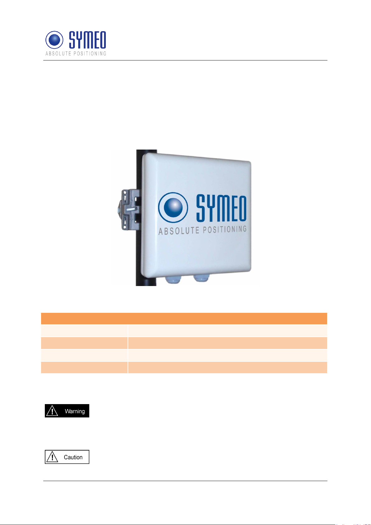
The Local Positioning Radar System LPR®-1DXi consists of equal units, which are
configured with the software Symeo-Wizard (via Windows PC with USB connection):
Figure 1 – LPR®-1DXi unit
The LPR®-1DXi unit has different interfaces. The unit has IP65 protection class.
1.1 Safety Instructions
LPR® systems are purely tracking and assistance systems. They therefore
do not satisfy special requirements for personal safety, e.g. performance
level c.
Follow the safety instructions in this documentation!
Keep these safety instructions and other documents together with the device.
Copyright © Symeo GmbH 2014
Page 5 of 38
Overview

1.2 Installation
All installation, repair and servicing work must be carried out by qualified
and trained technicians!
1.3 Repairs
Repairs to the device must be carried out by authorized technicians.
Unauthorized opening and incorrect repairs could result in severe danger to
the user (danger of electric shock, radiated energy, fire hazard).
1.4 Transport and Storage
Use the original packaging or other suitable packaging for returns and
whenever the system is to be transported. This ensures protection from
crushing, impacts, moisture and electrostatic discharge.
During setup and before operation, refer to the instructions for
environmental conditions included in the operating instructions for the
device.
Route the wires in such a way that they do not cause a hazard and are not
damaged. When connecting the wires, refer to the corresponding
instructions in the operating instructions for the device. Do not drop the
device.
SYMEO Local Positioning Radar System
LPR®-1DXi
Product Documentation
1.5 Power Supply
A safety-inspected power cable that satisfies the regulations of the country
of use is required for the device.
The device must not be operated unless the nominal voltage of the device
matches the values in the data sheet, described below. Check the supply
voltage of the device in stationary devices.
When connecting and disconnecting wires, refer to the instructions in the
operating instructions for the device.
Do not use any damaged wires (damaged insulation, exposed wires). A
faulty wire poses a risk of electric shock or fire hazard.
1.6 Setup and Operation
During installation, make sure that no objects or fluids get inside the device
In emergencies (e. g. if there is damage to the housing, control elements or
the mains cable, if fluids or foreign bodies have infiltrated the equipment),
switch off the power supply to the device immediately and notify your
SYMEO Service.
Overview
Copyright © Symeo GmbH 2014
Page 6 of 38
SYMEO Local Positioning Radar System
LPR®-1DXi
Product Documentation
Protect the contacts of all of the device's sockets and plugs from static
electricity. Do not touch the contacts. If it is ever necessary to touch the
contacts, take the following precautionary measures: Touch a grounded
object or carry a ground strap before touching the contacts. This will divert
static charges.
Proper operation (in accordance with IEC60950/EN60950) of the device is
only assured if the housing is fully installed (electric shock, cooling, fire
protection). If necessary, refer to the corresponding instructions in the
operating instructions for the device.
In the case of high outside temperatures and intense, direct solar radiation
or other radiant heat, it may be necessary to provide a sun or heat shield.
1.7 System Extensions and Accessories
Data links to peripheral devices must be provided with adequate shielding.
The warranty shall be voided if you cause defects to the device by installing
or exchanging system extensions.
1.8 Additional Instructions
The LPR®-1DXi unit must not be opened except for installation. The LPR®-
1DXi unit contains no serviceable components.
When opening, ensure that no fluid gets into the housing. When sealing the
unit, ensure that the seal is included in the cover and that the LPR®-1DXi
unit is completely closed. Otherwise, moisture can penetrate the unit and
damage it.
Please take note of the safety and operating instructions in the operating
instructions for the system in which you want to install the component.
Overview
Copyright © Symeo GmbH 2014
Page 7 of 38

SYMEO Local Positioning Radar System
Overview: Technical Data
Frequency range
5.725-5.875 GHz, ISM band
Transmitting power
Max. 0.025 W / 14 dBm
Positive signal control to
opposite unit
up to 1800 m
Switch thresholds
/distance reading
0 to 120 m (option – extended distance reading 0 to 500 m)
Distance output
0,5 m increments (option – higher resolution: up to ± 5 cm *1)
Repeat rate
Up to 30 Hz
Power supply
10-36 V DC
Power consumption
6 W
Ambient temperature
-40°C to +75°C
Protection class
IP 65
Casing dimensions
190 x 190 x 80 mm (without supplied mounting bracket)
Weight LPR 1DXi
1,5 kg
Weight mounting bracket
1 kg
Interfaces
USB for parameter setting with Symeo Wizard (for Win PC);
Serial RS 232 with binary protocol (terminal block inside
casing);
7x dry contact relays (terminal block inside casing), each
max. 60 VDC, max. 2 A
Compliance
CE mark, part 15 FCC*2, RSS-210*2
LPR®-1DXi
Product Documentation
2 System Description
2.1 Mode of Operation
The distance is determined by measuring the transit time of radio signals. One unit initiates
the measurement and the second unit replies.
With the software Symeo-Wizard (via Windows PC) the distances for adjustable switching
points are determined and transferred to the LPR®-1DXi device. Upon reaching a switching
threshold, on-board relays open dry contacts. Relays are available on both units. Remote
units can be configured via the built-in radio interface. Optional the distance reading is also
available on both of the units.
LPR®-1DXi units use the same frequency band and the same hardware for communicating
as for measuring distance. This means that no external WLAN or cable networks are needed
for transmitting measurement values and setting switching relays.
2.2 Technical Data
*1 Depending on distance and application parameters
*2 Only valid for FCC labeled units
Copyright © Symeo GmbH 2014
Page 8 of 38
System Description
SYMEO Local Positioning Radar System
LPR®-1DXi
Product Documentation
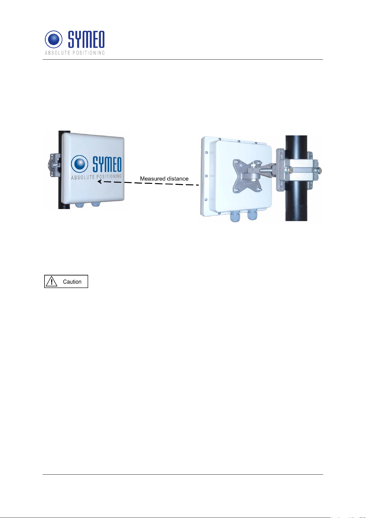
2.3 System Configuration
The LPR®-1DXi system consists of two LPR®-1DXi units. For distance measurement and
collision-avoidance, the two units are arranged as shown in Figure 2. The distance readings
and relays are available at both of the paired units.
Figure 2: LPR®-1DXi system
2.4 System Design
Each LPR® 1DXi unit has parameters to provide an explicit allocation to a system and also to
ensure the functionality of a system. These parameters are explained in the following:
Parameters may only be set with the commissioning tool Symeo Wizard as
described in chapter 5.4. Do not change parameters manually in the
configuration files.
2.4.1 Station-ID (SID)
Each unit has an explicit identification Number in one system. A system consists of 2 units.
The first unit has the station number 1 (SID 1), the second unit has the station number 2 (SID
2).
2.4.2 Group-ID (GID)
A pair of LPR®-1DXi units is identified clearly by its group number. The two units in one
system have the same group number. If there is used a second, a third or more system in
your environment, all additional systems must have a different group number.
System Description
Copyright © Symeo GmbH 2014
Page 9 of 38

SYMEO Local Positioning Radar System
Overview: Options
ID
Production
Code
Measurement
distance
Distance output
resolution
Basic device
BSB000900
src
0 to 120 m
0,5m increments
Option 1
BSB000900
srl
0 to 500 m
0,5m increments
Option 2
BSB000900
scp
0 to 120 m
Resolution up to ±5 cm
Option 3
BSB000900
slp
0 to 500 m
Resolution up to ±5 cm
Basic device *1
BSB000900
srcf
0 to 120 m
0,5m increments
Option 1 *1
BSB000900
srlf
0 to 500 m
0,5m increments
Option 2 *1
BSB000900
scpf
0 to 120 m
Resolution up to ±5 cm
Option 3 *1
BSB000900
slpf
0 to 500 m
Resolution up to ±5 cm
LPR®-1DXi
Product Documentation
2.4.3 Frequency Channel
The measurement takes place in a frequency band width of 5,725 to 5,875 GHz. In this band
width a frequency channel is assigned to the LPR®-1DXi system. 30 different frequency
channels are available. Two units in one LPR®-1DXi system need the same frequency
channel.
If there are more LPR®-1DXi systems in your environment each further
LPR®-1DXi system needs different frequency channels. The frequency
channel is linked to the group ID. Therefore it is required to use different
group IDs for different LPR®-1DXi systems in the same environment. You
can set the group IDs with the commissioning tool LPR®-1DXi Symeo
Wizard (see chapter 5).
2.5 Versions of LPR®-1DXi Units
For the LPR®-1DXi units several different versions are available:
*1
in compliance with part 15 off FCC rules and with RSS-210 of Industry Canada
Copyright © Symeo GmbH 2014
Page 10 of 38
Please take care that the distances for the switching points in your
application are within the maximum possible distance range of your version
of LPR®-1DXi.
The distance for positive signal control, monitoring the functionality of two
units, is possible up to 1800m.
System Description
SYMEO Local Positioning Radar System
LPR®-1DXi
Product Documentation
3 Hardware
All corresponding installation, repair and servicing work must be carried out
by qualified and trained technicians.
3.1 Component Setup of the LPR®-1DXi Unit
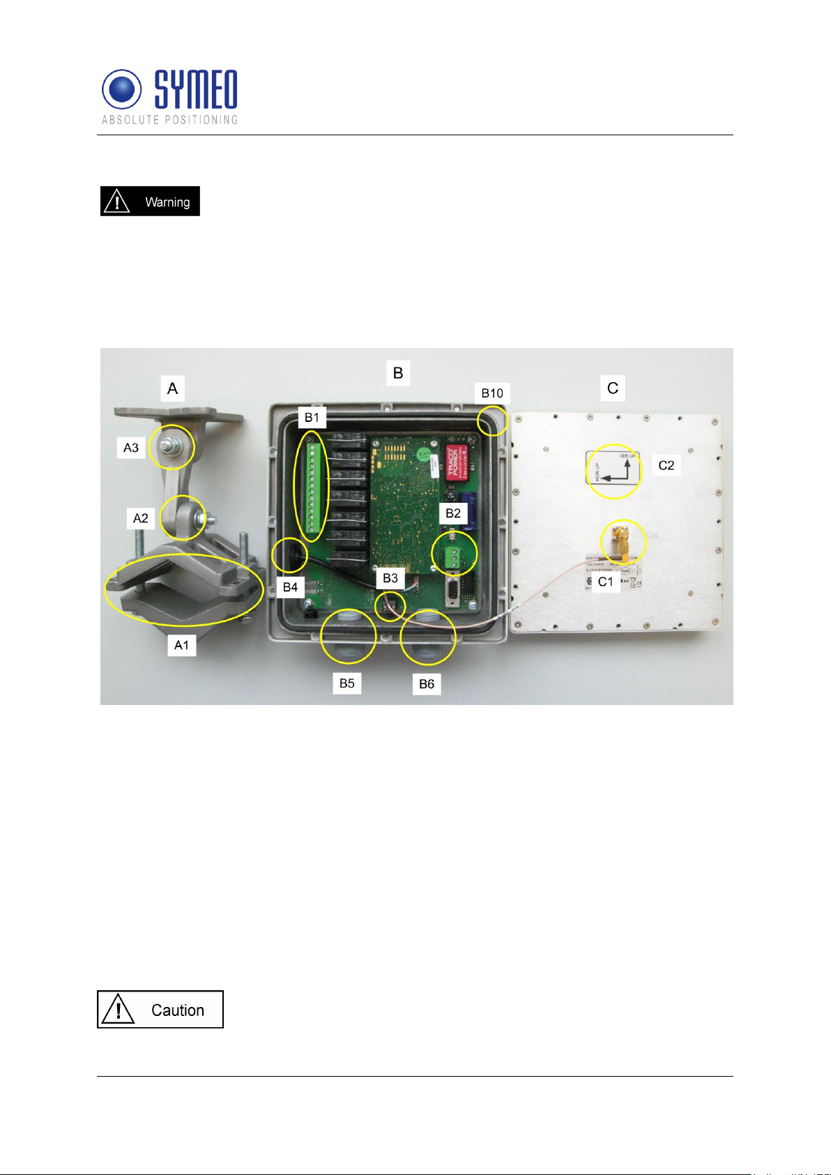
The LPR®-1DXi unit consists of mounting bracket A, casing with electronic devices B and
antenna C as shown in Figure 3.
Figure 3 Components of the LPR®-1DXi: mounting bracket A, casing with electronic devices B
and antenna C
A: mounting bracket
A1 mounting kit for pole and wall mounting
A2 adjustment of elevation angle
A3 adjustment of azimuth angle
B: casing with electronic device
B1 terminal block for relays
B2 terminal block for power connection
B3 terminal block for serial RS232 (distance output, binary protocol)
B4 USB port for parameter setting
B5 cable gland for relay cable to relay connector
B6 cable gland for power supply cable and optional serial RS232 cable
B10 seal
C: Antenna
C1 connector for antenna cable
C2 orientation of antenna polarization
The seal (B10) seals front and rear element when it is mounted
correctly. Otherwise the housing will not be sealed in a water-proof
manner.
Hardware
Copyright © Symeo GmbH 2014
Page 11 of 38

SYMEO Local Positioning Radar System
LPR®-1DXi
Product Documentation
The antenna C has to be mounted in correct polarization (C2) as
shown in Figure 3
3.2 Cable Glands, Interfaces and LED Display of the LPR®-1DXi
Unit
The casing B has two cable glands for power cable (B6) and cable for the connection to the
on-board relays (B5). Additionally the pressure equalization membrane (B7) is shown.
Figure 4: Casing B side view with cable glands and mounting bracket A
B5 Cable gland for cable to relays
B6 Cable gland for power cable with optional wires for serial RS232
B7 pressure equalization membrane
Pressure equalization membrane (B7) must not be removed or
loosened. Otherwise the housing will not be sealed in a water-proof
manner.
Power supply cable must be within 5 to 9 mm diameter, and relay
cable must be within 7 to 13 mm diameter, both with a round crosssection.
Hardware
Copyright © Symeo GmbH 2014
Page 12 of 38
 Loading...