

Page 1

PTC-860IM
User's Guide
Page 2

On December 1, 2000 Symbol T echnologies, Inc. completed the purchase
of Telxon Corporation. References made throughout this document to
"Telxon" or "Telxon Corporation" are be replaced with "Symbol" or
"Symbol Technologies, Inc.", respectively. Any questions, contact your
Symbol representative.
© 2000 by Symbol Technologies, Inc. All rights reserved.
No part of this publication may be reproduced or used in any form, or by any electrical or
mechanical means, without permission in writing from Symbol. This includes electronic or
mechanical means, such as photocopying, recording, or information storage and retrieval
systems. The material in this manual is subject to change without notice.
Symbol reserves the right to make changes to any software or product to improve reliability ,
function, or design.
Symbol does not assume any product liability arising out of, or in connection with, the
application or use of any product, circuit, or application described herein.
No license is granted, either expressly or by implication, estoppel, or otherwise under any
Symbol Technologies, Inc., intellectual property rights. An implied license only exists for
equipment, circuits, and subsystems contained in Symbol products.
Symbol is a registered trade mar k of Symbo l Technologies, Inc. Other product names
mentioned in this manual may be trademarks or registered trademarks of their respective
companies and are hereby ack nowl edg ed.
Symbol Technologies, Inc.
One Symbol Pl aza
Holtsville, New York 11742-1300
http://www.symbol.com
Symbol Support Center: 1- 800 -653- 53 50
2
Page 3
GUIDE TO THE
PTC-860
Optical Models
Page 4

G
uide to the PTC-860
Optical Models
Part Number: 14767-701-03
Release Date: 10/20/94
Page 5

Telxon and TCAL (Telxon Common Applica tion Language ) are
registered tradem arks of Telxon Corporation.
MS-DOS is a re gis tered trademark of M icrosoft Corporation.
IBM is a registered trademark of International Business
Machines, Inc .
The information contained in t his m anual is subject to change
without notice.
Telxon Corporation shall not be liable for technical or editorial
omissions or mistakes in this manual nor shal l i t be l ia bl e for
incidental or consequential damages resulting from your use of
the information contained in this manual.
This manual is copyrighted. All rights ar e reser ved. No part of
this manual may be photocopied or reproduced in any form
without the prior w r itten consent of Telxon.
© Copyright 1993 T elxon Corporation
All Rights Reserved.
Page 6

ÄÄ
ontents
C
FCC statement
Safety information
PTC-860NI . . . . . . . . . . . . . . . . . . . . . . . . . . . . 9
Responsibility for use . . . . . . . . . . . . . . . . . . . . 9
Use in hazardous locations . . . . . . . . . . . . . . . . . 9
Disposing of nickel-cadmium batteries . . . . . . . . . . . . 12
Overview of the PTC-8 6 0
Entering data . . . . . . . . . . . . . . . . . . . . . . . . . . 13
Through the keyboard . . . . . . . . . . . . . . . . . . . 14
With a bar-code reader . . . . . . . . . . . . . . . . . . . 14
Via cloning or downloading . . . . . . . . . . . . . . . . 14
Communicating data . . . . . . . . . . . . . . . . . . . . . . 14
Models . . . . . . . . . . . . . . . . . . . . . . . . . . . . . 15
Getting started
PTC-860 optical models (PTC-860, PTC-860ES, and
PTC-860NI) . . . . . . . . . . . . . . . . . . . . . . . . . 16
Unpacking the PTC-860 . . . . . . . . . . . . . . . . . . . . 16
Turning on the backup battery . . . . . . . . . . . . . . . . 17
Charging the battery pack . . . . . . . . . . . . . . . . . . . 19
Checking the PTC-860 . . . . . . . . . . . . . . . . . . . . . 21
. . . . . . . . . . . . . . . . . . . . . . . . . . . . . . . . . 22
Parts
25-pin connector . . . . . . . . . . . . . . . . . . . . . . . . 22
Application flash EPROM . . . . . . . . . . . . . . . . . . . 22
Backup battery . . . . . . . . . . . . . . . . . . . . . . . . . 23
Bar-code reader (optional) . . . . . . . . . . . . . . . . . . . 23
Battery charger . . . . . . . . . . . . . . . . . . . . . . . . . 25
Battery compartment . . . . . . . . . . . . . . . . . . . . . 25
Battery recharge posts . . . . . . . . . . . . . . . . . . . . . 26
Display . . . . . . . . . . . . . . . . . . . . . . . . . . . . . 26
Elastic strap . . . . . . . . . . . . . . . . . . . . . . . . . . 26
Keyboard . . . . . . . . . . . . . . . . . . . . . . . . . . . . 26
. . . . . . . . . . . . . . . . . . . . . . . . . . . . . 8
. . . . . . . . . . . . . . . . . . . . . . . . . . . 9
. . . . . . . . . . . . . . . . . . . . . . 13
. . . . . . . . . . . . . . . . . . . . . . . . . . . . 16
4
Page 7

ENTER/YES key . . . . . . . . . . . . . . . . . . . . . . 27
ON/OFF key . . . . . . . . . . . . . . . . . . . . . . . . 27
SHIFT key . . . . . . . . . . . . . . . . . . . . . . . . . 27
Keyboard overlay . . . . . . . . . . . . . . . . . . . . . . . . 28
Optical coupler . . . . . . . . . . . . . . . . . . . . . . . . . 28
Screwdriver . . . . . . . . . . . . . . . . . . . . . . . . . . . 28
Wand port (PTC-860 only) . . . . . . . . . . . . . . . . . . . 28
Features
Connecting accessories
Scanning bar-code labels
Communicating data
. . . . . . . . . . . . . . . . . . . . . . . . . . . . . . . 29
Automatic off . . . . . . . . . . . . . . . . . . . . . . . . . . 29
Automatic return at on . . . . . . . . . . . . . . . . . . . . 29
Backlight . . . . . . . . . . . . . . . . . . . . . . . . . . . . 29
Beeper . . . . . . . . . . . . . . . . . . . . . . . . . . . . . . 30
Clock . . . . . . . . . . . . . . . . . . . . . . . . . . . . . . 30
Memory . . . . . . . . . . . . . . . . . . . . . . . . . . . . . 30
Power backup system . . . . . . . . . . . . . . . . . . . . . 30
. . . . . . . . . . . . . . . . . . . . . . . . 31
Connecting an accessory . . . . . . . . . . . . . . . . . . . . 31
Through the 25-pin connector . . . . . . . . . . . . . . . 31
Through the wand port (PTC-860 only) . . . . . . . . . . 33
Removing an accessory . . . . . . . . . . . . . . . . . . . . . 34
From the 25-pin connector . . . . . . . . . . . . . . . . . 34
From the wand port (PTC-860 only) . . . . . . . . . . . 34
. . . . . . . . . . . . . . . . . . . . . . . 35
. . . . . . . . . . . . . . . . . . . . . . . . . 36
Using the optical coupler . . . . . . . . . . . . . . . . . . . 36
Using the 25-pin connector . . . . . . . . . . . . . . . . . . 37
Connecting a cable . . . . . . . . . . . . . . . . . . . . . 37
Disconnecting a cable . . . . . . . . . . . . . . . . . . . 38
Cloning . . . . . . . . . . . . . . . . . . . . . . . . . . . . . 38
Maintaining the PTC-860
Operating conditions . . . . . . . . . . . . . . . . . . . . . . 40
PTC-860 . . . . . . . . . . . . . . . . . . . . . . . . . . . 40
PTC-860ES . . . . . . . . . . . . . . . . . . . . . . . . . 40
PTC-860NI . . . . . . . . . . . . . . . . . . . . . . . . . 40
. . . . . . . . . . . . . . . . . . . . . . . 40
5
Page 8

Handling the PTC-860 . . . . . . . . . . . . . . . . . . . . . 41
Storing the PTC-860 . . . . . . . . . . . . . . . . . . . . . . 42
Cleaning the PTC-860 . . . . . . . . . . . . . . . . . . . . . 42
Servicing the PTC-860 . . . . . . . . . . . . . . . . . . . . . 43
Replacing the batteries
Removing the batteries . . . . . . . . . . . . . . . . . . . . 44
Installing new batteries . . . . . . . . . . . . . . . . . . . . 45
AFAT nickel-cadmium battery pack . . . . . . . . . . . 45
AA alkaline batteries . . . . . . . . . . . . . . . . . . . . 46
Backup battery . . . . . . . . . . . . . . . . . . . . . . . 48
Troubleshooting
The PTC does not turn on . . . . . . . . . . . . . . . . . . . 49
The bar-code reader fails to read a label . . . . . . . . . . . 49
The PTC shows a “Backup Battery Fault” message when
you turn it on . . . . . . . . . . . . . . . . . . . . . . . . 49
Other problems or difficulties with your PTC-860 . . . . . . 49
Appendix A
Specifications . . . . . . . . . . . . . . . . . . . . . . . . . . 50
Appendix B
Hardware part numbers . . . . . . . . . . . . . . . . . . . . 52
Appendix C
Communication connections . . . . . . . . . . . . . . . . . . 55
. . . . . . . . . . . . . . . . . . . . . . . . . . . . . . 50
Electrical . . . . . . . . . . . . . . . . . . . . . . . . . . 50
Environmental . . . . . . . . . . . . . . . . . . . . . . . 50
Physical . . . . . . . . . . . . . . . . . . . . . . . . . . . 50
. . . . . . . . . . . . . . . . . . . . . . . . . . . . . . 52
. . . . . . . . . . . . . . . . . . . . . . . . . . . . . . 55
. . . . . . . . . . . . . . . . . . . . . . . . 44
. . . . . . . . . . . . . . . . . . . . . . . . . . . 49
Glossary
Index
. . . . . . . . . . . . . . . . . . . . . . . . . . . . . . . 61
. . . . . . . . . . . . . . . . . . . . . . . . . . . . . . . . . 64
6
Page 9

Figures
1.Backup battery switch . . . . . . . . . . . . . . . . . . . 18
2.Parts of the PTC-860 . . . . . . . . . . . . . . . . . . . . 24
3.Accessory fasteners . . . . . . . . . . . . . . . . . . . . . 32
4.Using the accessory locking latch . . . . . . . . . . . . . 33
5.Inserting a battery pack . . . . . . . . . . . . . . . . . . 45
6.Inserting AA alkaline batteries into the plastic
battery case . . . . . . . . . . . . . . . . . . . . . . . 47
7.PTC-to-IBM PC/AT cable . . . . . . . . . . . . . . . . . 55
8.PTC-to-IBM PC/XT cable . . . . . . . . . . . . . . . . . 56
9.Clone cable . . . . . . . . . . . . . . . . . . . . . . . . . 57
10.PTC-to-1/2 duplex modem cable . . . . . . . . . . . . . . 58
11.PTC-to-full duplex modem cable . . . . . . . . . . . . . 59
12.PTC-to-host (DTE) cable . . . . . . . . . . . . . . . . . . 60
Tables
1.Hazardous (classified) locations in accordance with
Article 500, National Electrical Code - 1990 . . . . . . 10
2.Hardware part numbers . . . . . . . . . . . . . . . . . . 52
7
Page 10

ÄÄ
CC
F
statement
This equipment has been tested and found t o com p ly wi th t he
limits for a Class A digital d ev ice pursuant to Part 15 of
Federal Communications Commission (FCC) rules. These
limits are des i gned to provide reasonable protection agains t
harmful interferen ce w h en t h e e quipment is operated in a
commercial environment. This equipment generates, uses , and
can radiate radio frequency energy and, if not insta lled and
used in accordance w it h this operator’s guide, may cause
harmful interferen ce to radio communications. Operation of
this equipment in a residential area is likely to cause harmful
interference, in which case users will be required to correct the
interference at their own expense.
8
Page 11

y
y
ÄÄ
afety
S
information
©
PTC-860NI
Responsibility for use
The standards used b y Telxon for evaluation of the PTC-860NI
(Non-Incendive) equipment’s suitability for use in the
Hazardous Loca tions specified herein are applicable in the
United States and may not be applicable outside of the United
States. It is the cus to mer’s respons i bility to determine whether
the NI unit will meet the regulatory/safety requirements for its
operation and in the cus tomer’s jurisdiction.
The customer also assumes full responsibility for the
determinatio n of the proper class of ele ct rical equipment for
use in the Hazardous Locations of its operations in compliance
with applicable laws, regulations , and safety standards . Telxon
expressly disclaims any responsibility for such determination.
The PTC-860NI uses a Telxon AFAT nickel-cadmium battery
pack (Telxon part number 14861-000). This battery pack is the
only pack app ro v ed for use with the PTC -860NI.
The PTC-860NI is not us er- or field-service ab le be
batter
Use in hazardous locations
The PTC-860NI is appro v ed for use in Class I, Division 2,
Groups A, B, C, and D; Class II, Division 2, Groups E, F, and G;
and Class III Hazardous Locations.
replacement.
ond
9
Page 12

In hazardous locations, the PTC-86 0NI’s on ly user
interface is its keyboard; the access ory ports ar e n ot
suitable for use in hazardou s locations.
WARNING! Remove the PTC-860NI from the potentially
hazardous area if the unit is damaged or suspected of being
damaged.
WARNING! Remove the PTC-860NI from the potentially
hazardous location should the location become hazardous
due to failure of containment systems, equipment, or other
causes that would expose the unit t o volatile substances.
TABLE 1
Hazardous (classified) locations in accordance with Article 500,
National Electrical Code - 1990
Class I
Flammable gases or vapors
Division 2
•
Liquids and gases are in closed co ntainers, or t he
systems are handled, processed, or used
•
Concentrations are normally prevented by positive
mechanical ventilation
•
Adjacent to a Class I, Division 1 location
Group A:
Group B:
Group C:
Group D:
Atmospheres containing acetylene
Atmospheres such as acrolein, butadiene, ethylene oxide,
hydrogen, propylene oxide, or gases or vapors equivalent in
hazard to hydrogen, such as manufactured gas
Atmospheres such as cyclopropane, ethylene, ethyl ether, or
gases or vapors equivalent in hazard
Atmospheres such as acetone, alcohol, ammonia, benzine,
benzol, butane, gasoline, hexane, lacquer solvent vapors,
naphtha, natural gas, propane, or gases or vapors equivalent
in hazard
10
Page 13

Class II
Combustible dusts
Division 2
•
Not normally in the air
•
Accumulations normally sufficient to interfere with normal
operation of ele c tr ic a l eq uipment or other appa r atus
•
In the air as a result of infrequent malfunctioning of
- handling equipment
- process equipment
•
Accumulations are sufficient to interfere with the safe
dissipation of heat from electrical equipment
•
Accumulation s may be ignitible by abnor ma l or fa il ur e of
electrical equipment
Group E:
Group F:
Group G:
Atmospheres contai ni ng com bu st i bl e me tal dusts
(regardless of resistivity), dusts of similarly
hazardous charac t eri sti c s (< 10 0 kΩ/cm), or
electrically c on d uc ti v e d us t s
Atmospheres containing combustible carbon black,
charcoal, or coke dusts that have > 8% total volatile
material or if these dusts are sensitized so that
they present an explosio n hazard and have a
resistivity > 100 kΩ/cm but ≤ 100 MΩ/cm
Atmospheres containing combustible dusts
having a resistivity > 100 kΩ/cm or electrically
nonconductive dusts
11
Page 14

y
y
Class III
Ignitible fibers or flyings
Division 1
•
Fibers or materials
producing
combustible flyings
are manufactur e d,
stored, or handl ed
Not grouped
•
Manufacturers
such as textile
mills, cottonrelated mills, or
clothing plants
•
Fibers and flyings
including cotton,
hemp, jute, rayon,
sisal, and spanish
moss
Division 2
•
Fibers are handled
or stored exce p t
during the process
of manufact ure
Note: The previous information provides only general
guidelines on the envir onm ents in which a PTC-860NI is
approved for use. Each hazardous location i n wh ic h a
PTC-860NI will be used must be inspected and approved
the Occupational Safety and Health Administration
b
(OSHA), the local fire marshall, and the c ustomer’s
insurance compan
©
Disposing of nickel-cadmium batteries
.
Nickel-cadmi um batteries contain c h em ically active materials
that are hazardous to t he environment; therefore, t hey s ho uld
be disposed of properly. Never attempt to incinerate a
nickel-cadmium battery; doing so could cause it to explode.
Telxon urges you to contact the Environmental Protection
Agency, the Department of Natural Resources, a local
hazardous waste disposal agency, or the Telxon Customer
Support Center for assistance prior to disposing of your
nickel-cadmium batteries.
12
Page 15

O
ÄÄ
verview
of the PTC-860
The Telxon PTC-860 is a battery-powered hand-held computer
used to collec t, store, and transmit data.
The PTC-860 automates your data collection procedures and is
custom programmed to efficiently handle your organization’s
unique data collection jobs. Optio ns for sc anning bar codes and
printing are also available.
Because the PTC-860 is custom programmed for each
organization, this manua l d oe s not inc lud e t he sp ecific
operating instructio ns for your organization’s unique PTC
data collection program. Operating instructions and training
are available from your organization.
The PTC’s program leads you through the data collection
procedure with a series of display messages, prompts, and
beeps. Messag es tell you when you ma k e an error and provide
information on the program or the PTC’s status. Prompts and
beeps tell you when to enter data, what type of data to enter ,
and when you complete certain operati ons.
©
Entering data
Entering data into the PTC-860 is e as y. You can key in data
through the PTC’s keyboard, scan bar-code labels with a
bar-code reader, or have another device transmit data to the
PTC.
13
Page 16

Through the keyboard
Entering data through the keyboard is similar to operati ng a
calculator. As you press a key on the PTC’s keyboard, the
corresponding number or letter appears on the display.
Pressing the ENTER key stores data in the PTC’s memory.
With a bar-code reader
A second method of entering data is with a bar-code reader.
When you pass the reader across a bar code the PTC is
programmed to read, the PTC and reader interpret the data
and store it in the PTC’s memory.
Via cloning or downloading
A third method of entering data into the PTC-860 is by
receiving (via cloning or downloading) the data. In cloning, one
PTC sends a duplicate copy of its programs and data to another
PTC via a data cable connected directly to both PTCs. In
downloading, a host comput er s ends data to the PTC ei ther
directly (using a data cable) or over th e t elephone lines. When
sending data over the tele phone lines, an optional accessory
such as a modem is used. The modem is connected to the PTC
with a data cable.
Once you enter data into the PTC, it is stored in files in the
PTC’s memory. Each file holds a separate group of applicationrelated data. For example, a PTC used to collect many types of
data (sale s orders, inventory changes, and empl oy ee hours)
would store a ll data relating to sales orders in one file, all data
relating to invento ry c hange s in another, and all data relating
to employee hour s in still another.
©
Communicating data
After collecting the data, the PTC must either transmit the
data to a host c om puter for processing or send it to a printer, or
both, to make the data use ful to you and your organization.
14
Page 17

Once the host co mputer receives the data from the PTC, it uses
that data to update its master files and records. I n s o m e cases,
the host computer m a y even transmit data back to the PTC,
asking you, as the PTC’s operator, to perform a new task.
©
Models
This manual covers the thr ee op tical models of the PTC-860:
PTC-860, PTC-860ES, and PTC-860NI. These three models are
similar but have the following differences:
•
The PTC-860 has a wand port (used to connect bar-code
readers) on its side.
•
The PTC-860ES (Environmentally Sealed) resembles
the PTC-860 model but is specially sealed for use in
harsh environments. The unit do es not have a wand
port for connecting bar-code readers. Wands must be
connected through the PTC’s 25 -pin c onne ct or.
•
The PTC-860NI (Non-I ncendive) is designed for us e in
hazardous loca tions. (Refer to the “Us e in hazardous
locations” section on page 9 for the locations in which
the unit is approved for use.)
No accessories are approved for u se w ith the
PTC-860NI in hazardous locations. However, all
PTC-860 accessories ca n be used with the unit in
non-hazardous locations. Like the PTC-860ES, the
PTC-860NI does not have a wa nd p or t; b ar-code readers
must be connected through the uni t’s 25-pin connector.
Unlike the other tw o PTC-860 optical mo dels, which can
use either an AFA T nickel-cadmium battery pack or AA
alkaline batteries, the PTC-8 60 NI c an be used with only
an AFAT nick el-cad mium ba tter y pack .
15
Page 18

ÄÄ
etting
G
started
©
©
PTC-860 optical models (PTC-860, PTC-860ES , an d PTC-860NI)
This manual collecti vel y refers to all three PTC-860 optical
models as PTC-860. Instances in which PTC-860 refers
specifically to the PTC-860 unit will be obvious (for instance, in
a comparison between models). To determine which model you
have, refer to the “Models” section on page 15.
Unpacking the PTC-860
The PTC-860 is shipped in a single box containing
•
a PTC-860, PTC-860ES, or PTC-860NI,
•
an 800-mAhr AFAT nickel-cadmium battery pack or a
plastic battery case containing four AA alkaline
batteries,
•
a battery charger,
•
a bar-code reader (if ordered),
•
the Guide to the PTC-860 Optical Models,
•
the Guide to the FLASH Utilities (TCAL or MS-DOS
Version), and
•
the Guide to Maintaining NiCd Batteries.
Any additiona l accessories are shipped in separ a t e boxes with
their own manuals.
16
Page 19

1. Remove the PTC from the box.
2. Remove all packing material from the PTC. Save the
packing mater ial in case the PTC is ever s t ored or shipped
to Telxon for service.
3. Check the contents of the p ac k ag e to make sure you hav e
received everything ordered.
4. Check the PTC and accessories for shipping damage. Pay
particular attention to the PTC case, display lens, and
bar-code reader, if included.
If anything is missing or damaged, notify your Telxon sales
representative.
©
Turning on the backup battery
The PTC-860 is shippe d with the backup battery disconnected
so the backup battery is fully charged when you receive your
PTC. Follow the proced ure below to turn on the back up battery
before you use the unit for the first time.
Equipment req uir ed:
•
A small scre wdriver or the scre w driver on the
PTC-860’s elastic strap
•
A pen or pencil
1. Make sure the PTC is off.
2. Disconnect any accesso ri es and remove the ela s tic strap
from the PTC.
3. Locate the battery door and the two screws securing it.
4. Unscrew the two screws and remove the battery door.
Note: Do not remove the screws from the battery door. The
screws are designed to stay in the door when it is removed
from the PTC.
17
Page 20
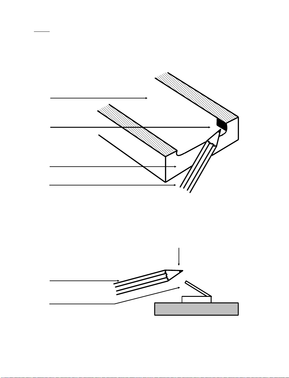
FIGURE 1
Backup battery switch
Interior view
BATTERY COMPARTMENT
BACKUP BATTERY COMPARTMENT
BOTTOM OF PTC
PEN OR PENCIL
Interior side view
PEN OR PENCIL
BACKUP BATTERY SWITCH
PUSH DOWN
18
Page 21

5. If the AFAT battery pack or the plastic case containing
batteries is in the PTC-860’s battery compartment, remove
it. Refer to the “Rem oving the batteries” section on page 44
for the correct procedure.
6. The backup battery switch is located in a small opening just
inside the batt er y compartment and to the right, when the
PTC is facedown (see Figure 1). Insert the tip of a pen or
pencil into the opening and apply dire ct pressure to push
down the switch. Make sure the switch is pressed down
completely.
7. Insert the AFAT battery pack or the plastic case containing
batteries into the PTC-860’s battery compartment. Refer to
the “Installing new batteries” section on page 45 for the
correct proce dure.
8. Replace the battery do or and tighten the two screws.
Note: If the backup battery switch ha s not be en t urne d o n, a
warning message displays when you turn on the PTC.
©
Charging the battery pack
Charge your PTC-860’s AFAT nickel-ca dmium battery pack, i f
used, before you use the unit for t he fir s t t im e and whenever
the battery pa ck becomes wea k . T h e P T C -860’s lo w-battery
light glows wh en the battery pack is low.
Note: If you are using alkaline batteries in your PTC-860,
replace them whe neve r t he low-battery light glows.
19
Page 22

Equipment required :
•
One battery charger for each PTC
•
An electrical outlet within 6 feet (1. 8 m eters) providing
110 volts AC in the U.S. or Canada or 220 volts AC
elsewhere
Note: If you are charging the PTC’s battery pack outside the
U.S. or Canada, you need a charger de signed for use in a
220-volt AC electrical outlet.
The PTC-860 can be recharged either by itself or with a Telxon
microprinter attached. If y ou plan to recharge the PTC with
the microprinter attached, see the instructions provided with
the microprinter.
The PTC-860’s battery pack can also be recharged by the
optional CS-860 Optical Communication Station, MCO-860
Four-Bay Cradle, or PTC-860 Fast Battery Charger. If you plan
to use one of these accessories , s ee the recharging ins t ructions
provided with that unit.
CAUTION! Do not charge a PTC-860NI’s ba ttery pack in a
hazardous location. Accessories are ap proved f or us e with
the PTC-860NI only in non-hazardous locations.
1.Make sure the PTC is off.
2.Disconnect all accessories from the PTC.
3.Line up the 25-pin connector on the charge r’s cable with
the connector on the PTC and push them together.
CAUTION! Do not force the connectors together if they do
not connect easily. You could be nd the p ins on the c able
connector.
If the connectors do not go together easily, check to make
sure they are lined up correctly, w id e ends on the same
side, and no pins are bent on the cable co nnec to r.
20
Page 23

4. Plug the charger into the wall outlet. The green c har ging
indicator above the display lights.
5. Charge the PTC’s battery pa ck for 14 hours.
©
Checking the PTC-860
1. Press the ON/OFF key to turn on the PTC.
2. Look at the PTC’s display. What appears on the display
depends on the pr ogram your organizati on us es.
If the PTC is operating correct ly, you should not see any of
the following:
•
A low-battery warning
•
A backup battery warning
•
A blank display screen
Repeat the steps in t his s e ction if the PTC-860 is not
operating properly. You should not hear any beeps warning
you that an error has occurred. If you do hea r wa rni ng
beeps, refer t o the “Tr oubleshooting” sectio n on page 49 or
contact your Telxon service representative.
21
Page 24

ÄÄ
arts
P
©
©
Figure 2 shows the parts of the PTC-860.
25-pin connector
On the top of the PTC is a female RS-232-type 25-pin connector
for access or i es and communic ation. A cable or the connector on
the bottom of so me accessories plugs into this connector to
communicate with the PTC. The 25-pin connector can also be
used to attach the P T C ’s battery charger.
The connector is between a sl ot, a screw, and a latch plate,
which are used to hold accessories in place when they are
connected directly to a PTC.
Application flash EPROM
An application flash E P ROM is an electronic component
soldered into the PTC-860. It contains the PTC’s data collection
program and determines the PTC’s key functions, the display
prompts and messages, and how and w hen the PTC prints or
transmits data.
You can erase the application flash EPROM and then
reprogram it with a new program from the host via software in
the PTC’s operating system.
For instructions on how to erase and reprogram an application
flash EPROM, refer to the Guide to the FLASH Utilities (TCAL
or MS-DOS Version). See Appendix B for this manual’s part
number.
CAUTION! Do not attempt to erase or reprogram the
PTC-860NI’s application flash EPROM in a hazardous
location. This procedure is approved for use only in a
non-hazardous location.
22
Page 25

©
Backup battery
All models of the PTC-860 have a built-in backup battery. The
backup battery provides enough power to pr otect data stored in
the PTC’s memor y when t he m a in batteries are being changed
or if they run out of power.
A switch inside the PTC, accessible through the ba tt er y door,
lets you turn on the backup battery. The PTC-860 is shipped
from the factory with this switch turned off to conserve the
backup battery power.
Note: Once you turn on the backup battery by pushing down
on the backup battery switch, do not attempt to reraise the
switch. It is meant to stay down permanently.
If your PTC shows a “Backup Battery Fault” message when
you turn on the PTC, either turn on the backup battery or
have the backup battery replaced. (Do not attempt to repl ac e
the backup battery yourself; contact your Telxon service
representative for assista nce!)
CAUTION! Do not store a PTC-860 for ov er two m onths
without charging the battery pack or rep lacing the alkaline
batteries. O the rw ise, both the prima ry batteries and the
backup battery w ill drain, and any data and programs
loaded in the PTC’s memory will be lo s t.
©
Bar-code reader (optional)
The PTC-860 unit (not including the PTC- 86 0ES and
PTC-860NI units ) m a y have an optional bar-code reader
that plugs into the w and port on the side of the unit . I f your
PTC-860 unit was ordered with a pencil-wand bar-code reader,
it has a holder for the reader attached to its side.
Bar-code reader s ar e available for the PTC-860ES and
PTC-860NI but must be connec te d t o t he uni ts t hrough the
25-pin connector.
23
Page 26

FIGURE 2
Parts of the PTC-860
25-PIN CONNECTOR
OPTICAL COUPLER
BATTERY RECHARGE POST
ELASTIC STRAP
DISPLAY
KEYBOARD
WAND PORT
BATTERY COMPARTMENT
24
Page 27

CAUTION! Do not use a bar-code reader with a PTC-860NI
in a hazardous location. Accessori es are ap proved for use
with the PTC-860NI only in non-hazardous locations.
The bar-code reader lets you enter data into your PTC by
passing the reader across bar- co de labels (scanning). Your
PTC’s data collection program determines the types of bar-code
labels you can read.
©
Battery charger
The battery charger is used to recharge the nickel-cadmium
battery pack in the PTC. The charger for the PTC-860 has a
25-pin connector.
CAUTION! Do not charge a PTC-860NI’s battery pack in a
hazardous locati on. Acces so ri es ar e appr oved f or use w ith
the PTC-860NI only in non-hazardous locations.
©
Battery compartment
The PTC-860 and PTC-860ES come from the factory with an
AF AT nickel-cadmium battery pack or four AA alkaline
batteries in a pl as tic battery case. The PTC-8 60NI comes with
the AFAT nick el- cadm ium b atte ry pack .
The battery pack charges in 14 hours.
When the battery pack or alkaline batteries are weak but not
weak enough to stop th e PTC f ro m operating, a low-batte ry
message displays, the PTC’s beeper sounds a warning beep,
and the red low-battery light comes on.
Note: When the PTC’s battery pack or alkaline batteries
become too weak to operate the PTC, the unit automatically
shuts off. In this event, charge the battery pack or replace the
alkaline batteries im mediately.
CAUTION! Do not store a PTC-860 for ov er two months
without charging the battery pack or rep lacing the alkaline
batteries. Otherwise, your data and programs will be lost.
25
Page 28

©
Battery recharge posts
The battery recharge posts, one on each side of the optical
coupler, make contact with spring-loaded posts on an optical
communication cradle and are used to recharge the PTC’s
nickel-cadmium battery pack.
©
Display
The PTC-860’s display screen shows the information you type
or scan into the PTC and messages and instructions from the
PTC or the host computer. The screen is a supertwist liquid
crystal dis play (LCD).
The display can show up to sixteen lines of information, each
line sixteen or twenty-one characters long. In addition, the
display is graphics supported, which allows a variety of
character sets to be displayed and e nables the 16-line di s pl a y
to emulate an 8-line disp lay.
Above the display ar e t w o light-emitting diode (LED)
indicators. The green LED glows when the battery pack is
being charged. The red LED glows when the batteries are low .
The low-battery LED wor k s only when the PTC is turned on.
©
Elastic strap
A wid e e lastic strap on the back of the PTC i s used as a hand
strap. It secures the PTC to the palm of your hand , m aking it
easier to hold onto the PTC whe n you are using it.
©
Keyboard
The keyboard on the PTC-860 can have fifty, forty , or
twenty-four ke y s. Each keyboard has two different types
of keys: data keys and function keys.
26
Page 29

Data keys are the let ter and num ber keys, A-Z and 0-9. You use
them to type da ta into the PTC. Funct ion keys include the
F1-F5, CLEAR, ENTER/YES, and SEND keys. These keys may
have different labe ls on your PTC. They are used to perfor m a
special procedure or function. For example, your program may
use the SEND function key to transmit the PTC’s data to the
host computer.
ENTER/YES key
How you use the ENTER/YES key depends on your
organization’s data collection program. Usually you press this
key to tell the program that you have finished typing data,
have finished an operation, or want the PTC to begin an
operation, such as sending data to the host computer.
ON/OFF key
Pressing this key turns the PTC on or off.
SHIFT key
On a 50-key keyboard, the SHIFT key activates only the
function keys labe le d on an overlay that slips over the
keyboard. The numeric keys are always available.
On a 40-key or 24-key keyboard, the SHIFT key shifts between
the numeric and alphabetic ke ybo ar d a nd a lso ac tivates some
of the function keys your pr ogram uses. These keys are labeled
on the overlay.
Note: Your data collection program may turn off certain keys
at times during the program to prevent you from accidently
erasing data or end ing an operation. The PTC beeps whe n you
press a key the program has turned off.
27
Page 30

©
Keyboard overlay
The keyboard over lay is a small sheet of plastic cut out to fit
over the PTC’s keyboard. Labels for the s p ec ial function keys
used by your orga nization’s data collection progra m are printed
on the overlay.
©
Optical coupler
On the back of the PTC-860 is a small red window. Behind the
window are five LEDs that the PTC can use to com m uni cate
with your host computer. Instead of sending data in the form of
electronic signals through the RS -2 32 connector, the PTC sends
the data in the form of pulses of light to a similar coupler on an
optical communication cradle. The cr adle then converts the
pulses of light into electronic signals and transmits them
directly to the ho st computer or over the phone lines. The
cradle can also send data to the PTC via the optical couplers.
©
Screwdriver
A small screwdriver is part of the cl as p on the ends of the
elastic strap. Use the screwdriver to loosen the screws holding
the battery door in pla ce when you need to change the batteries
in the PTC-860.
©
Wand port (PTC-860 only)
Optional bar-code readers plug into a wand port on the side of
the PTC-860 unit. (PTC-860ES and PTC-860NI uni ts d o no t
have a wand port.) If your PTC-860 unit was ordered without a
bar-code reader, a plastic plug covers this port. Do not remove
the plastic plug except to add a bar- code reader to your
PTC-860 unit. (For instructions on how to attach a bar-code
reader to your PTC-860 unit , see page 33.)
28
Page 31

ÄÄ
eatures
F
©
©
Automatic off
To conserve battery power, the PTC-860 turns itself off
automatically after approximately 1 minute of inactivity. The
exact length of tim e depends on the progra m .
Automatic return at on
When you turn the PTC-860 off (or when the PTC-860 turns
itself off), it remembers where it was in the data collection
program. Then, when you turn the PTC-860 back on, it returns
to that same point in the program. You do not need to review
what you have done or perform any o the r st ar t-up function to
find your place.
©
Backlight
The backlight lights up the display to make information
readable in low l ight . The backlight may or may not be
available to you, depending on your or gani zat io n’s data
collection program.
If the backlight is available, you can turn it on by pressing a
key on the PTC’s keyboard, typing in a command, or making a
choice from a list on the PTC’s screen. Once it is turned on, it
turns itself off af ter a predetermined a mount of time to
conserve battery life.
29
Page 32

©
Beeper
The PTC-860’s internal beeper is used by the PTC and your
data collection program to warn you of problems or to prompt
you to take an action. For example, if your program has
temporarily turned off a key, the PTC beeps if you press it.
©
Clock
The PTC-860’s built-in clock keeps tra ck of the date (month,
day, year, and day of the w eek) and the time (ho u rs , minutes,
and seconds). The clock operates continuo usly.
How the clock is used depends on y our data collection program.
For example, the PTC-860 can use the clock to sh ow the date
and time on its display or to direct a printer to place a time
stamp on a report.
©
Memory
The PTC-860’s internal memory stores yo ur organization’s data
collection prog ram and the data you type into the PTC.
The amount of mem ory in your PTC determines how much
data you can type in befor e yo u have to send it to a host
computer or print it. Various amounts of memory are available
from Telxon, and the amount actually installed in your PTC
has been determined by your organization’s needs.
©
Power backup system
The PTC-860 contains a lithium cell that is use d a s a b ac k up
energy source when the m a in batteries are removed or are too
weak to provide adeq uat e p owe r. If used continuously, the cell
lasts twenty days. If the main batteries are always left in the
PTC and charged, the cell has a minimum five-year life.
30
Page 33

ÄÄ
onnecting
C
accessories
Many accessories are a vailable for the PTC-860. These include
printers, adaptors, modems, and bar-code readers. All
accessories connect to the PTC-860ES and PTC-860NI through
the 25-pin connector. Bar-code readers can be connected to the
PTC-860 through a wand port on t he uni t’s side.
Some accessories plug directly into the 25-pin connector on the
PTC; some require a cable between the PTC and the accessory.
The same general proced ure is used to connect accessories and
cables.
CAUTION! Do not connect an accessory to or use an
accessory with a PTC-860NI in a hazardous location.
Accessories are ap proved for use with the PTC-860N I
only in non-hazardous locations.
©
Connecting an acces so ry
Through the 25-pin connector
The PTC-860 has three accessory fasteners: a latch plate, a
locking screw, and a slot. See Figure 3.
1. Turn off t he PTC- 860.
2. If the accessory has a locking tab, find the slot and locki ng
screw on the back of the PTC, near the top, and loosen the
screw . See Figure 3.
31
Page 34

FIGURE 3
Accessory fas tener s
LATCH PLATE
LOCKING SLOT
LOCKING SCREW
3. If the accessory uses a locking latch, find the la tc h pl at e on
the top of the PTC. The latch pl at e has a keyhole-shaped
opening in it. Note which side the wider part of the opening
is on. See Figure 3.
Locate the sliding latch button on the bottom of t he
accessory; the n locate the locking la tch on the front of the
accessory and s lide it into the open pos ition (to the left). See
Figure 4.
4. If you are connecting an accessory directly to the PTC,
insert the access or y ’s tab into the slot on the PTC and line
up the sliding butt on on the bottom of the acc essory with
the wider end of the keyhole in the PTC’s latch plate.
If you are connecting a cabl e, l ine up the connector on the
cable with the 2 5 - pi n co nnector on the PTC.
5. Gently slip the connector o n the accessory or cable o v er the
connector on the PTC and press them together. Do not use
a rocking or twisting motion when pressing the connectors
together.
CAUTION! Do not force the connectors together if they
do not connect easily. You could bend the pins on t he
accessory’s or cable’s connector.
32
Page 35

FIGURE 4
Using the accessory locking latch
6. If you are connecting an accessory directly to the PTC,
tighten the PTC’s locking screw and slide the accessory’s
locking latch as far to the right as it will go to lock the
accessory onto the PTC.
If you are connecting a cabl e, c onne ct the other end to the
accessory using the same procedure.
LOCKING LATCH
Through the wand port (PTC-860 only)
1. Before attaching a bar-code reader to the PTC-860, remove
the protective p lug from the wand port by placing the tip of
a small screwdriver between the plug and the PTC and
gently prying the plug from its port.
2. Line up the bar-code reader plug with the PTC-860’s wand
port and press the plug into the port until it snaps into
place.
33
Page 36

©
Removing an accessory
From the 25-pin connector
1. Turn off t he PTC- 860.
2. T o r emove an accessory that connects directly t o the PTC,
slide the accessory’s locking latch as far to the left as it will
go and loosen the PTC’s lo cking screw.
3. Pull the accessory or the cable’s connector directly away
from the PTC’s 25-pin connector.
Do not pull at an angle.
Do not use a rocking or twisting motion when pulling the
connectors apart.
From the wand port (PTC-860 only)
1. To remove a bar-code reader from the PTC-860, insert the
tip of a pen or pencil into the openin g at the top of the
bar-code reader plug and press down firmly. (A release on
the plug should be activated, allowing the plug to be
removed.)
2. Firmly pull the bar-code reader plug from the wand port.
3. Replace the wand port’s protective plug.
34
Page 37

ÄÄ
canning
S
bar-co de labels
Follow this procedure if you are scanning labels with a
pencil-wand bar-code reade r. If you are using another type of
reader, see the instructions shipped with the reader.
1. Place the tip of the b ar-code reader to the left or right o f t h e
bars on the bar-code label. Make sure the reader touches
the label and is within 30 degrees of vertical in any
direction.
2. Draw the bar-code reader across the label with a smooth,
quick motion. The PTC beeps when the reader succes s ful ly
reads a label.
Note: Do not draw the reader across the label too slowly.
More scanning failures occur fro m scanning too slowly than
from scanning too quickly.
If the bar-co de reader fails to read the label, the label may
be dirty. Wipe off the lab el and try again.
If the bar- code reader still fails to read the label, try
scanning across the top or bottom of the bars in the bar
code. If neces sary, wipe off the tip of the bar-code reader.
35
Page 38

ÄÄ
ommunicating
C
data
The PTC-860 is able to communicate w i th other computers and
PTCs. How it communicates and how it i s connected depends
on your data collection program and how your PTC-860 is
equipped.
The PTC-860 can be set up for either one-way or two-way
communication. It can communicate through its optical coupler
or through its RS-232-type 25 -pin c onne ct or.
The PTC-860 can b e connected directly to a host computer or
another PTC, or it can be equipped wit h an optional modem to
communicate over telephone lines.
©
Using the optical coupler
The PTC-860 has an optical coupler on the back of its unit. The
optical couple r c onverts electronic signals inside the PTC into
pulses of light that can be detected by the CS-860 Optical
Communication Stati on o r t he M CO-8 60 Four-Bay Cradle.
When the PTC-860 is placed in a cradle, an optical coupler on
the cradle senses the pulses of light from the PTC and converts
them into electronic signals for direct communicat ion to the
host computer or, with an external modem, for transmission
over telephone lines.
Likewise, the cr adle can communicate back to the PTC through
the optical couplers.
36
Page 39

Communicating through the o pt ic al coupler requires the use o f
an optical communication cradle. See the Guide to the CS-860
Optical Communication Station or the Guide to the MCO-860
Four-Bay Cradle for instructions.
CAUTION! Do not use a PTC-860NI with a CS-860 or an
MCO-860 in a hazardous location. Accessories ar e approved
for use with the PTC-860NI only in non-hazardous
locations.
©
Using the 25-pin connector
To connect the PTC-860 to another computer or PT C v ia the
25-pin connector, you need the correct cable. Different cables
may be required dependi ng on w hat yo u ar e connecting the
PTC to. See the manual or instruc ti ons yo ur o rganizati on
supplies for your data collection program.
Connecting a cable
1.Make sure you have the correct ca ble for t he device you are
connecting to. If you use the wrong cable, the PTC may not
be able to communic ate.
2.Turn off the PTC.
3.Line up the connector on the cable wit h the connector on
the PTC. The pins on the cable’s connector fit into the holes
in the PTC’s connector.
4.Gently slip the connector on the cable over the connector on
the PTC and press them together. Do not use a r oc king or
twisting motion when pressing the connectors together.
CAUTION! Do not force the connectors together if they do
not connect easily. You could be nd the p ins on the c able ’s
connector.
5.Connect the other end of the cable to the computer or other
PTC.
37
Page 40

6. Turn on the PTC and then turn on the device it is
connected to.
7. To communicate, follow the instructions for your data
collection program.
Disconnecting a cable
CAUTION! When removing the cable from the PTC or
other device, grasp the cable connector head to remove the
cable. Pulling on the cable can break the wiring from the
cable connector.
1. Turn off t he PTC- 86 0 .
2. Turn off the other computer or PTC.
3. Pull the cable’s connector directly away from the PTC’s
25-pin connector.
Do not pull at an angle.
Do not use a rocking or twisting motion when pulling the
connectors apart.
©
Cloning
Cloning is a method for sending copies of data or programs
from one PTC to another. The specific keys to press, the
sequence to follow, and the prompts that display vary according
to your applicatio n. Ther ef or e, t h is p ro ce dur e d es cribes only
the general process of cloning. Refer to your individual
application docum e ntation for specific instructions.
Before beginning the cloning procedure, be sure both PTCs are
fully charged. If either PTC turns off during the cloning
operation, you must start the procedure again. In addition, you
should monitor the cloning proced ure from start to f ini sh. At
some points, the procedure requires action from you.
The primary PTC contains the data or program to be cloned.
The secondary PTC receives the program or data.
38
Page 41

1. Perform any preparations for cloning.
2. Connect a clone cable to the 25-pin connector on the
primary PTC an d t o the 25-pin connector on the secondary
PTC.
3. Follow your application’ s c lo ning p ro ce dure.
4. When the data or program has been cloned successfully,
disconnect the clone cable from both PTCs.
39
Page 42

ÄÄ
M
©
aintaining
the PTC-860
Operating conditions
Each of the PTC-860 optical models can be operated at
temperatures between –20 d egrees F (–29 degrees C) and 120
degrees F (49 degrees C).
PTC-860
The PTC-860 unit is designed to operate in environments that
are normally free of dust, dirt, and moisture.
PTC-860ES
The PTC-860ES is designed to work in rugged environments. It
has been specially sealed to resist dus t, dirt, and moisture.
CAUTION! Although the PTC-860ES unit is designed to
operate in rugged envir onm ents, the available accessori es
are not. Do not operate a PTC-860ES with any at tache d
accessories in excessively dusty, dirty, or moist conditions.
PTC-860NI
The PTC-860NI is designed for use in hazardous locations.
(Refer to the “Use in hazardous locations” section on page 9 for
information on the locations in which the unit is approved for
use.)
40
Page 43

CAUTION! Do not operate a PTC-860NI with any
attached access orie s in a ha zar dous loca ti on. A cce ss orie s
are approved for use with the PTC-860NI only in
non-hazardous locations.
©
Handling the PTC-860
The following information can help to ensure you re ce ive
reliable, trouble-free service from your PTC- 860.
•
Do not open the PTC-860’s case. Only a trained techni cian
can service the parts inside the PTC’s case.
•
If you store a PTC-860 containing a nickel -cad mium battery
pack in below-freezing temperatures for more than 1 hour,
do not charge the battery pack until it warms up to room
temperature.
•
Make sure the PTC-860 is off before you connect or remove
any accessor ies or replace the bat teries.
•
Make sure all ac cessories connected b y cable are connected
correctly and all accessories are locked into place.
•
Do not connect or use any acce ssor ie s wit h a PTC-860NI in
a hazardous location.
•
Use only an AFAT nickel-cadmium battery pack in the
PTC-860NI.
•
Use only Telxon-approved batteries and accessories. Do not
attempt to connect any electrical device that is not part of
your PTC-860 system to the PTC-860.
•
Protect the PTC-860 from excessive heat, cold, and
moisture and from harsh, dirty environments.
•
Do not insert anything into the 2 5-pin connector.
•
Do not remove a ny of the rubber or plastic plugs on the
PTC-860’s case, except to add a bar -c o d e reader.
41
Page 44

©
Storing the PTC-860
CAUTION! Do not store a PTC-860 for ov er two m onths
without charging the battery pack or replacing the alkaline
batteries. Otherwise, bot h the primary batteries and the
backup battery will drain, and any data or programs loaded
into the PTC’s memory wi ll be lost.
•
Do not store the PTC-860 i n temperatures below –20
degrees F (–29 degrees C) or above 160 degrees F (71
degrees C).
•
Do not store the PTC-860 i n a d a m p or humid environment.
1.Transfer any data stored in the PTC to a host computer or
another PTC or print the data. See the manual or
instructions for your organization’s data collection program
for information.
2.Make sure you have a copy of any program s sto re d in the
PTC.
3.Disconnect all accessories from the PTC.
4.Recharge the PTC’s battery pack or replace the alkaline
batteries.
5.Pack the PTC in the original packing material or in a
padded box and put the PTC in a sa f e place, away from
dust, dirt, humidity, and excessive cold.
©
Cleaning the PTC-860
CAUTION! Do not soak the cloth used to wipe the PTC-860
and do not spray or pour cleaning liquids directly onto the
PTC.
To clean the PTC-860, slightly moisten a soft, c le an, l int -free
cloth with a mild, nonabr asi v e c leaner and wipe the outside
surface.
To clean the PTC-860’s display, slightly moisten a soft, clean,
lint-free cloth with a mild glass cl eaner and wipe.
42
Page 45

Do not use a paper tow el on any part of the PTC-860, including
the display.
If the PTC-860 become s extremely dirty or if liquids , dirt, or
other foreign materials get inside the case, contact your Telxon
service representative.
©
Servicing the PTC-860
Do not attempt to service the PTC. Only a trained Telxon
technician may ser vice the PTC.
43
Page 46

ÄÄ
eplacing
R
the batteries
The PTC-860’s AFAT nickel-cadmi um batter y pack or AA
alkaline batteries may be replaced when necessary .
CAUTION! Do not remove or install a PTC-860NI’s
battery pack i n a hazardous location. These procedures
are approved for use with the PTC-860NI only in
non-hazardous locations.
Note: Once you remove the PTC’s batteries, the backup
battery, if used continuously, will protect stored programs and
data for up to tw enty days. If you do not replace the batteries
within that time, your PTC’s stored programs and data will be
lost.
Equipment req uir ed:
•
A small scre wdriver or the scre w driver on the
PTC-860’s elastic strap
©
Removing the batteries
1. Turn off t he PTC.
2. Lay the PTC facedown, with the bottom toward you.
3. Locate the battery door and the two screws securing it.
4. Unscrew the two screws us ing the small screw dr iv e r.
Note: Do not remove the screws from the battery door. The
screws are designed to stay in the door when it is removed
from the PTC.
44
Page 47

5. Lay the battery door facedown on your work surface. The
gasket on the inside of the door should be facing up.
CAUTION! Keep the gasket and the inside of the batter y
door clean and free of dust and dirt. Dust or dirt on the
gasket could keep it from sealing properly.
6. Pick up the PTC.
7. Hold your free hand near the bottom of the PTC and tilt the
unit so the nickel-cadmium battery pack or battery case
with AA al kaline batt erie s slides out into yo ur ha nd. You
may have to gently shake the PTC to get the battery pack
or case to sl ide out.
8. Tilt the battery case to slide out the old batteries.
©
Installing new batte r ie s
AFAT nickel-cadmium batter y pack
1. Locate the + sign molded into the PTC ne ar the battery
compartment opening.
2. Examine the AFAT nickel-cadmium battery pack. Locate
the + sign printed on the battery pack.
FIGURE 5
Inserting a battery pack
STRAIGHT EDGE OF
BATTERY PACK
45
Page 48

3. Make sure the + sign on the battery pack is on the s ame
side as the + sign on t he PTC and the straight edge of the
battery pack is facing up (see Figure 5 ); then insert the
battery pack directly into the bottom of the PTC.
The battery pack has a spacer to prevent it from being
inserted incorre ct ly.
4. Pick up the battery door and look at the gasket on the
inside. Make sure the gasket is clean of dust and dirt. If
necessary, wipe it with a soft cloth.
5. Hold the battery door so the rounded corners are at the
bottom. The battery door will fit in place only if the rounded
corners are even with the back of the PTC.
6. Place the battery door over the opening in the bottom of the
PTC and line up the screws with the holes in the PTC.
7. Tighten the screws that hold the battery door in place.
Tighten them until the y ar e snug but not more.
8. Turn on the PTC. It should not display any warning
messages if the b at tery pack has been inserted pr op erly
and is charged.
AA alkaline batteries
CAUTION! Do not attempt to insert AA nickel-cadmium
batteries into the plastic battery case. The case is designed
for use with only AA alkaline batteries.
CAUTION! Do not attempt to use alkaline batteries in
the PTC-860NI. This unit is designed for use with only an
AFAT ni ck el-cadmium battery pack.
1. Hold the battery case in your hand with the battery
outlines molded in the plastic facing up .
2. Insert the batteries into the plastic battery case, making
sure they match t he orientation of the polarity marks (+, -)
molded on the case. See Figure 6.
46
Page 49

FIGURE 6
Inserting AA alkaline batteries
into the plastic battery case
3. Hold the battery case in one hand with the opening up and
the polarity m arks facing you.
4. Insert the battery case, open end first, into the battery
compartment.
CAUTION! Do not force the battery case into the battery
compartment. A raised tab on the left side of the battery
case prevents the case from being inserted incorrectly.
5. Pick up the battery door and look at the gasket on the
inside. Make sure the gasket is clean of dust and dirt. If
necessary, wipe it with a soft cloth.
6. Hold the battery door so the rounded corners are at the
bottom. The battery door will fit in place only if the rounded
corners are even with the back of the PTC.
7. Place the battery door over the opening in the bottom of the
PTC and line up the screws with the holes in the PTC.
8. Tighten the screws that hold the battery door in place.
Tighten them until the y ar e snug but not more.
9. Turn on the PTC. It should not display any warning
messages if th e batteries have been ins erted properly and
are new.
47
Page 50

Backup battery
Under average conditions, the backup battery will last a
number of years. When the backup battery fails, a warning
message displays on the PTC’s screen.
Because the backup battery is attached to one of the internal
circuit boards, it can b e r eplaced only by a trained Telxon
service engineer. Send the PTC to a Telxon service depot to
have the backup battery replaced.
48
Page 51

ÄÄ
roubleshooting
T
©
The PTC does not turn on
•
Charge or replace the nickel-cadmium battery pack or
replace the alkaline batteries.
©
The bar-code reader fails to read a label
•
Try scanning across the top or bottom of the bars on the
label.
•
Make sure the bar-code read er is connected securely to the
PTC.
•
Wipe off the bar-code label.
•
Wipe off the tip of the bar-code reader.
©
The PTC shows a “Backu p Battery Fault” message when you turn it on
•
Turn on the backup battery .
•
Make sure the backup battery switch is pressed down
completely .
•
Have the backup batter y re placed by a trained Telxon
technician.
©
Other problems or difficulties with your PTC-860
•
Notify your Telxon service representat ive or contact the
Telxon Customer Support Center at 1-800-800-8010.
49
Page 52

ÄÄ
ppendix
A
©
Specifications
Electrical
Data communications
via 25-pin connector: Full duplex, 30 0 to 19.2 K bits pe r s econd
Power: Four-cell AFAT nickel-cadmium battery
Charger input
voltage requirement: 12 VDC 200 mA
Environmental
Operating temperature: –20 to 120 degrees F
A
pack, 800 mAhr
Four AA alkaline batteries, 1500 mAhr
(not for PTC-860NI use)
(–29 to 49 degrees C)
Storage temperatur e: –20 to 160 degr ee s F
(–29 to 71 degrees C)
Operating humidity: 95% noncondensing
100% (PTC-860ES)
Physical
Length: 8.65 in/22 cm
Width (keyboard): 3.3 in/8.4 cm
Width (display): 3.5 in/8.9 cm
Depth: 1.7 in/4.3 cm
50
Page 53

Weight:
(w/ AFAT battery pack) 25.5 oz/.7 kg
(w/ AA batteries) 24 oz/.68 kg
51
Page 54

ÄÄ
ppendix
A
©
Hardware part numbers
The following table contains part numbers for ordering
accessory hardware for the PTC-860 optical models.
TABLE 2
Hardware part numbers
B
Item Part number
Batteries
Plastic battery case
Alkaline batteries
AFAT nickel-cadmium
battery pack
Battery charger
PTC-860 Fast Battery Charger
with cycling
without cycling
15527-001
07301-000
14861-000
15227-000
15618-001
15618-002
Bar-code readers
Pencil wands
6 mil VR
6 mil IR
10 mil VR
10 mil IR
Laser diode scanner
HeNe scanner
09840-824
09840-805
09840-806
09840-807
See *
See *
52
Page 55

Item Part number
Printers
IP-24 Microprinter
MP-830 Microprinter
24-column version
24-column version kit
42-column version
42-column version kit
RM-80 Printer
Adaptors
BCM-6
TBM-160
Modems
TCM-100
TCM-212R
TCM-224**
Cradles
CS-860 Optical Communication
Station
w/o mounting hardware
w/ table mount hardware
w/ wall mount hardware
MCO-860 Four-Bay Cradle
w/o a modem
w/ a 202 modem
w/ a 212/224 modem
w/ a 224MV modem
16603-102
16489-000
16489-700
16489-003
16489-703
16406-004
12664-001
10854-001
10095-202
11231-100
14580-00X
14816-000
14816-001
14816-002
15934-000
15934-001
15934-002
15934-003
53
Page 56

Item Part number
Cables
PTC-to-IBM PC/AT cable***
PTC-to-IBM PC/XT cable****
Clone cable
PTC-to-1/2 duplex modem
cable***
PTC-to-full duplex modem
cable***
PTC-to-host (DTE) cable***
Manuals
Guide to the FLASH Utilities
(TCAL or MS-DOS Version)
Guide to Maintaining NiCd
Batteries
Guide to the PTC-860 Fast
Battery Charger
Guide to the CS-860 Optical
Communication Station
Guide to the MCO-860
Four-Bay Cradle
13656-3X0
10582-XX0
09944-001
10124-0X1
10124-0X2
10124-0X3
16541-000
16488-000
16014-000
15124-000
16125-000
* Contact your Telxon sales representative t o obtain part
numbers for these products.
** The last digit of the TCM-224 modem part number indicates
the country in which the modem is to be used. A 0 indicates
use in the U.S., and a 1 indicates us e in Canada.
*** The middle digit in the last three numbers of these cable
part numbers indicates the cable length in feet. You may
adjust these number s according to your requireme nts .
**** The first and second digits in the last three numbers of
this cable pa rt number indicate wh et her the connector is
male (010 or 110) or female (000).
54
Page 57

ÄÄ
ppendix
C
A
©
Communication connections
Figures 7 through 12 provide information on the connections
used to establish and m aintain communication b et w een the
PTC-860 and other devices.
FIGURE 7
PTC-to-IBM PC/AT cable, P/N 13656-3X0
PTC-860 IBM PC/A T
TXD 2 2 RXD
RXD 3 3 TXD
CTS 5 4 DTR
GND 7 5 GND
RTS 4 6 DSR
DSR 6 7 RTS
DTR 20 8 CTS
–5 10 9 RI
OUT 11 1 CD
55
Page 58

FIGURE 8
PTC-to-IBM PC/XT cable, P/N 10582-XX0
PTC-860
Male
TXD 2 3 RXD
RXD 3 2 TXD
RTS 4 6 DSR
CTS 5 20 DTR
DSR 6 4 RTS
GND 7 7 GND
DTR 20 5 CTS
–5 10
OUT 11
IBM PC/XT
Female (0 00)/
Male (110)
56
Page 59

FIGURE 9
Clone cable, P/N 09944-001
PTC-860 A PTC-860 B
DTR 20 20 DTR
DSR 6 6 DSR
RTS 4 4 RTS
CTS 5 5 CTS
TXD 2 3 RXD
RXD 3 2 TXD
OUT– 11 11 OUT–
BAT– 7 7 BAT–
GND 1 1 GND
57
Page 60

FIGURE 10
PTC-to-1/2 duplex modem cable, P/N 10124-0X1
PTC-860
TXD 2 2 TXD
RCV 3 3 RCV
DSR 6 6 DSR
DTR 20 20 DTR
RTS 4 4 RTS
CTS 5 5 CTS
RI 22 22 RI
CD 8 8 CD
SG 7 7 SG
–5 10
OUT 11
MOD 202/Type I
(1/2 Duplex)
58
Page 61

FIGURE 11
PTC-to-full duplex modem cable, P/N 10124-0X2
PTC-860
TXD 2 2 TXD
RCV 3 3 RCV
DTR 20 20 DTR
DSR 6 6 DSR
RI 22 22 RI
CD 8 8 CD
SG 7 7 SG
RTS 4
CTS 5
–5 10
OUT 11
MOD 212/Type II
(Full Duplex)
59
Page 62

FIGURE 12
PTC-to-host (DTE) cable, P/N 10124-0X3
PTC-860
RXD 3 2 TXD
TXD 2 3 RXD
DTR 20 6 DSR
DSR 6 20 DTR
RTS 4
CTS 5 8 CD
CD 8 5 CTS
SG 7 7 SG
Host/T ype III
(Full or 1/2
Duplex)
4RTS
OUT 11
–5 10
60
Page 63

ÄÄ
lossary
G
alphanumeric
application
application
flash EPROM
bar code
bar-code
reader
CD
character
cloning
Describes a character set that contains letters, numbers, and
symbols such as punctuation marks.
A PTC program that is designed to perform a specific task for
the user. Examples include route accounting, payroll, price
lookup, shipping, and inventory control.
An electronic component soldered into a PTC that contains
the unit’s data collection program. It can be erased and
reprogrammed while in the PTC.
A series of vertical bars and spaces used to encode numeric or
alphanumeric information. Bar codes are designed to be read by
electronic means such as bar-code readers or laser scanners.
An electrical device designed to recognize and decipher bar-code
labels. When the reader passes over the bar code, it converts the
bar code into electrical signals representing data. The PTC can
then enter this data into files in its memory.
Carrier detect signal. CD indicates that the mode m is receiving
a signal from the remote modem.
A letter, number, or symbol.
The process of copying a program or data files from one PTC
directly to another.
CTS
data
communication
DCE
Clear-to-send signal. CTS indicates that the line between a
modem and a terminal device is clear for transmission. CTS
typically follows a raised request-to-send (RTS) signal.
The transport of encoded information from one point to another.
Data communications equipment. A device that controls and
converts incoming data or communication. For example, a
modem.
61
Page 64

display
The LCD screen on the front of the PTC. It shows data entered
into the PTC and warning prompts.
DSR
DTE
DTR
function key
hardware
host
computer
keyboard
overlay
LCD
LED
Data set ready signal. The modem sends DSR to the attached
device to indicate that the modem is connected, on, and ready.
Data terminal equipment. A device comp risin g the data so urce.
For example, the host computer.
Data terminal ready signal. The signal sent by the terminal
device to the modem to indicate that the terminal is ready for
transmission.
A key on the PTC’s keyboard that is defined by an application to
perform a specific task. When pressed, a function key executes a
certain function (for example, ENTER, END, ON/OFF).
Equipment used in conjunction with programs or data
communication. Compare with software.
A personal computer or mainframe that receives and processes
data from PTCs.
The plastic label that lies on the PTC keyboard, identifying the
function key definitions.
Liquid crystal display. The PTC-860’s display is of this type.
Light-emitting diode.
modem
MS-DOS
nickel-cadmium
battery pack
one-way
communication
Modulator-demodulator. A communication device that co nverts
serial digital data from a transmitting device to a signal suitable
for transmission over a telephone line and then reconverts the
signal to serial digital data for the receiving device.
Microsoft Disk Operating System.
A type of rechargeable battery used to power the PTC and some
of its accessories.
Transport of information from one device to another without
interruption. In one-way communication, the receiving device
cannot respond directly to the sending device.
62
Page 65

optical coupler
A device that converts electronic signals inside the PTC into
pulses of light that can be detected by an optical communication
station.
prompt
PTC
RAM
RI
RS-232
RTS
RXD
software
Messages shown by the PTC that guide the operator through
the steps of a data collection program. Prompts vary for
different programs.
Portable T ele-Transaction Computer. A battery-powered,
hand-held, programmable device used to collect, store, and
transmit data.
Random access memory. In a PTC, RAM chips store the
program’s files and data entered by the operator.
Ring indicate signal. RI alerts a modem to a call waiting on the
attached telephone line.
An Electronic Industries Association (EIA) standard that defines
the connector, connector pins, and signals used to transfer data
serially from one device to another.
Request-to-send signal. RTS initiates the data transmission
sequence on a communication line between a modem and a
terminal device.
Receive data signal. RXD indicates that a device is currently
receiving data.
A stored program or set of programs that is loaded into RAM for
execution. Compare with hardware.
TCAL
two-way
communication
TXD
Telxon Common Application Language. T elxon’s proprietary
programming language for PTCs.
Exchange of information between two devices. After each block
of data, the receiving device sends a positive or negative
acknowledgment to the sending device.
Transmit data signal. TXD indicates that a device is currently
transmitting data.
63
Page 66

ndex
I
ÄÄ
25-pin connector, 22
communicating data, 37-38
connecting an accessory, 31-33
removing an accessory, 34
A
Accessories, 15, 41
connecting, 31-33
removing, 34
used with PTC-860NI, 15
Accessory fasteners
latch plate, 22, 31-34
locking screw, 22, 31-34
slot, 22, 31-32
Adaptors, 31
part numbers, 53
Alkaline batteries, 15, 25, 50
inserting, 46-47
removing, 44-45
when weak, 19, 25, 30
Application flash EPROM, 22
Automatic off, 29
Automatic return at on, 29
B
Backlight, 29
Backup battery, 23, 44
replacing, 48
turning on, 17-19
Backup battery switch, 19, 23
Bar-code reader, 23, 25, 31
connecting, 33
disconnecting, 34
entering data, 13-14
failure to read, 35, 49
part numbers, 52
scanning, 35
Bar codes, 14
scanning, 35
Battery chargers, 20-21, 25
part numbers, 52
Battery compartment, 25
Battery recharge posts, 26
Beeper, 30
Beeps, 13, 21, 25
C
Cables, 31
connecting, 37-38
connections, 55-60
disconnecting, 38
part numbers, 54
Cautions
battery use in the PTC-860NI, 44, 46
charging a PTC-860NI’s battery
pack, 20, 25
cleaning the PTC-860, 42
connecting an accessory to the
PTC-860NI, 31, 41
disconnecting cables, 38
inserting batteries, 44
inserting batteries into the battery
case, 46
64
Page 67

inserting the battery case, 47
joining connectors, 20, 32, 37
keeping battery door clean, 45
PTC-860ES accessories, 40
reprogramming a PTC-860NI’s
flash EPROM, 22
storing a PTC-860, 23, 25, 42
using a bar-code reader with a
PTC-860NI, 25
using a PTC-860NI with a cradle, 37
Charging the nickel-cadmium battery
pack, 19-25
Charging time, 21, 25
Cleaning the PTC-860, 42-43
Clock, 30
Clone cable, 39, 54, 57
Cloning, 14, 38-39
Communicating data, 14-15, 36-39
Communication connections, 55-60
Cradles, 20, 26, 28, 36-37
part numbers, 53
CS-860, 20, 36-37
part numbers, 53
Customer Support Center
contacting, 49
D
F
FCC statement, 8
Features, 29-30
G
Green LED, 21, 26
H
Handling the PTC-860, 41
Hardware part numbers, 52-54
Host computer, 14, 28, 36
K
Keyboard, 26-27
data keys, 26-27
entering data through, 14
ENTER/YES key, 27
function keys, 26-27
number of keys, 26
ON/OFF key, 27
SHIFT key, 27
Keyboard overlay, 28
Display, 26
backlight, 29
Downloading, 14
E
Elastic strap, 26
Electrical specifications, 50
Entering data, 13-14
with a bar-code reader, 14
via cloning or downloading, 14
through the keyboard, 14
L
Latch plate, 22, 31-32
LEDs, 26
optical coupler, 28
Lithium cell, 30
Locking latch, 32-34
Locking screw, 22, 31-34
Low-battery LED, 19, 25-26
65
Page 68

M
P
Maintaining the PTC-860, 40-43
Manuals
part numbers, 54
MCO-860, 20, 36-37
part numbers, 53
Memory, 30
Messages, 13
backup battery, 21, 48, 49
low battery, 21, 25
Models of PTC-860s, 15, 16
Modems, 14, 31, 36
part numbers, 53
N
Nickel-cadmium battery pack,
15, 25, 41-42, 50
charge time, 21, 25
charging, 19-21, 42
disposing of, 12
installing, 45-46
part number, 52
removing, 44-45
when weak, 19, 25, 30
O
Operating conditions, 40-41
Operating temperature, 40, 50
Optical coupler, 28
communicating data, 36-37
Overview
of the PTC-860, 13-15
Packing material
saving, 17
using, 42
Parts, 22-28
Physical specifications, 50-51
Power backup system, 30
Printers, 20, 31
part numbers, 53
Prompts, 13
PTC-860
checking, 21
cleaning, 42-43
compared to other models, 15
dimensions, 50
entering data, 13-14
failure to turn on, 49
features, 29-30
handling, 41
items shipped with unit, 16
maintaining, 40-43
models, 15, 16
operating conditions, 40-41
operating temperature, 40, 50
overview, 13-15
part numbers, 52-54
parts, 22-28
servicing, 43
specifications, 50-51
storage temperature, 42, 50
storing, 42
unpacking, 16-17
PTC-860ES
compared to other models, 15
PTC-860NI
compared to other models, 15
responsibility for use, 9
safety information, 9-12
use of accessories, 15
use in hazardous locations, 9-12
66
Page 69

R
W
RS-232 connector, 28, 36
S
Safety information, 9-12
disposing of battery packs, 12
PTC-860NI, 9-12
Scanning, 25, 35
failures, 35, 49
Screwdriver, 28
Servicing the PTC-860, 43
Shipping damage, 17
Specifications
electrical, 50
environmental, 50
physical, 50-51
Storage temperature, 42, 50
Storing the PTC-860, 42
T
Temperatures
operating, 40, 50
storage, 42, 50
Troubleshooting, 49
backup battery fault, 49
bar-code reader failure, 49
other problems with the PTC-860,
49
PTC does not turn on, 49
Wand port, 23, 28, 31
connecting a bar-code reader, 33
disconnecting a bar-code reader,
34
Warnings, 21, 48
PTC-860NI, 10
U
Unpacking the PTC-860, 16-17
67
Page 70

Telxon Corporation/3330 West Market Street, Akron, Ohio 44334/216-867-3700/800-800-8001
Part No. 14767-701-03 Printed in U.S.A.
 Loading...