

Page 1

P470/P370 RF Scanners
Product Reference Guide
Page 2

Page 3

P470/P3 70 RF Scan n er
Product Reference Guide
72-38495-03
Revision B
December 2001
Page 4

© 2001 by S ymbol Technologies, Inc. All rights reserv ed .
No part of this publication may be reproduced or used in any form, or by any electrical or
mechanical means, without permission in writing from Symbol. This includes electronic or
mechanical means, such as photocopying, recording, or information storage and retrieval
systems. The material in this manual is subject to change without not i ce.
The software is provided strictly on an “as is” basis. All software, including firmware,
furnished to the user is on a licensed basis. Symbol grants to the user a non-transferable
and non-exclusive license to use each software or firmware program delivered hereunder
(licensed program). Except as noted below, such license may not be assigned,
sublicensed, or otherwise transferred by the user without prior written consent of Symbol.
No right to copy a licensed program in whole or in part is granted, except as permitted under
copyright law. The user shall not modify, merge, or incorporate any form or portion of a
licensed program w it h other program material, create a derivative work from a licensed
program, or use a licensed program in a network without written permission from Symbol.
The user agrees to maintain Symbol’s copyright notice on the licensed programs delivered
hereunder, and to include the same on any authorized copies it makes, in whole or in part.
The user agrees not to decompile, disassemble, decode, or reverse engineer any licensed
program delivered to the user or any portion thereof.
Symbol reserves the right to make changes to any software or product to improve reliability,
function, or design.
Symbol does not assume any product liability arising out of, or in connection with, the
application or use of any product, circuit, or application described herein.
No license is granted, either expressly or by i mpl ication, es to ppel, or ot herwise under any
Symbol Technologies, Inc., intellectual property rights. An implied license only exists for
equipment, circuits, and subsystems contained in Symbol products.
Symbol, Spectrum One, and Spectrum24 are registered trademarks of Symbol
Technologies, Inc. Other product names mentioned in this manual may be trademarks or
registered trademarks of their respective companies and are hereby acknowledged.
Symbol Technologies, Inc.
One Symbol Plaza
Holtsville, New York 11742-1300
http://www.symbol.com
2
Page 5

Contents
About This Manual
Introduction . . . . . . . . . . . . . . . . . . . . . . . . . . . . . . . . . . . . . . . . . . . . . . . . . . . . . . . . . . . . . . . . . . . .ix
Chapter Descriptions . . . . . . . . . . . . . . . . . . . . . . . . . . . . . . . . . . . . . . . . . . . . . . . . . . . . . . . . . . . . . ix
Notational Conventions . . . . . . . . . . . . . . . . . . . . . . . . . . . . . . . . . . . . . . . . . . . . . . . . . . . . . . . . . . . ix
Related Publications . . . . . . . . . . . . . . . . . . . . . . . . . . . . . . . . . . . . . . . . . . . . . . . . . . . . . . . . . . . . . x
Service Information . . . . . . . . . . . . . . . . . . . . . . . . . . . . . . . . . . . . . . . . . . . . . . . . . . . . . . . . . . . . . . x
Symbol Support Center . . . . . . . . . . . . . . . . . . . . . . . . . . . . . . . . . . . . . . . . . . . . . . . . . . . . . . . xi
Warranty . . . . . . . . . . . . . . . . . . . . . . . . . . . . . . . . . . . . . . . . . . . . . . . . . . . . . . . . . . . . . . . . . . . . . xiii
Warranty Coverage and Procedure . . . . . . . . . . . . . . . . . . . . . . . . . . . . . . . . . . . . . . . . . . . . . xiv
General. . . . . . . . . . . . . . . . . . . . . . . . . . . . . . . . . . . . . . . . . . . . . . . . . . . . . . . . . . . . . . . . . . . xiv
Chapter 1. The P470/P370 RF Scanner
Introduction . . . . . . . . . . . . . . . . . . . . . . . . . . . . . . . . . . . . . . . . . . . . . . . . . . . . . . . . . . . . . . . . . . 1-1
Rechargeable Battery . . . . . . . . . . . . . . . . . . . . . . . . . . . . . . . . . . . . . . . . . . . . . . . . . . . . . . . . . . 1-2
The Cradle . . . . . . . . . . . . . . . . . . . . . . . . . . . . . . . . . . . . . . . . . . . . . . . . . . . . . . . . . . . . . . . . . . . 1-2
Quick Startup Instructions . . . . . . . . . . . . . . . . . . . . . . . . . . . . . . . . . . . . . . . . . . . . . . . . . . . . . . . 1-3
Commonly Used P470/P370 Programming Bar Code. . . . . . . . . . . . . . . . . . . . . . . . . . . . . . . . . . 1-4
Chapter 2. Set Up
Introduction . . . . . . . . . . . . . . . . . . . . . . . . . . . . . . . . . . . . . . . . . . . . . . . . . . . . . . . . . . . . . . . . . . 2-1
Unpacking . . . . . . . . . . . . . . . . . . . . . . . . . . . . . . . . . . . . . . . . . . . . . . . . . . . . . . . . . . . . . . . . . . . 2-1
Setting Up the Cradle . . . . . . . . . . . . . . . . . . . . . . . . . . . . . . . . . . . . . . . . . . . . . . . . . . . . . . . . . . 2-1
Connecting to a Host . . . . . . . . . . . . . . . . . . . . . . . . . . . . . . . . . . . . . . . . . . . . . . . . . . . . . . . 2-1
Wall Mounting. . . . . . . . . . . . . . . . . . . . . . . . . . . . . . . . . . . . . . . . . . . . . . . . . . . . . . . . . . . . . 2-4
Pairing the Scanner with the Cradle. . . . . . . . . . . . . . . . . . . . . . . . . . . . . . . . . . . . . . . . . . . . 2-6
Optimizing RF Performance. . . . . . . . . . . . . . . . . . . . . . . . . . . . . . . . . . . . . . . . . . . . . . . . . . . . . . 2-7
Mounting. . . . . . . . . . . . . . . . . . . . . . . . . . . . . . . . . . . . . . . . . . . . . . . . . . . . . . . . . . . . . . . . . 2-7
Coexistence in Spectrum24 Environments. . . . . . . . . . . . . . . . . . . . . . . . . . . . . . . . . . . . . . . 2-7
Phaser-to-Phaser Co-Existence . . . . . . . . . . . . . . . . . . . . . . . . . . . . . . . . . . . . . . . . . . . . . . . 2-8
iii
Page 6

P470/370 RF Scanner Product Reference Guide
Charging the Battery. . . . . . . . . . . . . . . . . . . . . . . . . . . . . . . . . . . . . . . . . . . . . . . . . . . . . . . . . . . . 2-8
Using the Cradle . . . . . . . . . . . . . . . . . . . . . . . . . . . . . . . . . . . . . . . . . . . . . . . . . . . . . . . . . . . 2-9
Using the UBC 2000 . . . . . . . . . . . . . . . . . . . . . . . . . . . . . . . . . . . . . . . . . . . . . . . . . . . . . . . . 2-9
Battery Charge . . . . . . . . . . . . . . . . . . . . . . . . . . . . . . . . . . . . . . . . . . . . . . . . . . . . . . . . . . . . . . . . 2-9
Chapter 3. Operation
Introduction . . . . . . . . . . . . . . . . . . . . . . . . . . . . . . . . . . . . . . . . . . . . . . . . . . . . . . . . . . . . . . . . . . .3-1
Default Application . . . . . . . . . . . . . . . . . . . . . . . . . . . . . . . . . . . . . . . . . . . . . . . . . . . . . . . . . . . . . 3-1
Initial Powerup . . . . . . . . . . . . . . . . . . . . . . . . . . . . . . . . . . . . . . . . . . . . . . . . . . . . . . . . . . . . . 3-2
Scan and Transmit Application . . . . . . . . . . . . . . . . . . . . . . . . . . . . . . . . . . . . . . . . . . . . . . . . 3-2
Eliminating Repetitive Scanning . . . . . . . . . . . . . . . . . . . . . . . . . . . . . . . . . . . . . . . . . . . . . . . 3-4
Communication Errors . . . . . . . . . . . . . . . . . . . . . . . . . . . . . . . . . . . . . . . . . . . . . . . . . . . . . . . . . . 3-5
RF Communication Errors . . . . . . . . . . . . . . . . . . . . . . . . . . . . . . . . . . . . . . . . . . . . . . . . . . . . 3-5
Host / Cradle Communication Errors. . . . . . . . . . . . . . . . . . . . . . . . . . . . . . . . . . . . . . . . . . . . 3-6
System Menu . . . . . . . . . . . . . . . . . . . . . . . . . . . . . . . . . . . . . . . . . . . . . . . . . . . . . . . . . . . . . . . . .3-7
123Scan . . . . . . . . . . . . . . . . . . . . . . . . . . . . . . . . . . . . . . . . . . . . . . . . . . . . . . . . . . . . . . . . . . . .3-17
Suffix Values . . . . . . . . . . . . . . . . . . . . . . . . . . . . . . . . . . . . . . . . . . . . . . . . . . . . . . . . . . . . . 3-18
Scanning. . . . . . . . . . . . . . . . . . . . . . . . . . . . . . . . . . . . . . . . . . . . . . . . . . . . . . . . . . . . . . . . . . . . 3-22
Scan the Entire Symbol . . . . . . . . . . . . . . . . . . . . . . . . . . . . . . . . . . . . . . . . . . . . . . . . . . . . . 3-22
Hold at an Angle . . . . . . . . . . . . . . . . . . . . . . . . . . . . . . . . . . . . . . . . . . . . . . . . . . . . . . . . . . 3-23
Decode Zone . . . . . . . . . . . . . . . . . . . . . . . . . . . . . . . . . . . . . . . . . . . . . . . . . . . . . . . . . . . . . . . . 3-24
Keypad Operation. . . . . . . . . . . . . . . . . . . . . . . . . . . . . . . . . . . . . . . . . . . . . . . . . . . . . . . . . . . . . 3-26
Troubleshooting . . . . . . . . . . . . . . . . . . . . . . . . . . . . . . . . . . . . . . . . . . . . . . . . . . . . . . . . . . . . . . 3-29
Chapter 4. Mainte nan ce And Specific atio ns
Introduction . . . . . . . . . . . . . . . . . . . . . . . . . . . . . . . . . . . . . . . . . . . . . . . . . . . . . . . . . . . . . . . . . . . 4-1
Maintenance . . . . . . . . . . . . . . . . . . . . . . . . . . . . . . . . . . . . . . . . . . . . . . . . . . . . . . . . . . . . . . . . . .4-1
Changing the Battery . . . . . . . . . . . . . . . . . . . . . . . . . . . . . . . . . . . . . . . . . . . . . . . . . . . . . . . . . . . 4-1
Removing the Battery . . . . . . . . . . . . . . . . . . . . . . . . . . . . . . . . . . . . . . . . . . . . . . . . . . . . . . . 4-2
Replacing the Battery . . . . . . . . . . . . . . . . . . . . . . . . . . . . . . . . . . . . . . . . . . . . . . . . . . . . . . . 4-2
Charge Status LED Indications . . . . . . . . . . . . . . . . . . . . . . . . . . . . . . . . . . . . . . . . . . . . . . . . 4-3
Technical Specifications . . . . . . . . . . . . . . . . . . . . . . . . . . . . . . . . . . . . . . . . . . . . . . . . . . . . . . . . . 4-4
Cradle Pin-outs . . . . . . . . . . . . . . . . . . . . . . . . . . . . . . . . . . . . . . . . . . . . . . . . . . . . . . . . . . . . . . . . 4-6
Beeper Indications / Default Application Error Codes. . . . . . . . . . . . . . . . . . . . . . . . . . . . . . . . . . . 4-7
Chapt er 5 . Parameter Men us
Introduction . . . . . . . . . . . . . . . . . . . . . . . . . . . . . . . . . . . . . . . . . . . . . . . . . . . . . . . . . . . . . . . . . . . 5-1
Operational Parameters . . . . . . . . . . . . . . . . . . . . . . . . . . . . . . . . . . . . . . . . . . . . . . . . . . . . . . . . . 5-1
Set Default Parameter. . . . . . . . . . . . . . . . . . . . . . . . . . . . . . . . . . . . . . . . . . . . . . . . . . . . . . . . . . . 5-7
Communication Protocol. . . . . . . . . . . . . . . . . . . . . . . . . . . . . . . . . . . . . . . . . . . . . . . . . . . . . . . . . 5-8
Scan & Transmit Application . . . . . . . . . . . . . . . . . . . . . . . . . . . . . . . . . . . . . . . . . . . . . . . . . . 5-8
iv
Page 7

Contents
Host Type . . . . . . . . . . . . . . . . . . . . . . . . . . . . . . . . . . . . . . . . . . . . . . . . . . . . . . . . . . . . . . . . . . . 5-9
RS-232C Host Types . . . . . . . . . . . . . . . . . . . . . . . . . . . . . . . . . . . . . . . . . . . . . . . . . . . . . . . 5-9
Host Response Timeout . . . . . . . . . . . . . . . . . . . . . . . . . . . . . . . . . . . . . . . . . . . . . . . . . . . . . . . 5-12
RF Channel . . . . . . . . . . . . . . . . . . . . . . . . . . . . . . . . . . . . . . . . . . . . . . . . . . . . . . . . . . . . . . . . . 5-13
RF Retries . . . . . . . . . . . . . . . . . . . . . . . . . . . . . . . . . . . . . . . . . . . . . . . . . . . . . . . . . . . . . . . . . . 5-13
Sleep Time. . . . . . . . . . . . . . . . . . . . . . . . . . . . . . . . . . . . . . . . . . . . . . . . . . . . . . . . . . . . . . . . . . 5-15
Decimal Separator. . . . . . . . . . . . . . . . . . . . . . . . . . . . . . . . . . . . . . . . . . . . . . . . . . . . . . . . . . . . 5-16
Key Click . . . . . . . . . . . . . . . . . . . . . . . . . . . . . . . . . . . . . . . . . . . . . . . . . . . . . . . . . . . . . . . . . . . 5-17
Beeper Tone . . . . . . . . . . . . . . . . . . . . . . . . . . . . . . . . . . . . . . . . . . . . . . . . . . . . . . . . . . . . . . . . 5-18
Beeper Volume . . . . . . . . . . . . . . . . . . . . . . . . . . . . . . . . . . . . . . . . . . . . . . . . . . . . . . . . . . . . . . 5-19
Power Detect Beep . . . . . . . . . . . . . . . . . . . . . . . . . . . . . . . . . . . . . . . . . . . . . . . . . . . . . . . . . . . 5-20
Beep After Good Decode. . . . . . . . . . . . . . . . . . . . . . . . . . . . . . . . . . . . . . . . . . . . . . . . . . . . . . . 5-21
Laser On Time. . . . . . . . . . . . . . . . . . . . . . . . . . . . . . . . . . . . . . . . . . . . . . . . . . . . . . . . . . . . . . . 5-22
Transmit “No Read” Message . . . . . . . . . . . . . . . . . . . . . . . . . . . . . . . . . . . . . . . . . . . . . . . . . . . 5-23
Linear Code Type Security Level. . . . . . . . . . . . . . . . . . . . . . . . . . . . . . . . . . . . . . . . . . . . . . . . . 5-24
Linear Security Level 1 . . . . . . . . . . . . . . . . . . . . . . . . . . . . . . . . . . . . . . . . . . . . . . . . . . . . . 5-24
Linear Security Level 2 . . . . . . . . . . . . . . . . . . . . . . . . . . . . . . . . . . . . . . . . . . . . . . . . . . . . . 5-24
Linear Security Level 3 . . . . . . . . . . . . . . . . . . . . . . . . . . . . . . . . . . . . . . . . . . . . . . . . . . . . . 5-25
Linear Security Level 4 . . . . . . . . . . . . . . . . . . . . . . . . . . . . . . . . . . . . . . . . . . . . . . . . . . . . . 5-25
Bi-directional Redundancy. . . . . . . . . . . . . . . . . . . . . . . . . . . . . . . . . . . . . . . . . . . . . . . . . . . . . . 5-26
Autodiscriminate Response Time . . . . . . . . . . . . . . . . . . . . . . . . . . . . . . . . . . . . . . . . . . . . . . . . 5-27
Enable/Disable UPC-E/UPC-A/UPC-E1 . . . . . . . . . . . . . . . . . . . . . . . . . . . . . . . . . . . . . . . . . . . 5-28
Enable/Disable EAN-8/EAN-13 . . . . . . . . . . . . . . . . . . . . . . . . . . . . . . . . . . . . . . . . . . . . . . . . . . 5-29
Enable/Disable Bookland EAN . . . . . . . . . . . . . . . . . . . . . . . . . . . . . . . . . . . . . . . . . . . . . . . . . . 5-30
Decode UPC/EAN Supplementals. . . . . . . . . . . . . . . . . . . . . . . . . . . . . . . . . . . . . . . . . . . . . . . . 5-31
Decode UPC/EAN Supplemental Redundancy. . . . . . . . . . . . . . . . . . . . . . . . . . . . . . . . . . . . . . 5-32
Transmit UPC-A/UPC-E/UPC-E1 Check Digit. . . . . . . . . . . . . . . . . . . . . . . . . . . . . . . . . . . . . . . 5-33
UPC-A Preamble. . . . . . . . . . . . . . . . . . . . . . . . . . . . . . . . . . . . . . . . . . . . . . . . . . . . . . . . . . . . . 5-34
UPC-E Preamble. . . . . . . . . . . . . . . . . . . . . . . . . . . . . . . . . . . . . . . . . . . . . . . . . . . . . . . . . . . . . 5-35
UPC-E1 Preamble . . . . . . . . . . . . . . . . . . . . . . . . . . . . . . . . . . . . . . . . . . . . . . . . . . . . . . . . . . . . 5-36
Convert UPC-E to UPC-A . . . . . . . . . . . . . . . . . . . . . . . . . . . . . . . . . . . . . . . . . . . . . . . . . . . . . . 5-37
Convert UPC-E1 to UPC-A . . . . . . . . . . . . . . . . . . . . . . . . . . . . . . . . . . . . . . . . . . . . . . . . . . . . . 5-38
EAN-8 Zero Extend . . . . . . . . . . . . . . . . . . . . . . . . . . . . . . . . . . . . . . . . . . . . . . . . . . . . . . . . . . . 5-39
Convert EAN-8 to EAN-13 Type . . . . . . . . . . . . . . . . . . . . . . . . . . . . . . . . . . . . . . . . . . . . . . . . . 5-40
UPC/EAN Security Level . . . . . . . . . . . . . . . . . . . . . . . . . . . . . . . . . . . . . . . . . . . . . . . . . . . . . . . 5-41
UPC/EAN Security Level 0 . . . . . . . . . . . . . . . . . . . . . . . . . . . . . . . . . . . . . . . . . . . . . . . . . . 5-41
UPC/EAN Security Level 1 . . . . . . . . . . . . . . . . . . . . . . . . . . . . . . . . . . . . . . . . . . . . . . . . . . 5-41
UPC/EAN Security Level 2 . . . . . . . . . . . . . . . . . . . . . . . . . . . . . . . . . . . . . . . . . . . . . . . . . . 5-42
UPC/EAN Security Level 3 . . . . . . . . . . . . . . . . . . . . . . . . . . . . . . . . . . . . . . . . . . . . . . . . . . 5-42
UPC/EAN Coupon Code . . . . . . . . . . . . . . . . . . . . . . . . . . . . . . . . . . . . . . . . . . . . . . . . . . . . . . . 5-43
Enable/Disable Code 128 . . . . . . . . . . . . . . . . . . . . . . . . . . . . . . . . . . . . . . . . . . . . . . . . . . . . . . 5-44
Enable/Disable UCC/EAN-128 . . . . . . . . . . . . . . . . . . . . . . . . . . . . . . . . . . . . . . . . . . . . . . . . . . 5-45
Lengths for Code 128 . . . . . . . . . . . . . . . . . . . . . . . . . . . . . . . . . . . . . . . . . . . . . . . . . . . . . . . . . 5-45
Enable/Disable Code 39 . . . . . . . . . . . . . . . . . . . . . . . . . . . . . . . . . . . . . . . . . . . . . . . . . . . . . . . 5-46
v
Page 8

P470/370 RF Scanner Product Reference Guide
Enable/Disable Trioptic Code 39. . . . . . . . . . . . . . . . . . . . . . . . . . . . . . . . . . . . . . . . . . . . . . . . . . 5-47
Set Lengths for Code 39. . . . . . . . . . . . . . . . . . . . . . . . . . . . . . . . . . . . . . . . . . . . . . . . . . . . . . . . 5-48
Code 39 Check Digit Verification . . . . . . . . . . . . . . . . . . . . . . . . . . . . . . . . . . . . . . . . . . . . . . . . . 5-50
Transmit Code 39 Check Digit . . . . . . . . . . . . . . . . . . . . . . . . . . . . . . . . . . . . . . . . . . . . . . . . . . . 5-51
Enable/Disable Code 39 Full ASCII . . . . . . . . . . . . . . . . . . . . . . . . . . . . . . . . . . . . . . . . . . . . . . . 5-52
Convert Code 39 to Code 32 . . . . . . . . . . . . . . . . . . . . . . . . . . . . . . . . . . . . . . . . . . . . . . . . . . . . 5-53
Code 32 Prefix . . . . . . . . . . . . . . . . . . . . . . . . . . . . . . . . . . . . . . . . . . . . . . . . . . . . . . . . . . . . . . . 5-54
Enable/Disable Code 93 . . . . . . . . . . . . . . . . . . . . . . . . . . . . . . . . . . . . . . . . . . . . . . . . . . . . . . . . 5-55
Set Lengths for Code 93. . . . . . . . . . . . . . . . . . . . . . . . . . . . . . . . . . . . . . . . . . . . . . . . . . . . . . . . 5-56
Enable/Disable Interleaved 2 of 5. . . . . . . . . . . . . . . . . . . . . . . . . . . . . . . . . . . . . . . . . . . . . . . . . 5-58
Set Lengths for Interleaved 2 of 5. . . . . . . . . . . . . . . . . . . . . . . . . . . . . . . . . . . . . . . . . . . . . . . . . 5-59
I 2 of 5 Check Digit Verification. . . . . . . . . . . . . . . . . . . . . . . . . . . . . . . . . . . . . . . . . . . . . . . . . . . 5-61
Transmit I 2 of 5 Check Digit. . . . . . . . . . . . . . . . . . . . . . . . . . . . . . . . . . . . . . . . . . . . . . . . . . . . . 5-62
Convert I 2 of 5 to EAN-13 . . . . . . . . . . . . . . . . . . . . . . . . . . . . . . . . . . . . . . . . . . . . . . . . . . . . . . 5-63
Enable/Disable Discrete 2 of 5 . . . . . . . . . . . . . . . . . . . . . . . . . . . . . . . . . . . . . . . . . . . . . . . . . . . 5-64
Set Lengths for Discrete 2 of 5 . . . . . . . . . . . . . . . . . . . . . . . . . . . . . . . . . . . . . . . . . . . . . . . . . . . 5-65
Enable/Disable Codabar. . . . . . . . . . . . . . . . . . . . . . . . . . . . . . . . . . . . . . . . . . . . . . . . . . . . . . . . 5-67
Set Lengths for Codabar. . . . . . . . . . . . . . . . . . . . . . . . . . . . . . . . . . . . . . . . . . . . . . . . . . . . . . . . 5-68
CLSI Editing . . . . . . . . . . . . . . . . . . . . . . . . . . . . . . . . . . . . . . . . . . . . . . . . . . . . . . . . . . . . . . . . .5-70
NOTIS Editing . . . . . . . . . . . . . . . . . . . . . . . . . . . . . . . . . . . . . . . . . . . . . . . . . . . . . . . . . . . . . . . . 5-71
Enable/Disable MSI Plessey. . . . . . . . . . . . . . . . . . . . . . . . . . . . . . . . . . . . . . . . . . . . . . . . . . . . . 5-72
Set Lengths for MSI Plessey. . . . . . . . . . . . . . . . . . . . . . . . . . . . . . . . . . . . . . . . . . . . . . . . . . . . . 5-73
MSI Plessey Check Digits. . . . . . . . . . . . . . . . . . . . . . . . . . . . . . . . . . . . . . . . . . . . . . . . . . . . . . . 5-75
Transmit MSI Plessey Check Digit . . . . . . . . . . . . . . . . . . . . . . . . . . . . . . . . . . . . . . . . . . . . . . . .5-76
MSI Plessey Check Digit Algorithm. . . . . . . . . . . . . . . . . . . . . . . . . . . . . . . . . . . . . . . . . . . . . . . .5-77
Transmit Code ID Character. . . . . . . . . . . . . . . . . . . . . . . . . . . . . . . . . . . . . . . . . . . . . . . . . . . . . 5-78
Symbol Code ID Characters . . . . . . . . . . . . . . . . . . . . . . . . . . . . . . . . . . . . . . . . . . . . . . . . . 5-78
Pause Duration . . . . . . . . . . . . . . . . . . . . . . . . . . . . . . . . . . . . . . . . . . . . . . . . . . . . . . . . . . . . . . . 5-80
RS-232C Parameters . . . . . . . . . . . . . . . . . . . . . . . . . . . . . . . . . . . . . . . . . . . . . . . . . . . . . . . . . . 5-81
Baud Rate . . . . . . . . . . . . . . . . . . . . . . . . . . . . . . . . . . . . . . . . . . . . . . . . . . . . . . . . . . . . . . . 5-81
Baud Rate (Continued) . . . . . . . . . . . . . . . . . . . . . . . . . . . . . . . . . . . . . . . . . . . . . . . . . . . . . 5-82
Parity . . . . . . . . . . . . . . . . . . . . . . . . . . . . . . . . . . . . . . . . . . . . . . . . . . . . . . . . . . . . . . . . . . . 5-83
Parity (Continued) . . . . . . . . . . . . . . . . . . . . . . . . . . . . . . . . . . . . . . . . . . . . . . . . . . . . . . . . . 5-84
Check Receive Errors . . . . . . . . . . . . . . . . . . . . . . . . . . . . . . . . . . . . . . . . . . . . . . . . . . . . . .5-85
Hardware Handshaking . . . . . . . . . . . . . . . . . . . . . . . . . . . . . . . . . . . . . . . . . . . . . . . . . . . . . 5-86
Hardware Handshaking (Continued) . . . . . . . . . . . . . . . . . . . . . . . . . . . . . . . . . . . . . . . . . . . 5-87
Hardware Handshaking (Continued) . . . . . . . . . . . . . . . . . . . . . . . . . . . . . . . . . . . . . . . . . . . 5-88
Software Handshaking. . . . . . . . . . . . . . . . . . . . . . . . . . . . . . . . . . . . . . . . . . . . . . . . . . . . . . 5-88
Software Handshaking (Continued). . . . . . . . . . . . . . . . . . . . . . . . . . . . . . . . . . . . . . . . . . . . 5-89
Software Handshaking (Continued). . . . . . . . . . . . . . . . . . . . . . . . . . . . . . . . . . . . . . . . . . . . 5-90
Host Serial Response Time-out. . . . . . . . . . . . . . . . . . . . . . . . . . . . . . . . . . . . . . . . . . . . . . . 5-90
RTS Line State . . . . . . . . . . . . . . . . . . . . . . . . . . . . . . . . . . . . . . . . . . . . . . . . . . . . . . . . . . . 5-91
Stop Bit Select . . . . . . . . . . . . . . . . . . . . . . . . . . . . . . . . . . . . . . . . . . . . . . . . . . . . . . . . . . . . 5-92
ASCII Format. . . . . . . . . . . . . . . . . . . . . . . . . . . . . . . . . . . . . . . . . . . . . . . . . . . . . . . . . . . . . 5-92
vi
Page 9

Contents
Intercharacter Delay . . . . . . . . . . . . . . . . . . . . . . . . . . . . . . . . . . . . . . . . . . . . . . . . . . . . . . . 5-93
MCL-Net Parameters. . . . . . . . . . . . . . . . . . . . . . . . . . . . . . . . . . . . . . . . . . . . . . . . . . . . . . . . . . 5-93
MCL-Net Baud Rate . . . . . . . . . . . . . . . . . . . . . . . . . . . . . . . . . . . . . . . . . . . . . . . . . . . . . . . 5-93
MCL-Net Baud Rate (Continued) . . . . . . . . . . . . . . . . . . . . . . . . . . . . . . . . . . . . . . . . . . . . . 5-95
MCL-Net Hex Addressing Mode. . . . . . . . . . . . . . . . . . . . . . . . . . . . . . . . . . . . . . . . . . . . . . 5-96
Scanner Address . . . . . . . . . . . . . . . . . . . . . . . . . . . . . . . . . . . . . . . . . . . . . . . . . . . . . . . . . 5-97
MCL-Net Transmit Retries . . . . . . . . . . . . . . . . . . . . . . . . . . . . . . . . . . . . . . . . . . . . . . . . . . 5-97
MCL-Net Frame Timeout . . . . . . . . . . . . . . . . . . . . . . . . . . . . . . . . . . . . . . . . . . . . . . . . . . . 5-97
Scanner Decode Beep Type . . . . . . . . . . . . . . . . . . . . . . . . . . . . . . . . . . . . . . . . . . . . . . . . 5-98
Long Range Scanning Bar Codes. . . . . . . . . . . . . . . . . . . . . . . . . . . . . . . . . . . . . . . . . . . . . . . . 5-99
Aim Mode . . . . . . . . . . . . . . . . . . . . . . . . . . . . . . . . . . . . . . . . . . . . . . . . . . . . . . . . . . . . . . . 5-99
Aim Duration. . . . . . . . . . . . . . . . . . . . . . . . . . . . . . . . . . . . . . . . . . . . . . . . . . . . . . . . . . . . 5-100
Numeric Bar Codes . . . . . . . . . . . . . . . . . . . . . . . . . . . . . . . . . . . . . . . . . . . . . . . . . . . . . . . . . . 5-101
Cancel . . . . . . . . . . . . . . . . . . . . . . . . . . . . . . . . . . . . . . . . . . . . . . . . . . . . . . . . . . . . . . . . 5-103
Appendix A. Bar Code Information
UCC/EAN-128 . . . . . . . . . . . . . . . . . . . . . . . . . . . . . . . . . . . . . . . . . . . . . . . . . . . . . . . . . . . . . . . . A-1
AIM Code Identifiers . . . . . . . . . . . . . . . . . . . . . . . . . . . . . . . . . . . . . . . . . . . . . . . . . . . . . . . . . . . A-3
Appendix B. Automatic Project Download
Appendix C. Radio Channels
Cordless Phaser RF Channels Per Country . . . . . . . . . . . . . . . . . . . . . . . . . . . . . . . . . . . . . . . . . C-1
Appen dix D. Messa ge s and Error Cod es
Introduction . . . . . . . . . . . . . . . . . . . . . . . . . . . . . . . . . . . . . . . . . . . . . . . . . . . . . . . . . . . . . . . . . . D-1
Messages . . . . . . . . . . . . . . . . . . . . . . . . . . . . . . . . . . . . . . . . . . . . . . . . . . . . . . . . . . . . . . . . . . . D-1
Communication Errors. . . . . . . . . . . . . . . . . . . . . . . . . . . . . . . . . . . . . . . . . . . . . . . . . . . . . . . . . . D-2
Scanning Transmission Range. . . . . . . . . . . . . . . . . . . . . . . . . . . . . . . . . . . . . . . . . . . . . . . . D-2
Index
Feedback
vii
Page 10

P470/370 RF Scanner Product Reference Guide
viii
Page 11

About This Manual
Introduction
The P470/P370 RF Scanners Product Reference Guide provides general instructions for
setup, operation, troubleshooting, mai ntenance, and programming the P370 (industrial)
and P470 (retail) cordless RF scanners.
Chapter Descriptions
• Chapter 1, The P470/P370 RF Scanner, desc ribes th e scanner and quick startup
instructions.
• Chapter 2, Set Up, explains how to set up the scanner.
• Chapter 3, Operation, explains how to operate the scanner.
• Chapter 4, Maintenance And Specifications, talks about the maintenance and the
specifications of the scanner and the cradle.
• Chapter 5, Parameter Menus, has all the optional parameter bar codes for
personalizing your scanner.
• Appendix A, Bar Code Information, has information about bar codes.
• Appendix B, Automatic Project Download, desc ribes th e Aut oLoad feature.
• Appendix C, Radio Channels, lists the a vailable RF channels per Country.
• Appendix D, Messages and Error Codes, describes possible error codes displayed
on the scanner.
Notational Conventions
The following conventions are used in this document:
ix
Page 12

P470/370 RF Scanner Product Reference Guide
• Italics are used to highlight specific items in the general text, and to identify
chapters and sections in this and related documents.
• Bullets ( • ) indicate :
• action items
• lists of alternatives
• lists of required steps that are not necessarily sequential
• Sequential lists (e.g., those that describe step-by-step procedures) appear as
numbered lists.
Related P ublications
• P470/P370 RF Scann er Quick Reference Guide, p/n 72-38493-xx
• PL 370/470 Cradle Quick Reference Guide, p/n 72-38494-xx
• MCL Designer for Phaser S eries Us er ’s Guide, p/n 70-37689-xx.
Service Information
If you have a problem with your equipment, contact the Symbol Support Center for your
region. See page xi for contact information. B efore calling, have the model number, serial
number, and several of your bar code symbols at hand.
Call the Support Center from a phone near the scanning equipment so that the service
person can try to talk you through your problem. If the equipment is found to be working
properly and the problem is symbol readability, the Support Center will request samples of
your bar codes for analysis at our plant.
If your problem cannot be solved over the phone, you may need to return your equipment
for servicing. If that is necessary, you will be given specific directions.
Note:Symbol Technologies is not responsible for any damages incurred
during shipment if the approved shipping container is not used.
Shipping the units improperly can possibly void the warranty. If the
original shipping container was not kept, contact Symbol to have
another sent to you.
x
Page 13

About This Guide
Symbol Support Center
For service information, warranty information or technical assistance contact or call the
Symbol Support Center in:
United States
Symbol Technologies, Inc .
One Symbol Plaza
Holtsville, New York 11742-130 0
1-800-653-5350
United Kingdom
Symbol Technologies
Symbol Place
Winnersh Triangle, Berkshire RG41 5TP
United Kingdom
0800 328 2424 (Inside UK)
+44 118 945 7529 (Outs ide UK)
Australia
Symbol Technologies Pty. Ltd.
432 St. Kilda Road
Melbourne, Victoria 3004
1-800-672-906 (Inside Australia)
+61-3-9866-6044 (Outside Australia)
Denmark/Danmark
Symbol Technologies AS
Gydevang 2,
DK-3450 Allerod, Denmark
7020-1718 (Inside Denmark)
+45-7020-1718 (Outside Denmark)
1
Canada
Symbol Technologies Canada, Inc.
2540 Matheson Boulevard East
Mississauga, Ontario, Canada L4W 4Z2
905-629-7226
Asia/Pacific
Symbol Technologies Asia, Inc.
230 Victoria Street #04-05
Bugis Junction Office Tower
Singapore 188024
337-6588 (Inside Singapore)
+65-337-6588 (Outside Singapore)
Austria/Österreich
Symbol Technologies Austria GmbH
Prinz-Eugen Strasse 70
Suite 3
2.Haus, 5.Stock
1040 Vienna, Austria
1-505-5794 (Inside Austria)
+43-1-505-5794 (Outside Austria)
Europe/Mid-East Dist ributor Operations
Contact your local distributor or call
+44 118 945 7360
xi
Page 14

P470/370 RF Scanner Product Reference Guide
Finland/Suomi
Oy Symbol Technologies
Kaupintie 8 A 6
FIN-00440 Helsinki, Finland
9 5407 580 (Inside Finland)
+358 9 5407 580 (Outside Finland)
Germany/Deutchland
Symbol Technologies GmbH
Waldstrasse 68
D-63128 Dietzenbach, Germany
6074-49020 (Inside Germany)
+49-6074-49020 (Outside Germany)
Latin America Sales Support
7900 Glades Road
Suite 340
Boca Raton, Florida 33434 USA
1-800-347-0178 (Inside United States)
+1-561-483-1275 (Outside United States)
Netherlands/Nederland
Symbol Technologies
Kerkplein 2, 7051 CX
Postbus 24 7050 AA
Varsseveld, Ne therlands
315-271700 (Inside Netherlands)
+31-315-271700 (Outside Netherlands)
France
Symbol Technologies France
Centre d'Affaire d'Antony
3 Rue de la Renaissance
92184 Antony Cedex, France
01-40-96-52-21 (Inside France)
+33-1-40-96-52-50 (Outside France)
Italy/Italia
Symbol Technologies Italia S.R.L.
Via Cristoforo Columbo, 49
20090 Trezzano S/N Navigilo
Milano, Italy
2-484441 (Inside Italy)
+39-02-484441 (Outside Italy)
Mexico/México
Symbol Technologies Mexico L td.
Torre Picasso
Boulevard Manuel Avila Camacho No 88
Lomas de Chapultepec CP 11000
Mexico City, DF, Mexico
5-520-1835 (Inside Mexico)
+52-5-520-1835 (Outside Mexico)
Norway/Norge
Symbol Technologies
Trollasveien 36
Postboks 72
1414 Trollasen, Norway
66810600 (Inside Norway)
+47-66810600 (Outside Norway)
xii
Page 15

About This Guide
South Africa
Symbol Technologies Africa Inc.
Block B2
Rutherford Estate
1 Scott Street
Waverly 2090 Johannesburg
Republic of South Africa
11-4405668 (Inside South Africa)
+27-11-4405668 (Outside South Africa)
Sweden/Sverige
Symbol Technologies AB
Albygatan 109D
Solna
Sweden
84452900 (Inside Sweden)
+46 84452900 (Outside Sweden)
1
Customer support is available 24 hours a day, 7 days a week.
Symbol Technologies S.A.
Edificioi la Piovera Azul
C. Peonias, No. 2 - Sexta Planta
28042 Madrid, Spain
+913244000 (Inside Spain)
+34-9-1-320-39-09 (Outside Spain)
Spain/España
If you purchased your Symbol product from a Symbol Business Partner, contact that
Business Partner for service.
For the latest version of this guide go to:http://www.symbol.com/manuals.
Warranty
Symbol Technologies, Inc. (“Symbol”) manufactures its hardware products in accordance with
industry-standard practices. Symbol warrants that for a period of twelve (12) months from date of
shipment, products will be free from defects in materials and workmanship.
This warranty is p rovided to the o riginal owner only and is not t ra nsferab le to any third party. I t shall
not apply to any product (i) which has been repaired or altered unless done or approved by Symbol,
(ii) which has not been maintained in accordance w ith any operating or handling instructions supplied
by Symbol, (iii) which has been subjected to unusual physical or electrical stress, misuse, abuse,
power shortage, negligence or accident or (iv) which has been used other than in accordance with
the product operating and handling instructions. Preventive maintenance is the responsibility of
customer and is not covered under this warranty.
Wear items and accessor ies having a Symbol seri al number , will carry a 90 -day limi ted warranty. Nonseriali ze d items will carry a 30-day limited warranty.
xiii
Page 16

P470/370 RF Scanner Product Reference Guide
Warranty Coverage and Procedure
During the warranty period, Symbol will repair or replace defective products returned to Symbol’s
manufacturi ng plant in t he US. For war ranty ser vice in Nort h America, call the Sym bol Suppor t Center
at 1-800-653- 5350. International customers should contact the local Symbol office or support center.
If warranty service is required, Symbol will issue a Return Material Authorization Number. Products
must be shipped in the original or comparable packaging, shipping and insurance charges prepaid.
Symbol wil l s hip the r epair ed o r repl ac ement product frei ght and i nsurance prepaid in North Amer ica.
Shipments from the US or other locations will be made F.O.B. Symbol’s manufacturing plant.
Symbol will use new or ref urbished parts at its discretio n and will own all parts r emoved from repai red
products. Customer will pay for the replacement product in case it does not return the replaced
product to Symbol within 3 days of receipt of the replacement product. The process for return and
customer’s charges will be in accordance with Symbol’s Exchange Policy in effect at the time of the
exchange.
Customer accepts ful l responsibility for its software and data including the appropriate backup
thereof.
Repair or replacement of a product during warranty will not extend the original warranty term.
Symbol’s Customer Service organization offers an array of service plans, such as on-site, depot, or
phone support, that can be implemented to meet customer’s special operational requirements and
are available at a substantial discount during warranty period.
General
Except for the warranties stated above, Symbol disclaims all warranties, express or implied, on
products furnished hereunder, including without limitation implied warranties of merchantability and
fitness for a particular pur pose. The state d express warranti es are in lieu of all obligat ions or liabiliti es
on part of Symbol for damages, including with out limitation, special, i ndirect, or consequential
damages arising out of or in connection with the use or performance of the product.
Seller’s l iability f or damages to buyer or others resulting from the use of any product, shall in no way
exceed the purchase price of said product, except in instances of injury to persons or property.
Some states (or jurisdictions) do not allow the exclusion or limitation of incidental or consequential
damages, so the preceding exclusion or limitation may not apply to you.
xiv
Page 17

Chapter 1
The P470/P370 RF Scanner
Introduction
The P470/P370 cordless RF scanners bring new flexibility and economy to data capture
and data management in both industrial and retail operations. The scanner communicates
with your host computer through radio transmission instead of through a cable. With the RF
scanner, you are free to scan and transmit without a physical cable, from as far away as
100 feet (30.5 me ters ) even without a direct line of sight. This lets you take the scanner to
where the work is, whether on the loading dock, the plant floor, the warehouse, or the POS
checkout a rea. There a re several ver sions available:
• P470: cordless retail scanner
• P370: cordless industrial scanner
• P370 ALR: cordless industrial ALR scanner
Unless otherwise noted, the term Phaser refers to all versions of the scanner.
1-1
Page 18

P470/370 RF Scanner Product Reference Guide
Rechargeable Battery
In the handle of the scanner, there is a rechargeable lithium-ion battery. This provides all
power to the scanner during cordless opera tion. It provides 10 hours of use in a typical
application. When fully depleted, the battery can be recharged to full charge in about 3-1/2
hours.
The Cradle
The PL 370/470 Cradle acts as a:
• stand
• 2-way RF transmitter
• communication interface with the host
• battery charger for the cordless scanner.
The cradle can sit on a desktop or be wall-mounted, whichever is more convenient. The
cradle receives data from the scanner via the antenna on the side of the cradle. The cradle
then transmits that data to the host device via an attached cable. It also acts as a holder for
the scanner.
The cradle also provides power for
charging the scanner’s batt ery (in the
scanner). The cradle has a charge status
indicator light that shows the status of the
battery charging (Refer to Table 4-1 on
page 4-3).
There are two versions of the cradle:
• PL 470 Cradle: cordless retail version
• PL 370 Cradle: cordless industrial version.
Unless otherwise noted, the term Cradle refers to both versi ons of the cradle.
1-2
Charge Status
Indicator Light
Figure 1-1. Scanner an d Crad le
Page 19

The P470/P370 RF Scanner
Quick Startup Instructions
Below is an index of Quick Startup Instructions to help get you up and going quickly. These
instructions are also on t he back cover of this guide for easy reference. The index is listed
in a step by step order beginning with step 1, Setting u p the System.
Mandatory steps ar e designated by an asterisk (*). If an item has multiple pages
referenced, the most impo rtant reference is in bold.
PRG Page
1. Setting Up the System
• Connecting the cradle to a host * 2-1
- RS-232 connection 2-2
- Synapse connection (keyboard wedge, USB, etc.) 2-3
• Charging the battery * 1-2, 2-8
• Pairing the scanner with the cradle * 2-6
- RF channel 3-8, 5-13, C-1
- Coexisting in Spectrum24 environments 2-7
2. Using the Default Applications
• Overv iew of Sc an and Transmit application* 3-2
• Keypad operation 3-2, 3-3, 3-26
• Elimin at i ng repet itive scan ning 3-4
• Selecti ng the host communic ation protocol 3-2, 3-8, 5-8
- RS-232 baud rate 5-81
3. Programming an Advanced Data Formatting Rule Using 123Scan 3-17
• Suffix values (appending Enter key and Tab) 3-18
4. Troubleshooting Pr oblems
• Troubleshooting table 3-28
• Com mu nica tion errors 3-5, D-2
• Beeper ind ic ations a nd default appl ication error codes 4-7
• Cradle L E D indicati on s 4-3
1-3
Page 20
P470/370 RF Scanner Product Reference Guide
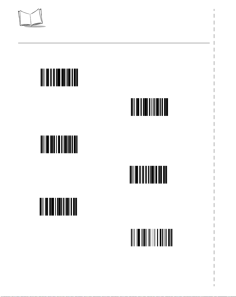
Commonly Used P470/P370 Programming Bar Code
Below are commonly used programming bar codes. You can cut this page out of the guide,
or make a copy of the bar codes using a high quality copying machine.
Enter System Menu Bar Code
Load New MCL-Designer Application
Scanner Firmware Version
Load 123Scan File
1-4
Cradle Firmware Version
Reset Default Applicat ion
(Clears previously programmed ADF rules and/or
MCL-Designer applications)
Page 21

Chapter 2
Set Up
Introduction
This chapter covers the procedures for setting up the RF scanner and its accessories.
Unpacking
Remove the scanner from its packing and inspect it for damage. If the scanner was
damaged in transit, call one of the telephone numbers listed in the section Symbol Support
Center on page xi. KEEP THE PACKING. It is the approved sh ippin g conta in er and should
be used if you ever need to return your equipment for servicing.
Setting Up the Cradle
The basic steps to set up the cradle are listed below and described in more detail in the
following sections.
• connecting the cradle to a host
• mounting the cradle, if desired
• pairing the scanner to the cradle.
Connecting to a Host
With some host types, the scanner is unable to answer host terminal polls if the appropriate
host type is not selected. This may result in an error message generated by the host. To
correct this situation, s elect the proper parameter se t and initialize the host terminal. See
Chapter 5, Parameter Menus for more information.
2-1
Page 22
P470/370 RF Scanner Product Reference Guide
There are two basic host communications options availa ble:
• using an RS-232 cable
• using a Synapse cable.
RS-232 Connection
1. Make sure all host devices are powered down.
2. Plug the connector at the end of the cradle’s cable into the appropriate RS-232
receiving port on the host device.
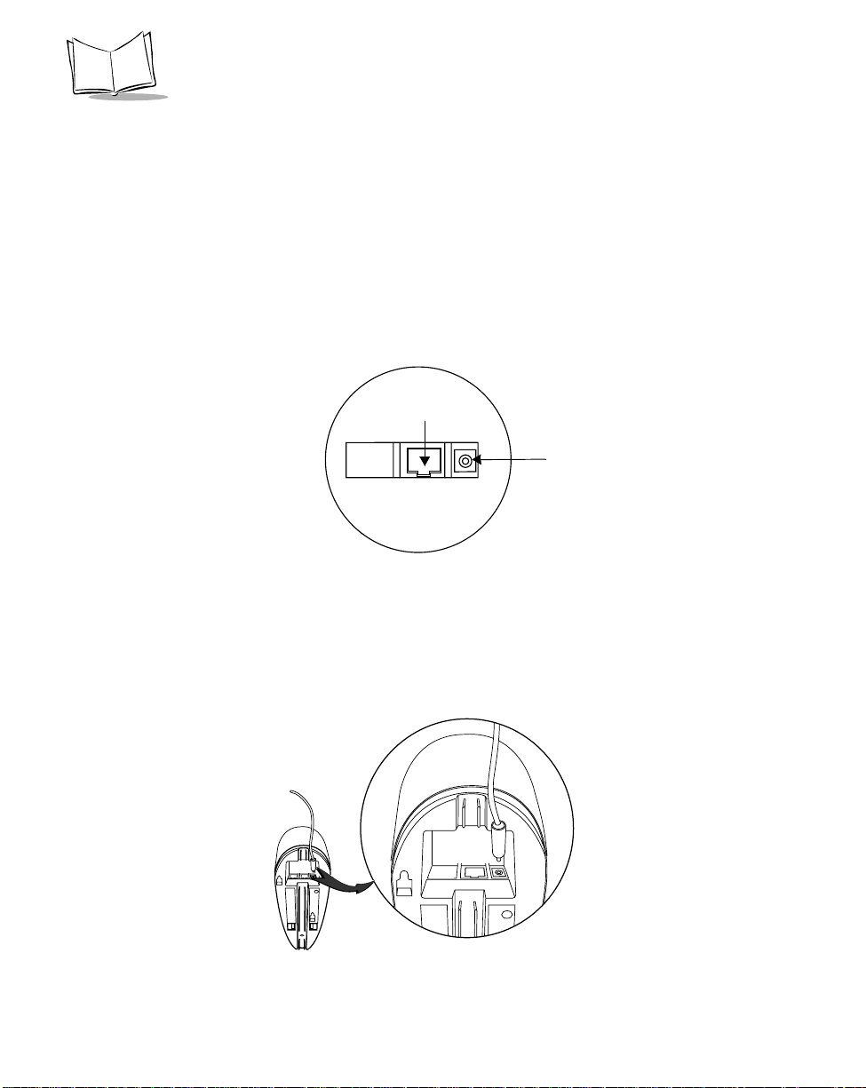
3. Plug the other end of the cable into the COM1 connector on the cradle.
COM1
Power port
Figure 2-1. Ports on the C rad le
4. Connect the power connector of the power supply i n to t he Power port on the
cradle.
5. Connect the appropriate line cord to the power supply and into an AC receptacle.
6. The indicator light on the cradle blinks, signifying successful power-up.
Figure 2-2. Power Supply Port
2-2
Page 23
7. Rotate the antenna to the vertical position.
Using A Synapse Cable
1. Make sure all host devices are powered down.
IMPORTANT
Before power is provided to the cradle (step 6), the following steps must be
completed. The Synapse cable must be connec ted to the cradle (step 2) AND
flying power lead plugged in (step 4). If the cables are not connected in this
sequence, the Synapse Interface Adapter will not operate properly.
2. Connect the Synapse cable to the cradle (see Figure 2-1 on page 2-2).
3. Connect the other end of the Synapse cable to the Synapse Interface adapter.
4. The Synapse cable has a flying power lead. Connect this lead to the receptacle in
the Synapse Interface adapter, as shown in Figure 2-3. See the Synapse guide for
details.
Set Up
the
To Host
Flyi n g Powe r
Lead
Synapse Interface
Adapter (Module)
Synapse
Cable
To Cradle
Figure 2-3. Synapse and Adapter Cable
5. Connect the Synapse Interface adapter to the host.
6. Connect the power supply to the cradle (see F igure 2-2 ).
2-3
Page 24
P470/370 RF Scanner Product Reference Guide
7. Connect the appropriate line cord to the power supply and into an AC receptacle.
8. The indicator light on the cradle blinks, signifying successful power-up.
9. Scan the appropriate Synapse bar codes to set up the Synapse cable for your
specifications.
10. Rotate the antenna to the vertical position.
Wand Emulation, OCIA, OCR, Keyboard Wedges
See the appropriate Synapse cable inst ructions. An adapter cable is required.
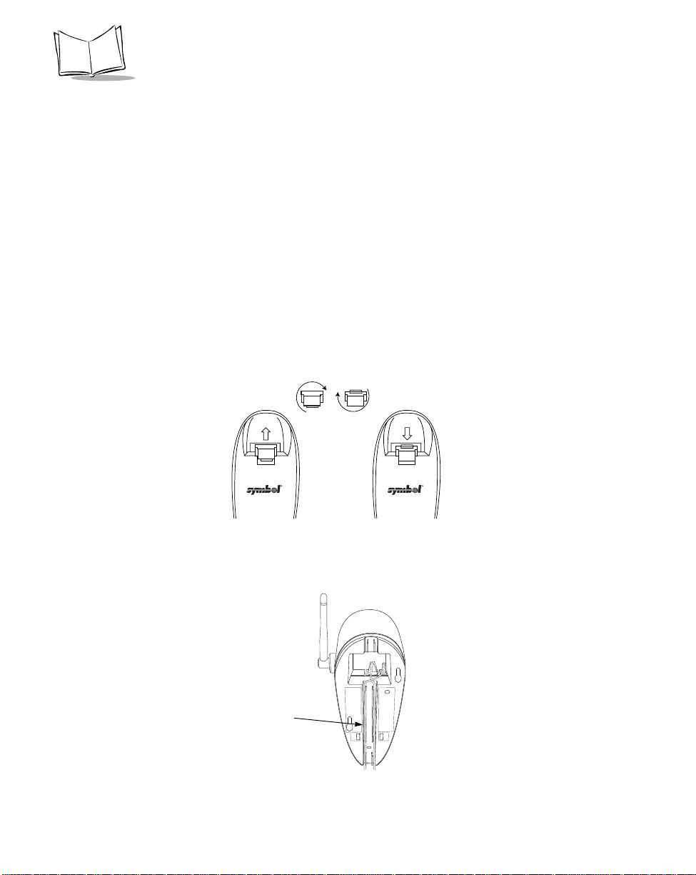
Wall Mounting
Before wall-mounting the cradle, the scanner support tab must be changed from the deskmount position to the wall-mount position.
1. Lift the scanner suppor t tab out of the top part of the cradle and replace it in the
wall-mount position.
Desk Mount
Wall Mount
Figure 2-4. Scanner Support Tab
2. Seat the cables from the bottom of the cradle in the grooves along the length of it
so that the bottom of the cradle is smooth.
Cable
Grooves
Figure 2-5. Placement of Cables
2-4
Page 25
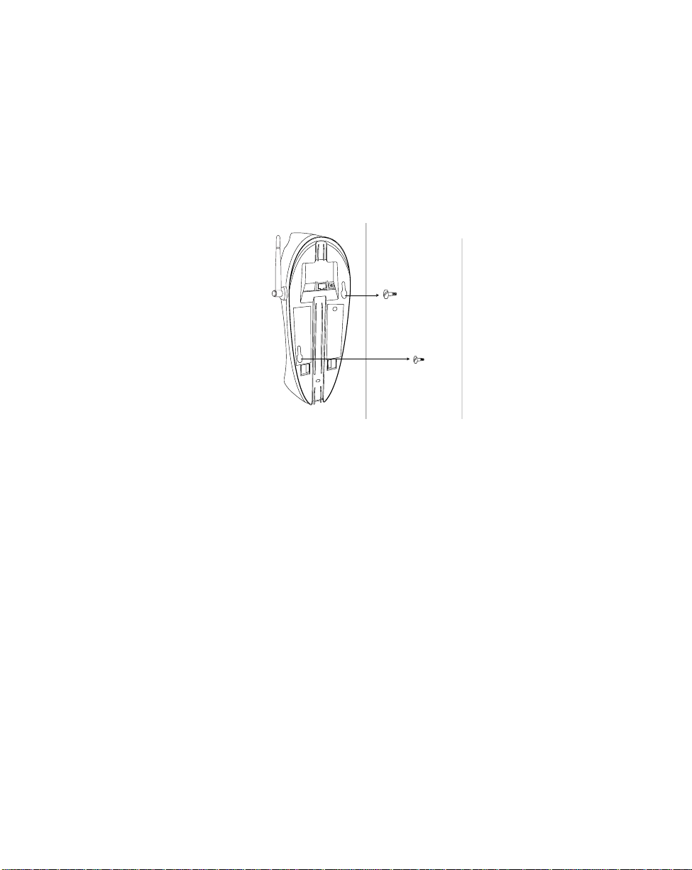
Set Up
3. Fasten the two screws provided into the wall where the cradle will hang, leaving
about 1/8” (0.3 cm) of the screw outside the wall for the cradle’s wall mounting
sockets (A template is provided for you in the PL 370/470 Quick Reference Guide
p/n 72-38494-xx).
4. Place the cradle over the screw heads and slide down until it fits into place. Slight
pressure upwards should not move the cradle.
Figure 2-6 . Securing Cradle to Wall
5. Position the antenna vertically (pointing toward the ceiling).
6. Place the scanner in the cradle.
2-5
Page 26

P470/370 RF Scanner Product Reference Guide
Pairing the Sc an ne r with the Cr ad le
The scanner and cradle must be paired for communication to occur.
If the cradle is attached to a new ho st, re-scan the pairing bar code.
Note:
To pair the scanner with the cradle:
1. Scan the pairing bar code on the top of the cradle.
To pair a long range scanner (P370 ALR) to a regular P370 cradle, attach the
“spare pairing b ar code” label to th e cradle. Thi s 15 mil bar code, packaged with
the cradle, can be scanned by the P370 ALR at a distance of approximately two
feet from the cradle.
2. The scanner may briefly display the “pairing search for channel” message while the
scanner searches for the base. Once the base is detected, information is
exchanged (addressing, RF channels, etc.) between the scanner and the cradle.
Note:It may take up to 30 seconds for the scanner to search for the base
during over-the-air pairing. To reduce the pairing time, place the
scanner in the cradle.
3. After the exchange is complete, the scanner and cradle are paired.
Successful pairing is indicated by a warble beep and the base’s LED will flash.
If pairing is unsuccessful, the scanner emits a Lo/Hi beep and displays the
following message:
Pairing Unsuccessful
Push ENTER & Try Again
The pairing of a scanner to a cradle is one-to-one. Only one scanner can be paired to a
cradle at any point in time. If you pair a second sca n ner to an in use cr adle, the cradle’s
connection to the first scanner will be broken and the connection re-established with the
second scanner.
To pair a scanner to a different cradle, scan its pairing bar code located on the top of the
cradle.
2-6
Page 27

Set Up
Optimizing RF Performance
Mounting
The RF scanner and cradle are equipped with a 2.4 GHz point-to-point radio that has an
RF transmission range of 100 feet (30.5 meters) even without a direct line of sight.
In addition to being a 2-way RF transmitter, the cradle is a battery charger and should be
mounted in an accessible location like on a table or desktop. For optimum RF performance,
especially in difficult environments, mount the cradle on a wall as high as possible.
Coexistence in Sp ec tr u m2 4 Environme nt s
If you operate your scanner or cradle in close proximity to a Spectrum24 device, maintain
a buffer of 3 feet or greater between the transmitters. A Spectrum24 device includes but is
not limited to a terminal with a Spectrum24 radio, PC with a Spectrum24 card, or a
Spectrum24 Access Point. If a scanner or cradle is less than 3 ft. from a 2.4 GHz
Spectrum24 transmitter (antenna), especial ly an Access Point, your communication
performance may degrade.
Select a Channel Outside the Spectrum24 band
In the unlikely event that Spectrum24 radio traffic causes interference between the scanner
and the cradle, you can change the s c anner’s RF channel to one that minimizes or
eliminates the interference.
Phaser cordless scanners have three channels that are not within the Spectrum24 band,
81, 82, and 83*. As a rule of thumb, the Cordless systems operated closest to Spectrum24
devices should use these channels. For instructions on how to change the scanner’s RF
channel, see System Setup Options on page 3-8.
In applications with low scanning/data transmission duty cycles, you may assign the same
channel to more than one cordless scanner.
After channels 81, 82 and 83, the next best channels to use are 60 through 80; t he higher
the channel the better. See Appendix C, Radio Channels for a list of available radio
channels per country.
* Not available in some countries.
2-7
Page 28

P470/370 RF Scanner Product Reference Guide
Phaser-to-Phaser Co-Existence
Up to three P470/370 scanners within listening range (100 feet) of each other can be
operated on the same channel with little or no interference, assuming average scanning
rates.
For higher than average scanning rates, P470/370 scanners wi thin listening range (100
feet) of each other should be operated on different channels, set apart by at leas t one
channel (for example, 2, 4, 6, etc.). Cordless Phaser scanners support up to 82
communication channels. Not all channels are available in all countries. Refer to Appendix
C, Radio Channels for more information.
Increase the nu mb er of RF Retries
If the scanner’s tr ansmission is not received by the cradle or the base’s acknowledgment
response is not received by the scanner (see Communication Errors on page 3-5), the
scanner retransmits the lost or corrupted data. The scanner attempts 4 RF Retries (default)
but can be programmed to attempt up to 8.
Depending on your particular RF environment, additional retries may cause you r scanner
transaction time to increase in the presence of heavy S pectrum24 traffic.
Charging the Battery
Before its first use, the scanner’s battery must be charged. It can be charged:
• Using the cradle
• Using the UBC 2000.
2-8
Page 29
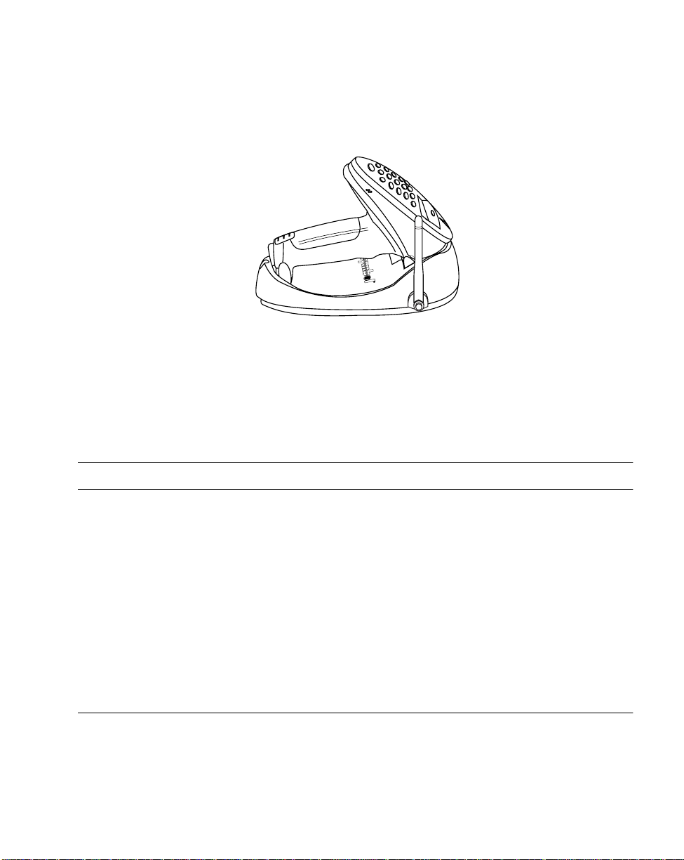
Using the Cradle
1. Set up the cradle as described in Setting Up the Cradle on page 2-1. .
Figure 2-7. Placing the Scanner into the Cradle
2. Insert the scanner into the cradle so that the nose of the scanner and tip of the
handle seat into the receptac les. The scanner displays “UNIT CRADLED” when
properly inserted in the cradle.
3. The battery charges automatically. A full charge of a depleted battery takes
approximately 3-1/2 hours.
Set Up
For additional information on charging, see Table 4-1 on page 4-3.
Note:
The cradle recharges batteries in the scanner only when the scanner is in the cradle. A
scanner with a depleted battery starts charging immediately upon insertion into the cradle,
whereas a scanner with a partially charged battery begins charging after approximately 15
minutes. Note that the scanner can be removed from the cradle at any time.
Using the UBC 2000
The battery can be charged using the Universal Battery Charger UBC 2000. The UBC
adapter for the P470/P370 scanner battery is required. Refer to the UBC 2000 guide for
information on recharging the battery using the UBC 2000.
Battery Charge
When the battery’s charge is almost depleted, the scanner emits 4 high tone beeps, when
the trigger is pulled, indicating that it must be recharged.
2-9
Page 30

P470/370 RF Scanner Product Reference Guide
2-10
Page 31

Chapter 3 Operation
Introduction
This chapter covers how to use the cordless Phaser scanner.
Default Applica t ion
The cordless scanner is shipped from the factory with a default scan and transmit
application.
This application allows users to scan and view data, enter quantities, and manually enter
alphanumeric data.
When the unit is powered u p, it displays the system start-up banner. Alte rnative ly, t he
scanner can be reset manually by pressing the <FUNC> key, then the <*> key. When the
scanner is power ed up or reset, the system banner appears as fo llows :
Symbol Technologies
Phaser RF
3-1
Page 32

P470/370 RF Scanner Product Reference Guide
Initial Powerup
After a few second s, the System Ba nner is replaced by the system initializat ion screen.
Symbol Technologies
Initializing...
After initialization, the scanner enters the Scan & Transmit application. The default
communication pro tocol is RS232/ Synapse.
If a Synapse cable is attached, the scanner automatically overrides the default se ttin g s.
Scan and Trans m it App lic ation
The scan and transmit application allows you to:
• Display and simultaneously transmit data to a host
• Eliminate repetitive scanning with a quantity entry feature
• Manually enter alphanumeric data if no bar code is present.
If the scanner powers down, pull the trigger or press the <ENTER> key to wake it up.
The scan and transmit screen appears as follows:
SKU:
_____________________
In this mode, scanned bar codes are automatically transmitted to the cradle and then the
host in real time.
Numeric Data Entry
The default application also allows you to manually enter data if no bar code is present.
By default, this feature is enabled. To disable alphanumeric data entry via the keypad, go
to the symbologies tab inside 123Scan and remove the “X” from the check box next to
“Keypad”. (This does not disable the quantity entry feature discussed in Eliminating
Repetitive Scanning on page 3-4.)
3-2
Page 33

Operation
With keypad entry enabled (default setting out of the box), press the <ENTER> key a ft er
keying in data. During data entry , the <BK> key corrects keying errors digit by digit, and the
<FUNC> then <BK> combination clears the screen so you can start over. If your entry
exceeds 34 characters, the characters will scroll off the visible portion of the screen, but are
retained for storage.
Alpha Data Entry
To enter alpha characters via the key pa d (with keypad enabled, page 3-26), press the
<Mode> key once to put the sc anner in Alpha Mode.
Numeric buttons 1 through 9 are as sociated with the alpha characters. For example, the
letters A, B and C are located on numeric button 7. Press the button with the letter you
desire - once for the letter A, twice for the letter B, or three times for the le tter C. You can
continue entering alpha characters or switch to numerics. Press <ENTER> to send the
data.
To ret urn to numeric entry mode after entering alpha characters, press the <Mode> key
again. For example, to manually enter 17ABF5, do the following steps :
Data Action
1 Press numeric button 1.
7 Press numeric button 7.
A Press <MODE> button once, then numeric
button 7 once. Wait for one second (you will hear a
low pitched beep).
B Press numeric button 7 twice.
F Press numeric button 8 three times.
5 Press <MODE> button once, then numeric
button 5 once, then < ENTER>.
For more information, refer to Keypad Operation on page 3-26.
3-3
Page 34

P470/370 RF Scanner Product Reference Guide
Eliminating Re pe tit ive Scanning
T o eliminate repetitive scanning of identical items, you can enter a quantity prior to scanning
a bar code. This quantity entry feature can also be used when manually entering bar code
data.
To enter a quantity, press the * key. The following screen with a defaul t value of “1” will
appear:
Quantity:
_____________
1
^
To enter the value you desire, key in the quantity followed by the <ENTER> key. Next, the
bar code data entry screen reappea rs. Scan t he item’s bar c ode. The scanner sends t he
bar code data to the host the keyed-in amount of times. For instance, if you type in a
quantity of 6 then sca n a bar code, the scanner sends that bar code data to the host six
times as if the bar code had been scanned six times.
If you have accidentally entered this screen, it will automatically be exited after 5 seconds
or by pressing the <ENTER> key without entering a quantity.
3-4
Page 35

Operation
Communication Errors
A communication error occurs w hen the scanner, cradle or host fails to pr operly
communicate. When a communication error occurs using the default application, the
scanner emits 4 bee ps (LO HI LO HI) and displays a "Failed Communication" error
message, like the one shown below. The three-digit error code on the scanner screen
indicates what type of communication problem occurred. Error code 015 generally
indicates the scanner is out of RF range, not properly p aired to the base, or the base may
have lost power. For a detailed list of all the error codes see Appendix D, Messages and
Error Codes and Beeper Ind ications / Default Application Error Codes on page 4-7.
Failed Communication
Error 015 Push ENTER
To ret urn to the application, press <ENTER>.
Three types of communication errors can occur:
1. The RF transmitted data was NOT received by the cradle.
2. The cradle received the RF transmitted data, but the scanner did NOT receive a
cradle's acknowledgment.
3. The host and cradle are not communicating properly.
RF Communication Errors
1. If the RF transmitted da t a was NOT received by the cradle, move the scanner
closer to the cradle to reestablish communication, then re-scan the bar c ode. If the
communication has been reestablished, the scanner will sound a good decode
beep and no error beeps. Resume normal scanning.
2. If the cradle received the RF transmitted data, but the scanner did NOT receive a
cradle's acknowledgment, move the scanner closer to the cradle to reestablish
communication, then re-scan the bar code. If the communication has been
reestablished, the scanner will sound a good decode beep and no error beeps. In
this scenario data may have been transmitted to the host. If the cradle had
previously sent data to the host, it will NOT pass this re-scanned data to the host.
Resume normal scanning.
For additional information see Optimizing RF Performance on page 2-7.
3-5
Page 36

P470/370 RF Scanner Product Reference Guide
Host / Cradle Communicat ion Errors
3. If the host and cradle are not communicating properly , insure the cabling is properly
connected, baud rate is properly se t, and correct COM port has been selected.
3-6
Page 37

Operation
System Menu
The system menu allows the user to set up the operation of the scanner, such as loading a
new application, set the scanner’s RF channel, setting the scanner ID, etc.
Enter the System Menu by scanning the bar code below or by entering a keypad sequence.
Commonly used System Menu programming bar codes have been consolidated on
page 1-4.
Enter System Menu Bar Code
To access the System Menu using the keypad sequence, press the <FUNC>, then the <*>
key, followed by the <FUNC> key, then the <BK> key.
When you enter the system menu, the following screen appears:
Phaser Setup
0. System Setup
Below is the list of available options. Press the Up and Down arrow keys to scroll
through them. Press <ENTER> to select a menu option. You can also select a menu option
directly by typing the associated menu option number and then pressing <ENTER>.
0. System Setup
1. App. Control
2. Parameter Control
3. System Status
4. Version
9. Return to App.
The system menu options are described below.
3-7
Page 38

P470/370 RF Scanner Product Reference Guide
System Setup Opt ion s
System Setup allows you to configure the scanner ’ s ba s i c se t t i n gs such as set t i n g an RF
channel.
Option Description
0. Set Com Protocol
-RS232/Synapse
-MCL NET
-Back to Com Protocol
1. Set RF Channel Allows the user to set/change the RF channel used for
Sets the commu nication pro tocol used by the defau lt applicat ion.
The options ar e MCL-Net or RS232/Synapse. If RS232/Syn apse
is selected, the scanner automatically identifies whether an RS232 or Synapse interface is required. To cancel the change,
press the <FUNC> then <BK> keys, and to accept the change,
press the <ENTER> key.
communication between the scanner and cradle.
The cordless Phaser scanner operates on a single,
programmable channel (frequency) between 2.402 GHz
(channel 02) and 2.483 GHz (channel 83).
A maximum of 81 channels are available. Not all channels are
available in all countries. If a channel is not legal to use in your
country, an error beep will be heard instead of a successful
warble. For a list of Channel Availability by Country, see
Appendix C, Radio Channels.
Channel: 54
New Channel: _ _
To cancel the change, press the <FUNC> then <BK> keys, and
to accept the change, press the <ENTER> key .
2. Set Contrast Sets the display contrast. The scanner displays the current
contrast setting. Use the up and down arrow keys to change the
contrast. Th e default contrast is 7, and the ran ge is from 0 to 15,
with 0 being the lightest and 15 being the darkest. To cancel the
change, press the <FUNC> then <BK> keys, and to accept the
change, press the <ENTER> key.
3. Set Scanner ID Sets the scanner ID. The sca nner displays it s current ID, and t he
user may key in a new value between 1 and 254. The default is
001. To cancel the change, press the <FUNC> then <BK> keys,
and to accept the change, press the <ENTER> key.
9. Back to Main Returns the user to the system menu.
3-8
Page 39

Operation
App. Control
App. Control allows you to control your application, specifically, load new applications on
your scanner, reset your default applications, etc.
Y ou can load a new application or system code by either scanning the appropriate bar code
or entering the appropriate keypad value as indicated on the display.
Option Description
0. Load App Put s the scanner into a mode to receive MCL-Designer
application downloads and MCL-Link commands from the host.
To ente r this mode using the key pad, select this option on the
system menu. The following screen displays:
Load New App.
<BK>=NO
<ENTER>=YES
OR
To ente r this mode from an application without entering the
system menu or entering key strokes, scan the bar code below.
Load New MCL-Designer Application
Scanner ready,
on PC start download
When th is screen displays, th e scanner is ready to accept th e
download. On the PC Utility, initiate the download.
After downloading is complete, the system menu is exited and
the application initiated.
T o exit thi s mode and prevent the download of a new application,
press the <FUNC> then <BK> keys.
3-9
Page 40

P470/370 RF Scanner Product Reference Guide
Option Description
1. Set Defa u lt A p p Reinstalls the default application and returns all parameters to
their factory settings (values listed in Table 5-1). The default
application over writes any MCL-Des igner applicat ion and/or ADF
rules. This option may be used to restore functionality to a
scanner which has been loaded with a defective application.
To ente r this mode using the key pad, select this option on the
system menu. Prior to resetting the default app lica ti on, the user
is prompted to confirm this operation:
Reset Default App?
<BK>=NO
<ENTER>=YES
Press the <ENTER> k ey to c onf irm t he choi ce (Yes) or the <BK>
key to cancel the choice (No).
If you entered “Set Default App” from the System Menu, upon
resetting the default application, you will return to the System
Menu.
OR
To ente r this mode from an application without entering the
system menu or entering key strokes, scan the bar code below.
3-10
Reset Default Application
(Clears previously programmed ADF rules and/or
MCL-Designer applications)
If you entered the “Set Default App” mode using the bar code
above, the default application will automatically be reset, the
System Menu exited, and the application re-initiated.
Page 41

Option Description
Operation
2. Enable AutoLoad
AutoLoad App.
-Enable
-Disable
Enables the automatic application download feature in the
default application. This allows the user to remove the scanner
from the box , pair it with the cradle, pl ace the scanner in the
cradle and automatically download a new application to the
scanner.
In order f or this feature to operate properly, the cradle must be
connected to a host r unning MCL-Link, and the use r’s host must
be configured properly with specific files in specific locations
(See Appendix A). If the user does not set up the host in the
required manner, the scanner reverts to normal charging mode.
This feature is enabled by default , but may be di sabled b y use of
this System Menu item.
Selecting Enable will enable this feature; Disable will disable
this feature. To exit without changing thi s se tting, press <FUNC>
then <BK>.
Note that “Enable AutoLoad” ONLY works with the default
application and does not work with any MCL Designer generated
applications.
3-11
Page 42

P470/370 RF Scanner Product Reference Guide
Option Description
3. System Code Updates the scanner opera ting syst em (Firmwar e). To enter this
mode using the key pad, select this option on the system menu.
Load New System Code
<BK>=NO
<ENTER>=YES
Press the <ENTER> k ey to c onf irm t he choi ce (Yes) or the <BK>
key to cancel the choice (No).
OR
To ente r this mode from an application without entering the
system menu or entering key strokes, scan the bar code below.
System Code
3-12
Place unit in cradle
on PC start download
Place the scanner in the cradle before initiating the download
from the PC Utility.
After the download is c o mp lete, the sy s t em me n u is exited and
the application initiates.
To exit this mode and prevent the download of new firmware,
press and hold the <ENTER> key for 30 seconds. In addition,
power to the cradle must be cycle d (powered off then on) befor e
it will com m u nicate with the s canner a gain.
Page 43

Operation
Option Description
4. Base Station Code Updates the cradle’s operating system (Firmware). To enter this
mode using the key pad, select this option on the system menu.
Load New Base Code
<BK>=NO
<ENTER>=YES
Press the <ENTER> k ey to c onf irm t he choi ce (Yes) or the <BK>
key to cancel the choice (No).
OR
To ente r this mode from an application without entering the
system menu or entering key strokes, scan the bar code below.
Base Station Code
Base Station ready,
on PC start download
To start the download to the cradle, press the start button on the
PC Utility.
Note: You will automatically exit this message after 15 seconds
and return to the application, even if the PC download is NOT
initiated.
To exit this mode and prevent the download of new firmware or if
the PC download is not initiated, the power to the cradle must be
cycled (powered off then on) before it will communicate with the
sca nner again. No action i s required on the scanner side.
9. Back to Main Returns the user to the system menu.
3-13
Page 44

P470/370 RF Scanner Product Reference Guide
Parameter Control
Parameter Control allows you to control the scanner parameters such as Scan Parameters
and Set Default Params.
Option Description
0. Scan Parameters This f ea ture only works when used with an application generated
with MCL-Designer and allows you to program your scanner by
scanning the bar codes in Chapter 5, Parameter Menus.
Parameters already set in your MCL-Designer generated
application can not be overridden by scanning bar codes.
When you see the following screen, you can begin scanning
parameter bar codes:
Scan Parameters
<FUNC> <BK> to quit
After scanning t he desired bar cod es, press < FUNC> then <BK> to
exit this mode.
1. Set Default Param Restores the default parameters in the scanner. The default
parameters overwrite any scanned parameters. Prior to resetting
the default parameters, you are prompted to confirm your choice.
9. Back to Main Retur ns the user t o the syst e m men u.
System Status
Syst e m Statu s allow s you to perform syste m c h ecks such as Battery Check.
Option Description
0. Battery Check Checks the battery charge level.
Good indicates the battery does not require recharging.
Low/Recharge indicates the scanner requires a recharge.
When the battery is close to complete discharge, the following
message displays:
Recharge Battery
9. Back to Main Retur ns the user t o the syst e m men u.
3-14
Page 45

Operation
Version
0. Scanner Version This option displ ays the version of firmware (oper ating syst em) run
by the scanner. For example, the firmware version shown on the
display below is NBR VRAAG, also called Revis ion “G” (which is th e
last letter of the firmware’s full name NBRVRAAG).
To enter this mode using the keypad, select this option on the
Sys tem Men u. The fol lowing screen dis plays .
Scanner: NBRVRAAG
MCL: 4.1
If you entered “Scanner Version” from the System Menu, after 15
seconds or by pressing <ENTER>, you will return to the System
Menu.
OR
T o enter this m ode from an applicat ion outside of the Syst em Menu,
scan the bar code below.
Scanner Firmware Version
If you entered “Scanner Version” using the bar code above, after
15 seconds or by pressing <ENTER>, you will automatically exit
the S y stem M enu and re-enter the app lication.
3-15
Page 46

P470/370 RF Scanner Product Reference Guide
1. Cradle Version This option displ ays the version of firmware (oper ating syst em) run
by the cordless scanner’s cradle. For example, the f ir mware
version shown on the display below is NBRVCAAF, also called
Revision “F” (which is the last letter of the firmware’s full name
NBRVCAAF).
To enter this mode using the keypad, select this option on the
Sys tem Men u. The fol lowing screen dis plays .
Cradle: NBRVCAAF
If you e n t ered “Cradle Version” from the System Menu, after 15
seconds or by pressing <ENTER>, you will return to the System
Menu.
OR
T o enter this m ode from an applicat ion outside of the Syst em Menu,
scan the bar code below.
Cradle Firmware Version
If you en t ered “C radle Version” using the bar code above, after 15
seconds or by pressing <ENTER>, you will automatically exit the
System Menu and re-enter the application.
9. Back to Main Retur ns the user t o the syst e m men u.
Return to App
Return to App. Return to App exits the system menu and ret urns to the application.
To d o this, press <9> then <ENTER>.
3-16
Page 47

Operation
123Scan
123Scan is an intuitive Windows based utility that allows you to customize your scanner
setup and generate Advanced Data Formatting (ADF) rules. An Advanced Data Formatting
rule gives you the abili t y to modify the bar code data before sending it to the host such as
appending a carriage return, or some other prefix/suffix value, to the bar code data. This
enhances capability between bar code data and your host software, allowing you to
program the scanner rather than modifying your host application. The cordless scanner can
be programmed via a cordles s ( RF) download or by scanning 123Scan generated
programming bar codes. Scanner programming is saved in a setup file which can be
distributed electronically (Web site, floppy disk, E-mail, or fax).
A copy of 123Scan is on the CD included with your scanner. It is also available on the
Symbol Web site http://www.symbol.com. Use the web site’s search tool to find
“123Scan” and selec t the P470/370 product line.
Note:Advanced data formatting rules created with 123Scan are for use
with the default application only and will not work with applications
created with MCL-Designer.
To download a 123Scan generated ADF rule, scan the bar code below, then initiate the
download on the PC u tility.
Load 123Scan File
To remove p reviously progra mmed ADF rules from the scanner, scan the bar code below.
Reset Default Application
(Clears previously programmed ADF rules)
3-17
Page 48

P470/370 RF Scanner Product Reference Guide
Suffix Values
123Scan generated programming bar codes for two commonly used suffixes (Enter and
Tab) have been included in this Produ ct Reference Guide.
To append an Ent er key
codes and then the Reset Scanner bar code, in that order.
ASCII value 7013
*
to the transmitted bar code data, scan all nine (9) ADF rule bar
*
ADF Rules
1/9
2/9
3/9
3-18
4/9
Page 49

5/9
6/9
7/9
Operation
8/9
9/9
RESET SCANNER
3-19
Page 50

P470/370 RF Scanner Product Reference Guide
To append a Tab* to the transmitted bar code data, scan all nine (9) ADF rule bar c odes
and then the Reset Scanner bar code, in that order.
ASCII value 7009
*
ADF Rules
1/9
2/9
3-20
3/9
4/9
Page 51

5/9
6/9
7/9
Operation
8/9
9/9
RESET SCANNER
3-21
Page 52

P470/370 RF Scanner Product Reference Guide
Scanning
The scanner ships with the defau lt appl i c at ion and default parameters and is ready-to-use
right out of the box. If this is not what you need for your application, refer to the MCL
Designer Manual for programming instructions and Chapter 5, Parameter M enus for
scanning and communications parameters. If you need assistance, contact your local
supplier or Symbol Support Center.
1. Make sure the bar code is in the correct scanning range. Aim and press the trigger.
The scanner has read the symbol wh en:
• You hear a beep.
• The LED above the screen turns green.
• The red laser turns off.
Figure 3-1. Scanning a Bar Code
Scan the Entire Symbol
• Your scan beam must cross every bar and space on the symbol.
• The larger the symbol, the farther away you should hold the scanner.
• Hold the scanner closer for symbols with bars that are close together.
• A short, high tone beep indicates a good decode.
3-22
Page 53

Operation
Right Wrong
Hold at an Angle
Do not hold the scanner directly over the bar code. Laser light reflecting directly back into
the scanner from the bar code is known as specular reflection. This strong light can “blind”
the scanner and make decoding difficult. The area where specular reflection occurs is
known as a “dead zone.”
You can tilt the scanner up to 65° forward or back and still achieve a successful decode.
Simple practice quickly shows what tolerances to work within.
65
65
Shaded area represents
+
dead zone ( 2 )
_
Scan
Beam
Bar Code Bar Code
Figure 3-2. Maximum Tilt Angles and Dead Zone
Bar Code
Scan
Beam
3-23
Page 54

P470/370 RF Scanner Product Reference Guide
Decode Zone
5 mil
7.5 mil
10 mil
100% UPC
15.6 in.
39.6 cm
10 in.
25.4 cm
5 in.
12.7 cm
0 in.
0 cm
5 in.
12.7 cm
10 in.
25.4 cm
15.6 in.
39.6 cm
Width
Of
Field
3-24
0 in.
0 cm
15 mil
20 mil
40 mil
55 mil
5 in.
12.7 cm
10 in.
25.4 cm
15 in.
38.1 cm
20 in.
50.8 cm
25 in.
63.5 cm
30 in.
76.2 cm
35 in.
88.9 cm
40 in.
101.6 cm
Distance From Front Of Scanner
Figure 3-3. P470/P370 1D Scanner - Decode Zone
45 in.
114.3 cm
Page 55

0 in.
0 cm
100% UPC
15 Mil
35 in.
88.9 cm
40 Mil
55 Mil
70 in.
177.8 cm
105 in.
266.7 cm
70 Mil Reflective
100 Mil Reflective
140 in.
175 in.
444.5 cm
210 in.
533.4 cm
355.6 cm
Distance From Front Of Scanner
245 in.
622.3 cm
280 in.
711.2 cm
315 in.
800.1 cm
350 in.
889.0 cm
Operation
20.0 in.
50.4 cm
15.0 in.
38.1 cm
10 in.
25.4 cm
5 in.
12.7 cm
0 in.
0 cm
5 in.
12.7 cm
10 in.
25.4 cm
15.0 in.
38.1 cm
20.0 in.
50.8 cm
385 in.
977.9 cm
Width
Of
Field
Figure 3-4. P370 ALR Scanner - Decode Zone
3-25
Page 56

P470/370 RF Scanner Product Reference Guide
Keypad Operation
Instead of scanning a bar code, you can enter the bar code data using the keypad on the
top of the scanner. By de f ault, this feat u re is ena b led. To disable alphanumeric da ta entry
via the keypad, go to the symbologies tab inside 123Scan and remove the “X” from the
check box next to “Keypad”. (This does not disable the quantity entry feature discussed in
Eliminating Repetitive Scanning on page 3-4.)
For additional information on 123Scan, see 123Scan on page 3-17.
To enter numeric data, type the numeric value desired and press <ENTER>. A beep lets
you know that the entry was accepted. S ee Figure 3-5 on page 3-27.
To enter alpha characters, press the <Mode> key once to put the scan ner in Alpha Mode.
Numeric buttons 1 through 9 are as sociated with the alpha characters. For example, the
letters A, B and C are located on numeric button 7. Press the button with the letter you
desire - once for the letter A, twice for the letter B, or three times for the le tter C. You can
continue entering alpha characters or switch to numerics. Press <ENTER> to save or send
the data.
To ret urn to numeric entry mode after entering alpha characters, press the <Mode> key
again. For example, to manually enter 17ABF5, do the following steps :
Data Action
1 Press numeric button 1.
7 Press numeric button 7.
A Press <MODE> button once, then numeric
button 7 once. Wait for one second (you will hear a
low pitched beep).
B Press numeric button 7 twice.
F Press numeric button 8 three times.
5 Press <MODE> button once, then numeric
button 5 once, then < ENTER>.
Every time you press the butt on with the letter you desire, you hear a low-pitched beep to
let you know that the entry was registered. Although the entry is registered, it has not been
3-26
Page 57

Operation
transferred to the host yet. A high-pitched beep lets you know that the entry has been
transferred to the host.
To ret urn to numeric mode, press the Mode key again. Pressing the Enter key saves the
data.
To put a decimal point (.) into numeric data, type in the numbers before the decimal point,
then press the mode key, press the decimal, and press the mode key again. Now r e s u m e
typing in the values to the right of the decimal.
To enter a dash (-), press the mode key once, then the zero (0) key twice.
To enter a blank space ( ), press the mode key once, then the zero (0) key three times.
The Function key in combination with a num er ic key can be programmed to launch an
operation. For more information on how to program these keys for additional tasks and
operations, refer to the MCL Designer User’s Guide p/n 70-37689-XX.
Figure 3-5. Scanner Keypad
3-27
Page 58

P470/370 RF Scanner Product Reference Guide
Troubleshooting
Refer to Appendix D, Messages and Error Codes for additional troubleshooting information.
Table 3-1. Troubleshooting Table
Problem Solution
General problem solving
The scanner emits error
beeps after decoding a
bar c ode.
• Check that the power supply is attached to the cradle.
• Check for loose cable connections at the cradle, AC power
supply , or host device.
• Make sure the scanner and c r adle have been successfully
paired.
• Check the sca nner’s battery charge level. See Battery
Check on page 3-14.
• Make sure the device is programmed to read the type of bar
code you want to scan.
• Check t he symbol to make sure it is not defaced.
• Try scanning another similar symbol of the same code type.
• Be sure you’re within the proper scanning decode range.
• Make sure you are within the proper RF transmission
range.
• Cycle power (power off then on) to the base.
• Reboot (reset) the sc anner (hold down the ENTER key for
about 30 seconds) and try scanning again.
• Check t hat th e cr adle is powered up and that it’s cable
connections are secure. See Setting Up the Cradle on page
2-1.
• Check that the scanner is successfully paired with the
cradle. See Pairing the Scanner with the Cradle on page 2-
6.
• Check that you are within transmitting range. See
Communication Errors on page 3-5 and Appendix D,
Messages and Error Codes.
3-28
Page 59

Table 3-1. Troubleshoo ting Table ( Continued)
Problem Solution
Operation
The scanner does not
scan the programming
bar codes in this PRG.
The PC cannot downl oad
an application to the
scanner.
Received an 015
communication error
while using a Synapse
cable.
The P370 ALR scanner
will not pair with a PL370
cradle.
• For MCL-Designer generated applications, put the scanner
into “Scan Paramet er” mode in the system menu (see Scan
Parameters on page 3-14).
• For the default application running on a previous version of
firmware (Revision F or lower, such as E), put the scanner
into “Scan Paramet er” mode in the system menu (see Scan
Parameters on page 3-14). For instructions on how to
check the scanner’s firmware version, see Version on page
3-15.
• Check to make sure you are using an RS-232 cable. The
application can not be downloaded to a scanner using a
Synapse cable.
• Make sure the scanner and cradle are successfully paired.
• Check to make sure the power supply is conne cted t o the
base.
• If the problem continu es, cycle power to the base (powered
off then on).
• The cables connected to the cradle were not connected in
the correct sequence. Before power is applied to the cradle,
the Synapse cable must be connected to the c r adle AND
the flying power lead plugged in. See Using A Synapse
Cable on page 2-3 for more information
• To p air a long range P370 ALR scanner with a PL370
cradle, attach the spare pairing bar code label to the cradle
and scan the b ar c ode. For additional information, see
Pairing the Scanner with the Cradle on page 2-6.
3-29
Page 60

P470/370 RF Scanner Product Reference Guide
Table 3-1. Troubleshoo ting Table ( Continued)
Problem Solution
The Scanner wil l not load
my ADF rule.
• Software downlo ad to the scanner while the scanner is
running the default application.
• Check that the scanner is successfully paired with the
cradle (see page 2-6).
• Check that the cradle and PC are connected using an
RS-232 cable.
• Software download or scanning a bar code sheet while the
scanner is running an MCL-Designer generated application
• Erase the MCL-Designer application from the
scanner’s mem ory by scanning the “Reset Default
Application” bar code on page 3-10.
• The default application is now reinstalled and an ADF
rule can be loaded.
Note:If after performing these checks the symbol still does not scan,
contact your distributor or call the Symbol Support Center. See
Symbol Support Center on page page xi for the telephone number.
3-30
Page 61

Chapter 4
Maintenance And Specifications
Introduction
This chapter explains how to maintain your scanner and t he s pec ifications f or it.
Maintenance
• Do not allow any abrasive material to touch the scanner window.
• Remove any dirt particles with a damp cloth.
• Wipe the scanner window using a damp cloth, and if necessary, a non-ammonia
based detergent.
• Do not spray water or other cleaning liquids directly into the scanner window.
• If the contacts between the scanner and cradle become dirty, clean them with
either a pencil eraser or a cotton swab dampened with alcohol.
• If a significant decrease in battery life is noticed and does not correspond to
increased usage, consider replacing the battery.
Changing the Battery
Once a battery is fully charged, it w ill generally last up to 10 hours without being returned
to the cradle. By returning it to the cradle during the day, you extend this time.
4-1
Page 62

P470/370 RF Scanner Product Reference Guide
Removing the Batter y
1. Slide the release latch down using center indent and remove the cover.
Battery
Compartment
Cover
Figure 4-1. Removing the Battery Compartment Cover
2. Slide the battery toward the bottom of the scanner and then pull the bottom of the
battery back and out of the scanner.
Battery
Release
Latch
Figure 4-2. Pulling the Battery Out
Replacing the Battery
1. Place the top portion of the battery (curved side up, contacts toward top) into the
scanner and then slide it up the handle.
2. Replace the battery compartment cover.
3. Slide the release latch up to secure the cover in place.
4-2
Page 63

Maintenance And Specifications
Charge Status LED Indications
The LED indicator on the cradle uses flashing patterns to display the charger status, as
shown in the table below.
Table 4-1. Cradle LED Indications
LED Status
Off The scanner is not in the cradle or has not been
properly inserted into the cradle.
Blinking Slowly The scanner is properly seated in the cradle and
charging will begin shortly.
Blinking Rapidly The battery is actively charging.
On B a ttery charging is complete.
4-3
Page 64

P470/370 RF Scanner Product Reference Guide
Technical Specifications
Table 4-2. Technical Specification s
Item Description
Decode Capability The RF scanner can be programmed to decode the following
code types: UPC/EAN, Bookland EAN, Code 11, Code 39,
Co d e 3 9 F u l l ASC II, Triop t i c Code 39, C ode 93, C odabar,
Interleaved 2 of 5, Code 128, EAN 128, Discrete 2 of 5, MSI
Plessey, and Coupon Code.
The RF scanner can au to- discr iminat e betwee n al l of the above
code types except for Code 39 and Code 39 Full ASCII.
Scanner Beeper Operation User-selectable: Enabled, Disabled.
Scan R epetition Rate 35 (± 5) scans/sec (bidirectional)
Roll (Skew) Tolerance ± 30° from normal
Pitch ± 65° from normal
Yaw ± 60° from normal
Decode Depth of Field See Decode Zone on page 3-24.
Print Contrast Minimum 20% absolute dark/ light diff erential, measur ed at the wavele ngth
of the laser diode.
Ambient Light Immunity
Artificial Lighting 450 ft. candles 4844 lux
Sunlight 10,000 ft. candles 107,640 lux
Operating Temperature
P370 (Industrial)
P470 (Retail)
Storage Temperature -40° to 140°F-40° to 60°C
Sealing P370: All components sealed to IP 54 specification against
Humidity 5% to 95% (non-condensing)
Durability (Scanner)
P370 (Industrial)
P470 (Retail)
-4° to 122°F-20° to 50°C
32° to 104°F0° to 40°C
wind blown dust and rain.
P370: 6-ft. (1.8 m)
P470: 5-ft. (1.5 m)
Drops to concrete over entire temperature range
4-4
Page 65

Maintenance And Specifications
Table 4-2. Technical Specifications (Continued)
Item Description
Dimensions
Height 7.0 in. (17.8 cm)
Width 9.2 in. (13.5 cm)
Depth 3.5 in. (9.8 cm )
Laser Classifications CDRH Class II, IEC Class 1, IEC Class 2
4-5
Page 66

P470/370 RF Scanner Product Reference Guide
Cradle Pin-ou t s
The following table shows the pin-outs for COM1 on the cradle.
Table 4-3. Pin-outs
Pin Cradle
Pin 1
1 Reserved
2 VCC (Out)
3 Ground
4 Synapse Data
5 Synapse Clock
6RXD IN
7TXD OUT
8 DTR (Tied HI)
9CTS - IN
10 RTS - OUT
4-6
Page 67

Maintenance And Specifications
Beeper Indications / Default Application Error Codes
Table 4-4 list beep sequence and their meanings for standard beeps programmed into the
scanner. Other applications written for the scanner can have their own beep sequences and
therefore are not listed in this table. See your System Administrator for beep sequences
and their meanings.
For additional information on Error Codes, see Communication Errors on page 3-5.
Table 4-4. Beeper Indications
Beeper Sequence Indication Default Application
Error Codes
Standard Use
Short high tone A bar code symbol was decoded (if
decode beeper is enabled).
4 Beeps - long low A host transmiss ion error occurred. Data
was not successfully sent to the host
device. This occurs if a unit is not
properly configured. Check option
settings.
5 Beeps - low tone Convert or format error. Error code 002
Hi/Hi/Hi/Lo tone RS-232 receive error. Error code 005
4 Beeps - short Hi Battery requires recharging. Low Battery
4 Beeps - Lo/Hi/Lo/Hi An RF transmission error has occurred.
Move closer to the cradle and re-scan
the bar code.
Parameter Menu Scanning
Short high tone Correct entry scanned or correct menu
sequence performed.
N/A
Error code 003
Error code 009
Error code 018
Error code 247
Error code 249
Error code 253
Error code 008
Error code 015
Error code 016
Error code 017
Error code 024
N/A
4-7
Page 68

P470/370 RF Scanner Product Reference Guide
Table 4-4. Beeper Indications (Continued)
Beeper Sequence Indication Default Application
Error Codes
Long Lo/Long Hi tone Input error, incorrect bar code or
“Cancel” scanned, wrong entry,
incorrect bar co de progra mming
sequence; remain in program mode.
Hi/Lo tone Keyboard parameter selected. Enter
value using bar code keypad.
Hi/Lo/Hi/Lo tone Successful pr ogram exit with c hange in
the parameter setting.
4 Beeps - Lo/Hi/Lo/Hi
follow e d by
2 Beeps - Lo/Hi
Correct entry scanned or correct menu
sequence performed in the scanner but
communication error with cradle has
occurred.
N/A
N/A
N/A
N/A
4-8
Page 69

Chapter 5
Paramet er Menus
Introduction
This chapter has the optional parameter bar codes necessary to pr ogram the RF scanner.
Operational Parameters
The RF scanner is shipped with the settings shown in Table 5-1. These default values are
stored in non-volatile memory and are preserved even when the scanner is powered down.
Y ou can change these default values by scanning the appropriate bar codes included in this
manual. These new values replace the standard default values in memory. The default
paramete r values ca n be recalled by scanning the bar code in the s ection Set Default
Parameter on page 5-7.
The scanner automatically detects which cable it is attached to, either a n RS -232 or a
Synapse cable. If it is attached to an RS-232 cable and has either an ICL, Nixdorf, or Fujitsu
host interface, then scan the appropriate bar code from page 5-10 after power up. Any other
RS-232 host interface w or k s wi th the default setting.
If it is attached to a Synapse cable, plug everything together as described on page 2-3 and
then follow the directions that come with the Synapse cable for setting up the host interface.
5-1
Page 70

P470/370 RF Scanner Product Reference Guide
The f ollowing table lists the defaults for all parameters. If you wish to change any option,
scan the appropriate bar code(s). An asterisk (*) next to a bar code indicates the default.
Table 5-1. Default Tabl e
Parameter Default Page Number
Set Default Parameter All Defaults 5-7
Communication Protocol
Scan & Transmit Application RS232/Synapse 5-8
RS-232 Host Type Standard 5-9
Host Response Timeout 5 seconds 5-12
RF Channel No Default Setting 5-13
RF Retries 4 5-13
Sleep Time 10 seconds 5-15
Decimal Separator Decimal Point (.) 5-16
Key Click Enabled 5-17
Beeper Options
Beeper Tone High Frequency 5-18
Beeper Volume High 5-19
Power Detect Beep Enabled 5-20
Beep After Good Decode Enabled 5-21
Laser On Time 3.0 seconds 5-22
Decode Options
Transmit “No Read” Message Disabled 5-23
Linear Code Type Security Levels 1 5-24
Bi-directional Redundancy Disabled 5-26
Autodiscriminate Response Time 1.0 second 5-27
5-2
Page 71

Table 5-1. Default Table (Continued)
Parameter Default Page Number
UPC/EAN
UPC-A Enabled 5-28
UPC-E Enabled 5-28
UPC-E1 Disabled 5-28
EAN-8 Enabled 5-29
EAN-13 Enabled 5-29
Bookland EAN Disabled 5-30
Decode UPC/EAN Supplementals Ignore 5-31
Parameter Menus
Decode UPC/EAN Supplemental
Redundancy
Transmit UPC-A Check Digit Enabled 5-33
Transmit UPC-E Check Digit Enabled 5-33
Transmit UPC-E1 Check Digit Enabled 5-33
UPC-A Preamble System Character 5-34
UPC-E Preamble System Character 5-35
UPC-E1 Preamble System Character 5-36
Convert UPC-E to A Disabled 5-37
Convert UPC-E1 to A Disabled 5-38
EAN-8 Zero Extend Disabled 5-39
Convert EAN-8 to EAN-13 Type Type is EAN-13 5-40
UPC/EAN Security Levels 0 5-41
UPC/EAN Coupon Code Disabled 5-43
7 5-32
5-3
Page 72

P470/370 RF Scanner Product Reference Guide
Table 5-1. Default Table (Continued)
Parameter Default Page Number
Code 128
Code 128 Enabled 5-44
UCC/EAN-128 Enabled 5-45
Code 39
Code 39 Enabled 5-46
Trioptic Code 39 Disabled 5-47
Set Length(s) for Code 39 2 to 55 5-49
Code 39 Check Digit Verification Disabled 5-50
Transmit Code 39 Check Digit Disabled 5-51
Code 39 Full ASCII Conversion Disabled 5-52
Convert Code 39 t o C ode 32 Disabled 5-53
Code 32 Prefix Disabled 5-54
Code 93
Code 93 Disabled 5-55
Set Length(s) for Code 93 4-55 5-56
Interleaved 2 of 5
Interleaved 2 of 5 Enabled 5-58
Set Length(s) for I 2 of 5 14 5-59
I 2 of 5 Check Digit V erification Disabled 5-61
Transmit I 2 of 5 Check Digit Disabled 5-62
Convert I 2 of 5 to EAN 13 Disabled 5-63
5-4
Page 73

Table 5-1. Default Table (Continued)
Parameter Default Page Number
Discrete 2 of 5
Discrete 2 of 5 Disabled 5-64
Set Length(s) for D 2 of 5 12 5-65
Codabar
Codabar Disabled 5-67
Set Lengths for Codabar 5-55 5-69
CLSI Editing Disabled 5-70
NOTIS Editing Disabled 5-71
MSI Plessey
MSI Plessey Disabled 5-72
Set Length(s) for MSI Plessey Any Length 5-74
Parameter Menus
MSI Plessey Check Digits One 5-75
Transmit MSI Ples sey Check Digi t Disabled 5-76
MSI Plessey Check Digit Algorithm Mod 10/Mod 10 5-77
Data Options
Transmit Code ID Character None 5-79
5-5
Page 74

P470/370 RF Scanner Product Reference Guide
Table 5-1. Default Table (Continued)
Parameter Default Page Number
RS-232C
RS-232 Parameters Standard 5-81
Baud Rate 9600 5-82
Parity None 5-83
Check Receive Errors Disabled 5-85
Hardware Handshaking None 5-87
Software Handshaking None 5-88
Host Serial Response Time-out 2 Sec. 5-90
RTS Line State (cable use only) Low 5-91
Stop Bit Select 1 5-92
ASCII Format 8-Bit 5-92
Intercharacter Delay 0 5-93
MCL-Net
MCL-Net Baud Rate 38400 5-93
MCL-Net Hex Addressing Mode Disabled 5-96
Scanner Address 001 5-97
MCL-Net Transmit Retries 3 5-97
MCL-Net Frame Ti meout 500 ms 5-97
Scanner Decode Beep Type 1 5-98
Long Range Scanning Bar Codes
Aim Mode Sequential trigger/Aim 5-99
Aim Duration 0.8 Sec 5-100
5-6
Page 75

Parameter Menus
Set Default Parameter
Scanning this bar code returns all parameters to the values listed in Table 5-1 (factory
settings), but does not erase any programmed ADF rules.
SET ALL DEFAULTS
5-7
Page 76

P470/370 RF Scanner Product Reference Guide
Communication Protocol
The bar codes below set the communication protocol used by the Scan & Transmit default
application.
The communication options are RS232/Synapse or MCL-Net. If you select RS232/
Synapse, the scanner automatically identifies whether an RS232 or Synapse interface is
required. MCL-Net allows the scanner to communicate with a host running MCL-Link or
MCL-Link Lite.
Scan & Transmit A p plication
This communication protocol is used for the real time scanning and transmission of data to
a host when a cable is attached to the cradle.
*RS232/SYNAPSE
MCL-NET
Note:These communication protocol parameters only work with the
default applications and will not work with applications created with
MCL-Designer.
5-8
Page 77

Parameter Menus
Host Type
RS-232C Host Types
Most RS-232C hosts work fine with the default settings, however , three RS-232C hosts are
set up with their own parameter default settings. Selecting the ICL, Fujitsu or Nixdorf RS232C host interface sets the defaults listed below. These defaults take precedence over
Standard RS-232 defaults. So, if you select the Fujitsu RS-232C first, and then select
the Standard RS-232 defaults, the Fuj i ts u d efa ults s till tak e precedence. To return to
the factory set defaults, scan the SET ALL DEFAULTS bar code on page 5-7.
Table 5-2. Terminal Specific RS-232C
NIXDORF
Mode A/
Parameter Standard ICL FUJITSU
Tr ansm it Co de ID No Yes Yes Yes
Data Transmission Format Data as is Data/Suffix Data/Suffix D at a/Suffix
Suffix CR/LF CR CR CR
Baud Rate 9600 9600 9600 9600
Mode B
Parity None Even None Odd
Hardware Handshaking None RTS/CTS
Option 3
Software Handshaking None None None None
Serial Response Ti me-out 2 Sec. 9.9 Sec. 2 Sec. 9.9 Sec.
Stop Bit Select On e One One On e
ASCII Format 8-Bit 8-Bit 8-Bit 8-Bit
Beep On <BEL> Disabled Disabled Disabled Disabled
RTS Line State Low High Low *Low = No
*In the Nixdorf Mode B, if CTS is Low, transmission o f scan d ata is disable d. When CTS is Hig h,
bar code data is transmitted to the host.
None RTS/CTS
Option 3
data to send
5-9
Page 78

P470/370 RF Scanner Product Reference Guide
Scan the appropriate bar code below to select an RS-232C Host Interface.
*STANDARD RS-232C
ICL RS-232C
NIXDORF RS-232C Mode A
5-10
NIXDORF RS-232C Mode B
FUJITSU RS-232C
OPOS
Page 79

Parameter Menus
Code ID Characters for RS232C Host Types
Selecting the ICL, Fujitsu, or Nixdorf RS-232C host interface enables the transmission of
Code ID Characters as listed below . These Code ID Characters are not programmable and
are separate from the Transmit Code ID feature. The Transmit Code ID feature should not
be enabled for these hosts.
Table 5-3. Terminal Specific Code ID Characters
ICL FUJITSU NIXDORF
UPC-A “A”“A”“A”
UPC-E “E”“E”“C0”
EAN-8 “FF”“FF”“B”
EAN-13 “F”“F”“A”
Code 39 “C” <len> None “M”
Codabar “N” <len> None “N”
Code 128 “L” <len> None “K”
I 2 of 5 “I” <len> None “I”
Code 93 None None “L”
D 2 of 5 “H” <len> None “H”
UCC/EAN 128 “L” <len> None “P”
MSI/Plessey None None “O”
Bookland EAN “F”“F”“A”
Trioptic None None None
5-11
Page 80

P470/370 RF Scanner Product Reference Guide
Host Response Timeout
This parameter indicates how long the scanner will wait for a response from the cradle, after
the cradle has sent its data to the attached host device. The timeout ranges from 5 seconds
to 64 seconds, in 1 second increments. The default is 5 seconds.To change the timeout
value, scan the bar code below, then scan two bar codes using the Numeric Bar Codes on
page 5-101.
HOST RESPONSE TIMEOUT (RANGE OF 5 TO 64 SECONDS)
5-12
Page 81

Parameter Menus
RF Channel
Selects the RF channel used for radio transmissions and reception. The channel ranges
are nation dependent (see Appendix C, Radio Channels for a list of Channel Availability by
Country). To enter a range, scan the bar code below followed by 2 digits from the numeric
bar code section (starting on page 5-101) to set the desired channel. If the channel is not
legal for your country , an error beep will be heard instead of a successful warble. It is
recommended that each scanner/cradle pair be set to a different channel than neighboring
scanner/cradle pairs.
RF Channel
RF Retries
On a transmission, the radio will try to send the data a certain number of times prior to giving
up if the receiving cradle is not responding. The following parameter allows the user to
select how many retries should be tried. For additional information, see Increase the
number of RF Retries on page 2-8.
3 RETRIES
*4 RETRIES
5-13
Page 82

P470/370 RF Scanner Product Reference Guide
5 RETRIES
6 RETRIES
7 RETRIES
5-14
8 RETRIES
Page 83

Parameter Menus
Sleep Time
Scan the bar code below to select how long the scanner will “stay awake” (not p ow er do wn)
in seconds after a trigger pull or a key press. First scan this bar code, then enter a range
from 05 to 32, using the Numeric Bar Codes on page 5-101. It can stay awake from 5
seconds to 32 seconds.
Note:Allowing the scanner to stay awake longer than originally
programmed may affect the battery life time for that session before
needing a charge.
SLEEP TIME (RANGE OF 5 TO 32 SECONDS)
5-15
Page 84

P470/370 RF Scanner Product Reference Guide
Decimal Separator
Scan the appropriate bar code below to select what separator to display when you hit the
decimal point key on the keypad. Choose DECIMAL POINT (.) or COMMA (,).
*DEC IM AL POINT (.)
5-16
COMMA (,)
Page 85

Parameter Menus
Key Click
Scan the appropriate bar code bel ow to s e lect whether the keypad click is enabled or not.
Choose ENABLE or DISABLE.
*ENABLE
DISABLE
5-17
Page 86

P470/370 RF Scanner Product Reference Guide
Beeper To ne
Scan the appropriate bar code below to select a decode beep frequency (tone). Choose
LOW FREQUENCY, MEDIUM FREQUENCY, or HIGH F REQUENCY.
LOW FREQUENCY
5-18
MEDIUM FREQUENCY
*HIGH FREQUENCY
Page 87

Parameter Menus
Beeper Volu me
Scan the appropriate bar code below to select a beeper volume. Choose LOW VOLUME,
MEDIUM VOLUME, or HIGH VOLUME.
LOW VOLUME
MEDIUM VOLUME
*HIGH VOLUME
5-19
Page 88

P470/370 RF Scanner Product Reference Guide
Power Detect B eep
Scan the appropriate barcode below to enable or disable the Power Detection Beep.
POWER DETECT BEEP DISABLED
5-20
*POWER DETECT BEEP ENABLED
Page 89

Parameter Menus
Beep After Good Decode
Scan the appropriate bar code below to select whether or no t the scanner beeps after a
good decode. If DO NOT BEEP is selected, the beeper still operates during parameter
menu scanning and indicates error conditions.
*BEEP AFTER GOOD DECODE
DO NOT BEEP AFTER GOOD DECODE
5-21
Page 90

P470/370 RF Scanner Product Reference Guide
Lase r On Time
This parameter sets the maximum time decode processing continues during a scan
att empt. It is programmable in 0 .1 second increments from 0.5 to 9.9 seconds.
Scan the bar code below to set a Laser On Time. Next scan two numeric bar codes
beginning on page 5-101 that correspond to the desired time. Time less than 1.0 second
must have a leading zero. For example, to set a Time On of 0.5 seconds, scan the bar
code below , then scan the “0” and “5” bar codes. If you make an error, or wish to change
your selection, scan CANCEL on page 5-103.
Note:Allowing the scanner to stay on longer than originally programmed
may affect the battery life time for that session before needing a
charge.
5-22
LASER ON TIME
Page 91

Parameter Menus
Transmit “No Read” Message
Scan the appropriate bar code below to select whether or not a “No Read” message is
transmitted. When enabled, if a symbol does not decode, “NR” is transmitted. When
disabled, if a symbol does not read, nothing is sent to the host.
ENABLE NO READ
*DISABLE NO READ
5-23
Page 92

P470/370 RF Scanner Product Reference Guide
Linear Code Type Security Level
The scanner offers four levels of decode security for linear code types (e.g., Code 39,
Interleaved 2 of 5). Higher security levels are selected for d ec reasing levels of bar code
quality. As security levels increase, the scanner’s aggressiveness decreases.
Select the security level appropriate for your bar code quality.
Does not apply to Code 128.
Note:
Linear Security Level 1
The following code types must be successfully read t w ice before being decoded:
Code Type Length
Codabar All
MSI Plessey 4 or less
D 2 of 5 8 or less
I 2 of 5 8 or less
*LINEAR SECURITY LEVEL 1
Linear Security Level 2
All code types must be successfully read tw ice before being decoded.
LINEAR SECURITY LEVEL 2
5-24
Page 93

Parameter Menus
Linear Code Type Security Level (Continued)
Linear Security Level 3
Code types other than the following must be successfully read twice before being decoded.
The following codes must be read three times:
Code Type Length
MSI Plessey 4 or less
D 2 of 5 8 or less
I 2 of 5 8 or less
LINEAR SECURITY LEVEL 3
Linear Security Level 4
All code types must be successfully read three times before being decoded.
LINEAR SECURITY LEVEL 4
5-25
Page 94

P470/370 RF Scanner Product Reference Guide
Bi-directional Redundancy
This parameter is only valid when a Linear Code Type Security Level (see page 5-24) is
enabled. When this parameter is enabled, a bar code must be successfully scanned in both
directions (forward and reverse) before being decoded.
ENABLE BI-DIRECTIONAL REDUNDANCY
5-26
*DISABLE BI-DIRECTIONAL REDUNDANCY
Page 95

Parameter Menus
Autodiscriminate Response Time
This parameter extends the length of time during which the scanner tries to detect which
host it is connect ed to on power up.
Note:When connected to an LS 5700/5800 scanner, the 5 second option
must be used.
*1 second
5 se conds
5-27
Page 96

P470/370 RF Scanner Product Reference Guide
Enable/Disable UPC-E/UPC-A/UPC-E1
Scan the appropriate bar code below to enable or disable UPC-E or UPC-A.
*ENABLE UPC-E
*ENABLE UPC-A
ENABLE UPC-E1
DISABLE UPC-E
DISABLE UPC-A
*DISABLE UPC-E1
5-28
Page 97

Parameter Menus
Enable/Disable EAN-8/EAN-13
Scan the appropriate bar code below to enable or disable EAN-8 or EAN-13.
*ENABLE EAN-8
DISABLE EAN-8
*ENABLE EAN-13
DISABLE EAN-13
5-29
Page 98

P470/370 RF Scanner Product Reference Guide
Enable/Disable Bookland EAN
Scan the appropriate bar code below to enable or disable Bookland EAN.
ENABLE BOOKLAND EAN
*DISABLE BOOKLAND EAN
5-30
Page 99

Parameter Menus
Decode UPC/EAN Supplementals
Supplementals are characters (either 2 or 5) that are added on according to specific code
format conventions (e.g., UPC A+2, UPC E+2, EA N 8+2). T hree op tions are available.
• If Decode UPC/EAN with supplementals is selected, UPC/EAN symbols without
supplemental characters are not decoded.
• If Ignore UPC/EAN with supplementals is selected, UPC/EAN symbols with
supplemental characters are decoded and the supplemental characters are
ignored.
• If A utodiscriminate UPC/EAN supplementals is selected, UPC/EAN symbols,
either with or without supplementals, are decoded. If selected, choose an
appropriate Decode UPC/EAN Supplement al Redun danc y value from the next
page.
Note:To minimize the risk of invalid data transmission, select whether to
read or ignore supplemental characters.
DECODE UPC/EAN WITH SUPPLEMENTALS
*IGNORE UPC/EAN WITH SUPPLEMENTALS
AUTODISCRIMINATE UPC/EAN SUPPLEMENTALS
5-31
Page 100

P470/370 RF Scanner Product Reference Guide
Decode UPC/EAN Supplemental Redundancy
With Autodiscriminate UPC/EAN Supplementals selected, this option adjusts the number
of times a symbol without supplementals is decoded before transmission. The range is from
two to 20 times. Five or above is recommended when decoding a mix of UPC/EAN symbols
with and without supplementals, and the autodiscrim inate option is selected.
Scan the bar code below to select a decode redundancy value. Next scan two numeric bar
codes beginning on page 5-101 . Single digit numbers must have a leading zero. I f you
make an error, or wish to change your selection, scan CANCEL on page 5-103.
DECODE UPC/EAN
SUPPLEMENTAL REDUNDANCY
5-32
 Loading...