

Page 1

P 300STD/FZY/PRO Scanner
Product Reference Guide
Page 2

P 300STD/FZY/PRO Scanner Product Reference Guide
72-39417-03
Revision A — October 2000
2
Symbol Technologies, Inc. One Symbol Plaza, Holtsville N.Y. 11742
Page 3

P 300STD/FZY/PRO Scanner
Product Reference Guide
72-39417-03
Revision A
October 2000
Page 4

2000
No part of this publication may be reproduced or used in any form, or by any electrical or
mechanical means, without permission in writing from Symbol. This includes electronic or
mechanical means, such as photocopying, recording, or information storage and retrieval
systems. The material in this manual is subject to change without notice.
The software is provided strictly on an “as is” basis. All software, including firmware,
furnished to the user is on a licensed basis. Symbol grants to the user a non-transferable and
non-exclusive license to use each software or firmware program delivered hereunder (licensed
program). Except as noted below, such license may not be assigned, sublicensed, or otherwise
transferred by the user without prior written consent of Symbol. No right to copy a licensed
program in whole or in part is granted, except as permitted under copyright law. The user
shall not modify, merge, or incorporate any form or portion of a licensed program with other
program material, create a derivative work from a licensed program, or use a licensed
program in a network without written permission from Symbol. The user agrees to maintain
Symbol’s copyright notice on the licensed programs delivered hereunder, and to include the
same on any authorized copies it makes, in whole or in part. The user agrees not to
decompile, disassemble, decode, or reverse engineer any licensed program delivered to the
user or any portion thereof.
Symbol reserves the right to make changes to any software or product to improve reliability,
function, or design.
Symbol does not assume any product liability arising out of, or in connection with, the
application or use of any product, circuit, or application described herein.
by Symbol Technologies, Inc. All rights reserved.
No license is granted, either expressly or by implication, estoppel, or otherwise under any
Symbol Technologies, Inc., intellectual property rights. An implied license only exists for
equipment, circuits, and subsystems contained in Symbol products.
Symbol, Spectrum One, and Spectrum24 are registered trademarks of Symbol Technologies,
Inc. Other product names mentioned in this manual may be trademarks or registered
trademarks of their respective companies and are hereby acknowledged.
Symbol Technologies, Inc.
One Symbol Plaza
Holtsville, New York 11742-1300
http://www.symbol.com
ii
Page 5

Contents
About This Guide
Introduction . . . . . . . . . . . . . . . . . . . . . . . . . . . . . . . . . . . . . . . . . . . . . . . . . . . . . . . . . . . . . . . . . . . .ix
Chapter Descriptions . . . . . . . . . . . . . . . . . . . . . . . . . . . . . . . . . . . . . . . . . . . . . . . . . . . . . . . . . . . . .ix
Audience. . . . . . . . . . . . . . . . . . . . . . . . . . . . . . . . . . . . . . . . . . . . . . . . . . . . . . . . . . . . . . . . . . . . . . . x
Notational Conventions . . . . . . . . . . . . . . . . . . . . . . . . . . . . . . . . . . . . . . . . . . . . . . . . . . . . . . . . . . . x
Related Publications. . . . . . . . . . . . . . . . . . . . . . . . . . . . . . . . . . . . . . . . . . . . . . . . . . . . . . . . . . . . . . x
Service Information . . . . . . . . . . . . . . . . . . . . . . . . . . . . . . . . . . . . . . . . . . . . . . . . . . . . . . . . . . . . . . x
Symbol Support Centers . . . . . . . . . . . . . . . . . . . . . . . . . . . . . . . . . . . . . . . . . . . . . . . . . . . . . . .xi
Warranty . . . . . . . . . . . . . . . . . . . . . . . . . . . . . . . . . . . . . . . . . . . . . . . . . . . . . . . . . . . . . . . . . . . . .xiv
Warranty Coverage and Procedure . . . . . . . . . . . . . . . . . . . . . . . . . . . . . . . . . . . . . . . . . . . . . .xiv
General . . . . . . . . . . . . . . . . . . . . . . . . . . . . . . . . . . . . . . . . . . . . . . . . . . . . . . . . . . . . . . . . . . . xv
Chapter 1. Getting Started
Introduction . . . . . . . . . . . . . . . . . . . . . . . . . . . . . . . . . . . . . . . . . . . . . . . . . . . . . . . . . . . . . . . . . . 1-1
Unpacking . . . . . . . . . . . . . . . . . . . . . . . . . . . . . . . . . . . . . . . . . . . . . . . . . . . . . . . . . . . . . . . . . . . 1-1
Accessories . . . . . . . . . . . . . . . . . . . . . . . . . . . . . . . . . . . . . . . . . . . . . . . . . . . . . . . . . . . . . . . . . . . 1-2
Cables . . . . . . . . . . . . . . . . . . . . . . . . . . . . . . . . . . . . . . . . . . . . . . . . . . . . . . . . . . . . . . . . . . . 1-2
User Documentation . . . . . . . . . . . . . . . . . . . . . . . . . . . . . . . . . . . . . . . . . . . . . . . . . . . . . . . . 1-2
Optional Accessories. . . . . . . . . . . . . . . . . . . . . . . . . . . . . . . . . . . . . . . . . . . . . . . . . . . . . . . . 1-2
Setting Up the P 300 Scanner . . . . . . . . . . . . . . . . . . . . . . . . . . . . . . . . . . . . . . . . . . . . . . . . . . . . . 1-2
Installing the Cable . . . . . . . . . . . . . . . . . . . . . . . . . . . . . . . . . . . . . . . . . . . . . . . . . . . . . . . . . 1-2
Switching Cables. . . . . . . . . . . . . . . . . . . . . . . . . . . . . . . . . . . . . . . . . . . . . . . . . . . . . . . . . . . 1-3
Connecting Power. . . . . . . . . . . . . . . . . . . . . . . . . . . . . . . . . . . . . . . . . . . . . . . . . . . . . . . . . . 1-3
Connecting to a Host . . . . . . . . . . . . . . . . . . . . . . . . . . . . . . . . . . . . . . . . . . . . . . . . . . . . . . . 1-4
Programming the Scanner . . . . . . . . . . . . . . . . . . . . . . . . . . . . . . . . . . . . . . . . . . . . . . . . . . . . 1-8
P 300PRO Scanning Mode Options . . . . . . . . . . . . . . . . . . . . . . . . . . . . . . . . . . . . . . . . . . . . . . . . 1-8
Smart Raster . . . . . . . . . . . . . . . . . . . . . . . . . . . . . . . . . . . . . . . . . . . . . . . . . . . . . . . . . . . . . . 1-8
Slab Only Raster . . . . . . . . . . . . . . . . . . . . . . . . . . . . . . . . . . . . . . . . . . . . . . . . . . . . . . . . . . 1-9
Always Raster . . . . . . . . . . . . . . . . . . . . . . . . . . . . . . . . . . . . . . . . . . . . . . . . . . . . . . . . . . . . . 1-9
Programmable Raster . . . . . . . . . . . . . . . . . . . . . . . . . . . . . . . . . . . . . . . . . . . . . . . . . . . . . . . 1-9
iii
Page 6

P 300STD/FZY/PRO Scanner Product Reference Guide
Aiming Modes. . . . . . . . . . . . . . . . . . . . . . . . . . . . . . . . . . . . . . . . . . . . . . . . . . . . . . . . . . . . . . . . 1-10
Aiming Dot Option . . . . . . . . . . . . . . . . . . . . . . . . . . . . . . . . . . . . . . . . . . . . . . . . . . . . . . . .1-10
Slab Raster Option. . . . . . . . . . . . . . . . . . . . . . . . . . . . . . . . . . . . . . . . . . . . . . . . . . . . . . . . . 1-10
Scanning 1D Bar Codes . . . . . . . . . . . . . . . . . . . . . . . . . . . . . . . . . . . . . . . . . . . . . . . . . . . . . . . . . 1-10
Aiming . . . . . . . . . . . . . . . . . . . . . . . . . . . . . . . . . . . . . . . . . . . . . . . . . . . . . . . . . . . . . . . . . . 1-11
Scanning PDF417 (2D) Bar Codes (P300 PRO only) . . . . . . . . . . . . . . . . . . . . . . . . . . . . . . . . . . . 1-11
Test Symbols . . . . . . . . . . . . . . . . . . . . . . . . . . . . . . . . . . . . . . . . . . . . . . . . . . . . . . . . . . . . . . . . .1-12
Scan Stand Operation . . . . . . . . . . . . . . . . . . . . . . . . . . . . . . . . . . . . . . . . . . . . . . . . . . . . . . . . . . 1-14
Beeper Indications . . . . . . . . . . . . . . . . . . . . . . . . . . . . . . . . . . . . . . . . . . . . . . . . . . . . . . . . . . . . .1-15
Macro PDF. . . . . . . . . . . . . . . . . . . . . . . . . . . . . . . . . . . . . . . . . . . . . . . . . . . . . . . . . . . . . . . 1-16
Chapter 2. Programming the Scanner
Introduction. . . . . . . . . . . . . . . . . . . . . . . . . . . . . . . . . . . . . . . . . . . . . . . . . . . . . . . . . . . . . . . . . . . 2-1
Set Default Parameter . . . . . . . . . . . . . . . . . . . . . . . . . . . . . . . . . . . . . . . . . . . . . . . . . . . . . . . . . . .2-9
Host Type . . . . . . . . . . . . . . . . . . . . . . . . . . . . . . . . . . . . . . . . . . . . . . . . . . . . . . . . . . . . . . . . . . .2-10
RS-232C Host Types . . . . . . . . . . . . . . . . . . . . . . . . . . . . . . . . . . . . . . . . . . . . . . . . . . . . . . .2-10
Host Type . . . . . . . . . . . . . . . . . . . . . . . . . . . . . . . . . . . . . . . . . . . . . . . . . . . . . . . . . . . . . . . . . . .2-11
RS-232C Host Types . . . . . . . . . . . . . . . . . . . . . . . . . . . . . . . . . . . . . . . . . . . . . . . . . . . . . . .2-11
Host Type . . . . . . . . . . . . . . . . . . . . . . . . . . . . . . . . . . . . . . . . . . . . . . . . . . . . . . . . . . . . . . . . . . .2-12
RS-232C Host Types . . . . . . . . . . . . . . . . . . . . . . . . . . . . . . . . . . . . . . . . . . . . . . . . . . . . . . .2-12
Beeper Volume. . . . . . . . . . . . . . . . . . . . . . . . . . . . . . . . . . . . . . . . . . . . . . . . . . . . . . . . . . . . . . . . 2-13
Beeper Tone. . . . . . . . . . . . . . . . . . . . . . . . . . . . . . . . . . . . . . . . . . . . . . . . . . . . . . . . . . . . . . . . . . 2-14
Laser On Time. . . . . . . . . . . . . . . . . . . . . . . . . . . . . . . . . . . . . . . . . . . . . . . . . . . . . . . . . . . . . . . . 2-15
Power Mode . . . . . . . . . . . . . . . . . . . . . . . . . . . . . . . . . . . . . . . . . . . . . . . . . . . . . . . . . . . . . . . . .2-16
Trigger Mode. . . . . . . . . . . . . . . . . . . . . . . . . . . . . . . . . . . . . . . . . . . . . . . . . . . . . . . . . . . . . . . . . 2-17
Beep After Good Decode . . . . . . . . . . . . . . . . . . . . . . . . . . . . . . . . . . . . . . . . . . . . . . . . . . . . . . . . 2-18
Transmit “No Read” Message . . . . . . . . . . . . . . . . . . . . . . . . . . . . . . . . . . . . . . . . . . . . . . . . . . . .2-19
Decode Buffering. . . . . . . . . . . . . . . . . . . . . . . . . . . . . . . . . . . . . . . . . . . . . . . . . . . . . . . . . . . . . .2-19
LRC Checksum . . . . . . . . . . . . . . . . . . . . . . . . . . . . . . . . . . . . . . . . . . . . . . . . . . . . . . . . . . . . . . . 2-20
Linear Code Type Security Level . . . . . . . . . . . . . . . . . . . . . . . . . . . . . . . . . . . . . . . . . . . . . . . . . . 2-21
(Does not apply to Code 128). . . . . . . . . . . . . . . . . . . . . . . . . . . . . . . . . . . . . . . . . . . . . . . . .2-21
Linear Security Level 1 . . . . . . . . . . . . . . . . . . . . . . . . . . . . . . . . . . . . . . . . . . . . . . . . . . . . . . 2-21
Linear Security Level 2 . . . . . . . . . . . . . . . . . . . . . . . . . . . . . . . . . . . . . . . . . . . . . . . . . . . . . . 2-21
Linear Security Level 3 . . . . . . . . . . . . . . . . . . . . . . . . . . . . . . . . . . . . . . . . . . . . . . . . . . . . . . 2-22
Linear Security Level 4 . . . . . . . . . . . . . . . . . . . . . . . . . . . . . . . . . . . . . . . . . . . . . . . . . . . . . . 2-22
Bi-directional Redundancy. . . . . . . . . . . . . . . . . . . . . . . . . . . . . . . . . . . . . . . . . . . . . . . . . . . . . . . 2-23
Autodiscriminate Response Time. . . . . . . . . . . . . . . . . . . . . . . . . . . . . . . . . . . . . . . . . . . . . . . . . .2-24
Scan Stand Options . . . . . . . . . . . . . . . . . . . . . . . . . . . . . . . . . . . . . . . . . . . . . . . . . . . . . . . . . . . . 2-25
Time Delay to Low Power Mode . . . . . . . . . . . . . . . . . . . . . . . . . . . . . . . . . . . . . . . . . . . . . .2-25
Timeout Between Decodes . . . . . . . . . . . . . . . . . . . . . . . . . . . . . . . . . . . . . . . . . . . . . . . . . . .2-26
Enable/Disable UPC-E/UPC-A . . . . . . . . . . . . . . . . . . . . . . . . . . . . . . . . . . . . . . . . . . . . . . . . . . . .2-28
Enable/Disable UPC-E1 . . . . . . . . . . . . . . . . . . . . . . . . . . . . . . . . . . . . . . . . . . . . . . . . . . . . . . . . . 2-29
Enable/Disable EAN-8/EAN-13. . . . . . . . . . . . . . . . . . . . . . . . . . . . . . . . . . . . . . . . . . . . . . . . . . .2-30
iv
Page 7

Contents
UPC Coupon Code. . . . . . . . . . . . . . . . . . . . . . . . . . . . . . . . . . . . . . . . . . . . . . . . . . . . . . . . . . . . 2-31
Enable/Disable Bookland EAN. . . . . . . . . . . . . . . . . . . . . . . . . . . . . . . . . . . . . . . . . . . . . . . . . . . 2-32
Decode UPC/EAN Supplementals. . . . . . . . . . . . . . . . . . . . . . . . . . . . . . . . . . . . . . . . . . . . . . . . . 2-33
Decode UPC/EAN Supplemental Redundancy . . . . . . . . . . . . . . . . . . . . . . . . . . . . . . . . . . . . . . . 2-34
Transmit UPC-A/UPC-E Check Digit . . . . . . . . . . . . . . . . . . . . . . . . . . . . . . . . . . . . . . . . . . . . . . 2-35
UPC-A Preamble. . . . . . . . . . . . . . . . . . . . . . . . . . . . . . . . . . . . . . . . . . . . . . . . . . . . . . . . . . . . . . 2-36
UPC-E Preamble. . . . . . . . . . . . . . . . . . . . . . . . . . . . . . . . . . . . . . . . . . . . . . . . . . . . . . . . . . . . . . 2-37
UPC-E1 Preamble. . . . . . . . . . . . . . . . . . . . . . . . . . . . . . . . . . . . . . . . . . . . . . . . . . . . . . . . . . . . . 2-38
Convert UPC-E to UPC-A. . . . . . . . . . . . . . . . . . . . . . . . . . . . . . . . . . . . . . . . . . . . . . . . . . . . . . . 2-39
Convert UPC-E1 to UPC-A. . . . . . . . . . . . . . . . . . . . . . . . . . . . . . . . . . . . . . . . . . . . . . . . . . . . . . 2-40
Transmit UPC-E1 Check Digit . . . . . . . . . . . . . . . . . . . . . . . . . . . . . . . . . . . . . . . . . . . . . . . . . . . 2-41
UPC/EAN Security Level . . . . . . . . . . . . . . . . . . . . . . . . . . . . . . . . . . . . . . . . . . . . . . . . . . . . . . . 2-42
UPC/EAN Security Level 0 . . . . . . . . . . . . . . . . . . . . . . . . . . . . . . . . . . . . . . . . . . . . . . . . . . 2-42
UPC/EAN Security Level 1 . . . . . . . . . . . . . . . . . . . . . . . . . . . . . . . . . . . . . . . . . . . . . . . . . . 2-42
UPC/EAN Security Level 2 . . . . . . . . . . . . . . . . . . . . . . . . . . . . . . . . . . . . . . . . . . . . . . . . . . 2-43
UPC/EAN Security Level 3 . . . . . . . . . . . . . . . . . . . . . . . . . . . . . . . . . . . . . . . . . . . . . . . . . . 2-43
EAN-8 Zero Extend . . . . . . . . . . . . . . . . . . . . . . . . . . . . . . . . . . . . . . . . . . . . . . . . . . . . . . . . . . . 2-44
Convert EAN-8 to EAN-13 Type . . . . . . . . . . . . . . . . . . . . . . . . . . . . . . . . . . . . . . . . . . . . . . . . . 2-45
Enable/Disable Code 128 . . . . . . . . . . . . . . . . . . . . . . . . . . . . . . . . . . . . . . . . . . . . . . . . . . . . . . . 2-46
Enable/Disable UCC/EAN-128. . . . . . . . . . . . . . . . . . . . . . . . . . . . . . . . . . . . . . . . . . . . . . . . . . . 2-47
Enable/Disable ISBT 128 . . . . . . . . . . . . . . . . . . . . . . . . . . . . . . . . . . . . . . . . . . . . . . . . . . . . . . . 2-48
Lengths for Code 128. . . . . . . . . . . . . . . . . . . . . . . . . . . . . . . . . . . . . . . . . . . . . . . . . . . . . . . . . . 2-49
Enable/Disable Code 39 . . . . . . . . . . . . . . . . . . . . . . . . . . . . . . . . . . . . . . . . . . . . . . . . . . . . . . . . 2-50
Enable/Disable Trioptic Code 39 . . . . . . . . . . . . . . . . . . . . . . . . . . . . . . . . . . . . . . . . . . . . . . . . . 2-51
Set Lengths for Code 39 . . . . . . . . . . . . . . . . . . . . . . . . . . . . . . . . . . . . . . . . . . . . . . . . . . . . . . . . 2-52
Code 39 Check Digit Verification. . . . . . . . . . . . . . . . . . . . . . . . . . . . . . . . . . . . . . . . . . . . . . . . . 2-54
Transmit Code 39 Check Digit. . . . . . . . . . . . . . . . . . . . . . . . . . . . . . . . . . . . . . . . . . . . . . . . . . . 2-55
Enable/Disable Code 39 Full ASCII . . . . . . . . . . . . . . . . . . . . . . . . . . . . . . . . . . . . . . . . . . . . . . . 2-56
Code 39 Buffering (Scan & Store) . . . . . . . . . . . . . . . . . . . . . . . . . . . . . . . . . . . . . . . . . . . . . . . . 2-57
Buffer Data . . . . . . . . . . . . . . . . . . . . . . . . . . . . . . . . . . . . . . . . . . . . . . . . . . . . . . . . . . . . . . 2-58
Clear Transmission Buffer. . . . . . . . . . . . . . . . . . . . . . . . . . . . . . . . . . . . . . . . . . . . . . . . . . . 2-58
Transmit Buffer. . . . . . . . . . . . . . . . . . . . . . . . . . . . . . . . . . . . . . . . . . . . . . . . . . . . . . . . . . . 2-58
Overfilling Transmission Buffer. . . . . . . . . . . . . . . . . . . . . . . . . . . . . . . . . . . . . . . . . . . . . . . 2-59
Attempt to Transmit an Empty Buffer. . . . . . . . . . . . . . . . . . . . . . . . . . . . . . . . . . . . . . . . . . 2-59
Convert Code 39 to Code 32 . . . . . . . . . . . . . . . . . . . . . . . . . . . . . . . . . . . . . . . . . . . . . . . . . . . . 2-60
Enable/Disable Code 32 Prefix . . . . . . . . . . . . . . . . . . . . . . . . . . . . . . . . . . . . . . . . . . . . . . . . . . . 2-61
Enable/Disable Code 93 . . . . . . . . . . . . . . . . . . . . . . . . . . . . . . . . . . . . . . . . . . . . . . . . . . . . . . . . 2-62
Set Lengths for Code 93 . . . . . . . . . . . . . . . . . . . . . . . . . . . . . . . . . . . . . . . . . . . . . . . . . . . . . . . . 2-63
Enable/Disable Interleaved 2 of 5 . . . . . . . . . . . . . . . . . . . . . . . . . . . . . . . . . . . . . . . . . . . . . . . . . 2-65
Set Lengths for Interleaved 2 of 5 . . . . . . . . . . . . . . . . . . . . . . . . . . . . . . . . . . . . . . . . . . . . . . . . . 2-66
I 2 of 5 Check Digit Verification. . . . . . . . . . . . . . . . . . . . . . . . . . . . . . . . . . . . . . . . . . . . . . . . . . 2-68
Transmit I 2 of 5 Check Digit. . . . . . . . . . . . . . . . . . . . . . . . . . . . . . . . . . . . . . . . . . . . . . . . . . . . 2-69
Convert I 2 of 5 to EAN-13 . . . . . . . . . . . . . . . . . . . . . . . . . . . . . . . . . . . . . . . . . . . . . . . . . . . . . 2-70
Enable/Disable Discrete 2 of 5 . . . . . . . . . . . . . . . . . . . . . . . . . . . . . . . . . . . . . . . . . . . . . . . . . . . 2-71
v
Page 8

P 300STD/FZY/PRO Scanner Product Reference Guide
Set Lengths for Discrete 2 of 5 . . . . . . . . . . . . . . . . . . . . . . . . . . . . . . . . . . . . . . . . . . . . . . . . . . . 2-72
Enable/Disable Codabar . . . . . . . . . . . . . . . . . . . . . . . . . . . . . . . . . . . . . . . . . . . . . . . . . . . . . . . . 2-74
Set Lengths for Codabar . . . . . . . . . . . . . . . . . . . . . . . . . . . . . . . . . . . . . . . . . . . . . . . . . . . . . . . . 2-75
CLSI Editing . . . . . . . . . . . . . . . . . . . . . . . . . . . . . . . . . . . . . . . . . . . . . . . . . . . . . . . . . . . . . . . . .2-77
NOTIS Editing. . . . . . . . . . . . . . . . . . . . . . . . . . . . . . . . . . . . . . . . . . . . . . . . . . . . . . . . . . . . . . . . 2-78
Enable/Disable MSI Plessey . . . . . . . . . . . . . . . . . . . . . . . . . . . . . . . . . . . . . . . . . . . . . . . . . . . . . .2-79
Set Lengths for MSI Plessey . . . . . . . . . . . . . . . . . . . . . . . . . . . . . . . . . . . . . . . . . . . . . . . . . . . . . 2-80
MSI Plessey Check Digits. . . . . . . . . . . . . . . . . . . . . . . . . . . . . . . . . . . . . . . . . . . . . . . . . . . . . . . . 2-82
Transmit MSI Plessey Check Digit. . . . . . . . . . . . . . . . . . . . . . . . . . . . . . . . . . . . . . . . . . . . . . . . .2-83
MSI Plessey Check Digit Algorithm . . . . . . . . . . . . . . . . . . . . . . . . . . . . . . . . . . . . . . . . . . . . . . . .2-84
Enable/Disable PDF417. . . . . . . . . . . . . . . . . . . . . . . . . . . . . . . . . . . . . . . . . . . . . . . . . . . . . . . . .2-85
Enable/Disable MicroPDF . . . . . . . . . . . . . . . . . . . . . . . . . . . . . . . . . . . . . . . . . . . . . . . . . . . . . . . 2-86
Code 128 Emulation . . . . . . . . . . . . . . . . . . . . . . . . . . . . . . . . . . . . . . . . . . . . . . . . . . . . . . . . . . . 2-87
UCC/EAN-128 Emulation . . . . . . . . . . . . . . . . . . . . . . . . . . . . . . . . . . . . . . . . . . . . . . . . . . . . . . . 2-88
Scanning Mode . . . . . . . . . . . . . . . . . . . . . . . . . . . . . . . . . . . . . . . . . . . . . . . . . . . . . . . . . . . . . . .2-89
Programmable Raster Height And Raster Expansion Speed . . . . . . . . . . . . . . . . . . . . . . . . . .2-90
Aiming Mode . . . . . . . . . . . . . . . . . . . . . . . . . . . . . . . . . . . . . . . . . . . . . . . . . . . . . . . . . . . . . 2-92
Transmit Code ID Character . . . . . . . . . . . . . . . . . . . . . . . . . . . . . . . . . . . . . . . . . . . . . . . . . . . . . 2-93
Transmit Code ID Character . . . . . . . . . . . . . . . . . . . . . . . . . . . . . . . . . . . . . . . . . . . . . . . . . . . . . 2-94
Pause Duration . . . . . . . . . . . . . . . . . . . . . . . . . . . . . . . . . . . . . . . . . . . . . . . . . . . . . . . . . . . . . . .2-95
Prefix/Suffix Values . . . . . . . . . . . . . . . . . . . . . . . . . . . . . . . . . . . . . . . . . . . . . . . . . . . . . . . . . . . 2-96
Scan Data Transmission Format . . . . . . . . . . . . . . . . . . . . . . . . . . . . . . . . . . . . . . . . . . . . . . . . . .2-97
RS-232C Parameters . . . . . . . . . . . . . . . . . . . . . . . . . . . . . . . . . . . . . . . . . . . . . . . . . . . . . . . . . . .2-99
Baud Rate. . . . . . . . . . . . . . . . . . . . . . . . . . . . . . . . . . . . . . . . . . . . . . . . . . . . . . . . . . . . . . . . 2-99
Parity . . . . . . . . . . . . . . . . . . . . . . . . . . . . . . . . . . . . . . . . . . . . . . . . . . . . . . . . . . . . . . . . . .2-100
Check Parity. . . . . . . . . . . . . . . . . . . . . . . . . . . . . . . . . . . . . . . . . . . . . . . . . . . . . . . . . . . . . 2-101
Hardware Handshaking . . . . . . . . . . . . . . . . . . . . . . . . . . . . . . . . . . . . . . . . . . . . . . . . . . . . 2-102
Software Handshaking . . . . . . . . . . . . . . . . . . . . . . . . . . . . . . . . . . . . . . . . . . . . . . . . . . . . . 2-104
Host Serial Response Time-out. . . . . . . . . . . . . . . . . . . . . . . . . . . . . . . . . . . . . . . . . . . . . . . 2-106
RTS Line State . . . . . . . . . . . . . . . . . . . . . . . . . . . . . . . . . . . . . . . . . . . . . . . . . . . . . . . . . . . 2-106
Stop Bit Select. . . . . . . . . . . . . . . . . . . . . . . . . . . . . . . . . . . . . . . . . . . . . . . . . . . . . . . . . . . . 2-107
ASCII Format . . . . . . . . . . . . . . . . . . . . . . . . . . . . . . . . . . . . . . . . . . . . . . . . . . . . . . . . . . . . 2-108
Beep on <BEL>. . . . . . . . . . . . . . . . . . . . . . . . . . . . . . . . . . . . . . . . . . . . . . . . . . . . . . . . . . . 2-108
Intercharacter Delay. . . . . . . . . . . . . . . . . . . . . . . . . . . . . . . . . . . . . . . . . . . . . . . . . . . . . . .2-109
Wand Parameters. . . . . . . . . . . . . . . . . . . . . . . . . . . . . . . . . . . . . . . . . . . . . . . . . . . . . . . . . . . . .2-110
Wand Host Interface . . . . . . . . . . . . . . . . . . . . . . . . . . . . . . . . . . . . . . . . . . . . . . . . . . . . . .2-110
Wand Emulator Bar Output . . . . . . . . . . . . . . . . . . . . . . . . . . . . . . . . . . . . . . . . . . . . . . . . . 2-111
Variable Leading Margin . . . . . . . . . . . . . . . . . . . . . . . . . . . . . . . . . . . . . . . . . . . . . . . . . . .2-112
Variable Leading Margin (cont’d). . . . . . . . . . . . . . . . . . . . . . . . . . . . . . . . . . . . . . . . . . . . . 2-113
Convert All to Code 39 . . . . . . . . . . . . . . . . . . . . . . . . . . . . . . . . . . . . . . . . . . . . . . . . . . . . 2-114
Keyboard Wedge Parameters . . . . . . . . . . . . . . . . . . . . . . . . . . . . . . . . . . . . . . . . . . . . . . . . . . . .2-115
Host Interfaces . . . . . . . . . . . . . . . . . . . . . . . . . . . . . . . . . . . . . . . . . . . . . . . . . . . . . . . . . . . 2-115
National Keyboard Types. . . . . . . . . . . . . . . . . . . . . . . . . . . . . . . . . . . . . . . . . . . . . . . . . . .2-116
Fast Transmit . . . . . . . . . . . . . . . . . . . . . . . . . . . . . . . . . . . . . . . . . . . . . . . . . . . . . . . . . . . . 2-118
vi
Page 9

Contents
Intercharacter Delay . . . . . . . . . . . . . . . . . . . . . . . . . . . . . . . . . . . . . . . . . . . . . . . . . . . . . . 2-119
Convert Control Characters . . . . . . . . . . . . . . . . . . . . . . . . . . . . . . . . . . . . . . . . . . . . . . . . 2-119
Numeric Bar Codes . . . . . . . . . . . . . . . . . . . . . . . . . . . . . . . . . . . . . . . . . . . . . . . . . . . . . . . . . . 2-120
Cancel . . . . . . . . . . . . . . . . . . . . . . . . . . . . . . . . . . . . . . . . . . . . . . . . . . . . . . . . . . . . . . . . . 2-122
Macro PDF Features. . . . . . . . . . . . . . . . . . . . . . . . . . . . . . . . . . . . . . . . . . . . . . . . . . . . . . . . . . 2-123
Macro PDF Transmit / Decode Mode Symbols . . . . . . . . . . . . . . . . . . . . . . . . . . . . . . . . . . 2-124
Transmit Symbols in Codeword Format . . . . . . . . . . . . . . . . . . . . . . . . . . . . . . . . . . . . . . . 2-126
Escape Characters . . . . . . . . . . . . . . . . . . . . . . . . . . . . . . . . . . . . . . . . . . . . . . . . . . . . . . . . 2-128
Delete Character Set ECIs . . . . . . . . . . . . . . . . . . . . . . . . . . . . . . . . . . . . . . . . . . . . . . . . . . 2-129
ECI Decoder . . . . . . . . . . . . . . . . . . . . . . . . . . . . . . . . . . . . . . . . . . . . . . . . . . . . . . . . . . . . 2-130
Transmit Unknown Codewords . . . . . . . . . . . . . . . . . . . . . . . . . . . . . . . . . . . . . . . . . . . . . 2-131
Transmit Macro PDF User-Selected Fields. . . . . . . . . . . . . . . . . . . . . . . . . . . . . . . . . . . . . . 2-132
Transmit Macro PDF User-Selected Fields (Continued). . . . . . . . . . . . . . . . . . . . . . . . . . . . 2-133
Flush Macro Buffer . . . . . . . . . . . . . . . . . . . . . . . . . . . . . . . . . . . . . . . . . . . . . . . . . . . . . . . 2-135
Abort Macro PDF Entry . . . . . . . . . . . . . . . . . . . . . . . . . . . . . . . . . . . . . . . . . . . . . . . . . . . 2-135
Chapter 3. Advanced Data Formatting (ADF)
Introduction . . . . . . . . . . . . . . . . . . . . . . . . . . . . . . . . . . . . . . . . . . . . . . . . . . . . . . . . . . . . . . . . . . 3-1
Rules: Criteria Linked to Actions . . . . . . . . . . . . . . . . . . . . . . . . . . . . . . . . . . . . . . . . . . . . . . . . . . 3-1
Using ADF Bar Codes. . . . . . . . . . . . . . . . . . . . . . . . . . . . . . . . . . . . . . . . . . . . . . . . . . . . . . . . . . . 3-2
ADF Bar Code Menu Example. . . . . . . . . . . . . . . . . . . . . . . . . . . . . . . . . . . . . . . . . . . . . . . . . . . . 3-3
Alternate Rule Sets . . . . . . . . . . . . . . . . . . . . . . . . . . . . . . . . . . . . . . . . . . . . . . . . . . . . . . . . . 3-5
Rules Hierarchy (in Bar Codes) . . . . . . . . . . . . . . . . . . . . . . . . . . . . . . . . . . . . . . . . . . . . . . . . 3-6
Default Rules . . . . . . . . . . . . . . . . . . . . . . . . . . . . . . . . . . . . . . . . . . . . . . . . . . . . . . . . . . . . . 3-7
Beeper Definitions for ADF . . . . . . . . . . . . . . . . . . . . . . . . . . . . . . . . . . . . . . . . . . . . . . . . . . . . . . 3-8
ADF Bar Codes. . . . . . . . . . . . . . . . . . . . . . . . . . . . . . . . . . . . . . . . . . . . . . . . . . . . . . . . . . . . . . . . 3-9
Special Commands . . . . . . . . . . . . . . . . . . . . . . . . . . . . . . . . . . . . . . . . . . . . . . . . . . . . . . . . . . . . 3-11
Begin New Rule. . . . . . . . . . . . . . . . . . . . . . . . . . . . . . . . . . . . . . . . . . . . . . . . . . . . . . . . . . . 3-11
Save Rule . . . . . . . . . . . . . . . . . . . . . . . . . . . . . . . . . . . . . . . . . . . . . . . . . . . . . . . . . . . . . . . 3-11
Erase . . . . . . . . . . . . . . . . . . . . . . . . . . . . . . . . . . . . . . . . . . . . . . . . . . . . . . . . . . . . . . . . . . . 3-12
Quit Entering Rules. . . . . . . . . . . . . . . . . . . . . . . . . . . . . . . . . . . . . . . . . . . . . . . . . . . . . . . . 3-12
Disable Rule Set . . . . . . . . . . . . . . . . . . . . . . . . . . . . . . . . . . . . . . . . . . . . . . . . . . . . . . . . . . 3-13
Criteria. . . . . . . . . . . . . . . . . . . . . . . . . . . . . . . . . . . . . . . . . . . . . . . . . . . . . . . . . . . . . . . . . . . . . 3-14
Code Types . . . . . . . . . . . . . . . . . . . . . . . . . . . . . . . . . . . . . . . . . . . . . . . . . . . . . . . . . . . . . . 3-14
Code Lengths . . . . . . . . . . . . . . . . . . . . . . . . . . . . . . . . . . . . . . . . . . . . . . . . . . . . . . . . . . . . 3-17
Message Containing A Specific Data String. . . . . . . . . . . . . . . . . . . . . . . . . . . . . . . . . . . . . . 3-22
Numeric Keypad . . . . . . . . . . . . . . . . . . . . . . . . . . . . . . . . . . . . . . . . . . . . . . . . . . . . . . . . . . 3-23
Rule Belongs To Set. . . . . . . . . . . . . . . . . . . . . . . . . . . . . . . . . . . . . . . . . . . . . . . . . . . . . . . . 3-24
Actions . . . . . . . . . . . . . . . . . . . . . . . . . . . . . . . . . . . . . . . . . . . . . . . . . . . . . . . . . . . . . . . . . . . . . 3-25
Send Data . . . . . . . . . . . . . . . . . . . . . . . . . . . . . . . . . . . . . . . . . . . . . . . . . . . . . . . . . . . . . . . 3-25
Send Pause . . . . . . . . . . . . . . . . . . . . . . . . . . . . . . . . . . . . . . . . . . . . . . . . . . . . . . . . . . . . . . 3-29
Setup Field(s). . . . . . . . . . . . . . . . . . . . . . . . . . . . . . . . . . . . . . . . . . . . . . . . . . . . . . . . . . . . . 3-29
Send Preset Value . . . . . . . . . . . . . . . . . . . . . . . . . . . . . . . . . . . . . . . . . . . . . . . . . . . . . . . . . 3-36
vii
Page 10

P 300STD/FZY/PRO Scanner Product Reference Guide
Modify Data. . . . . . . . . . . . . . . . . . . . . . . . . . . . . . . . . . . . . . . . . . . . . . . . . . . . . . . . . . . . . . 3-36
Beeps . . . . . . . . . . . . . . . . . . . . . . . . . . . . . . . . . . . . . . . . . . . . . . . . . . . . . . . . . . . . . . . . . . .3-48
Send Keystroke (Control Characters and Keyboard Characters). . . . . . . . . . . . . . . . . . . . . . . 3-49
Turn On/Off Rule Sets . . . . . . . . . . . . . . . . . . . . . . . . . . . . . . . . . . . . . . . . . . . . . . . . . . . . . .3-83
Alphanumeric Keyboard . . . . . . . . . . . . . . . . . . . . . . . . . . . . . . . . . . . . . . . . . . . . . . . . . . . . . . . . 3-84
Chapter 4. Maintenance and Troubleshooting
Maintenance . . . . . . . . . . . . . . . . . . . . . . . . . . . . . . . . . . . . . . . . . . . . . . . . . . . . . . . . . . . . . . . . . . 4-1
Troubleshooting . . . . . . . . . . . . . . . . . . . . . . . . . . . . . . . . . . . . . . . . . . . . . . . . . . . . . . . . . . . . . . . 4-2
Appendix A. Programming Reference
UCC/EAN-128 . . . . . . . . . . . . . . . . . . . . . . . . . . . . . . . . . . . . . . . . . . . . . . . . . . . . . . . . . . . . . . . .A-1
AIM Code Identifiers. . . . . . . . . . . . . . . . . . . . . . . . . . . . . . . . . . . . . . . . . . . . . . . . . . . . . . . . . . . .A-3
Prefix / Suffix Values . . . . . . . . . . . . . . . . . . . . . . . . . . . . . . . . . . . . . . . . . . . . . . . . . . . . . . . . . . . .A-6
Appendix B. Keyboard Maps
Appendix C. ASCII Character Set
Appendix D. Technical Specifications
P 300STD Decode Zone . . . . . . . . . . . . . . . . . . . . . . . . . . . . . . . . . . . . . . . . . . . . . . . . . . . . . . . . D-3
P 300FZY Decode Zone . . . . . . . . . . . . . . . . . . . . . . . . . . . . . . . . . . . . . . . . . . . . . . . . . . . . . . . . D-4
P 300PRO 1-D Decode Zone. . . . . . . . . . . . . . . . . . . . . . . . . . . . . . . . . . . . . . . . . . . . . . . . . . . . . D-5
P 300PRO 2-D Decode Zone. . . . . . . . . . . . . . . . . . . . . . . . . . . . . . . . . . . . . . . . . . . . . . . . . . . . . D-6
Pin-outs . . . . . . . . . . . . . . . . . . . . . . . . . . . . . . . . . . . . . . . . . . . . . . . . . . . . . . . . . . . . . . . . . . . . . D-7
Index
Feedback
viii
Page 11

About This Guide
Introduction
P 300STD/FZY/PRO Scanner Product Reference Guide
The
up, programming, using, maintaining and troubleshooting the P 300STD, P 300FZY and P
300PRO scanner.
Chapter Descriptions
provides instructions for setting
Chapter 1,
scanner. Also included are detailed instruction on scanning 1- and 2-dimensional bar codes,
as well as definitions for each of the beeper indications.
Chapter 2,
P 300 scanner.
Chapter 3,
before transmission to your host.
Chapter 4,
a list of possible problems you may encounter with your scanner, and solutions to these
problems.
Appendix A,
suffix values.
Appendix B,
interface.
Appendix C,
Getting Started
Programming the Scanner
Advanced Data Formatting (ADF)
Maintenance and Troubleshooting
Programming Reference
Keyboard Maps
ASCII Character Set
, provides a product overview and instructions on setting up your
, contains all the bar codes necessary to program your
, provides information on AIM identifiers and prefix/
, illustrates the keyboard maps for use with the keyboard wedge
, provides a table of ASCII character conversions.
, explains how to customize scanned data
, describes cleaning your scanner, and provides
ix
Page 12

P 300STD/FZY/PRO Scanner Product Reference Guide
Appendix D,
provides illustrations of the decode zones.
Technical Specifications
, lists the technical specifications for the scanner, and
Audience
The intended audience for this manual is personnel performing installation/setup,
programming and troubleshooting of P 300 Series scanners.
Notational Conventions
The following conventions are used in this document:
!
Italics are used to highlight specific items in the general text, and to identify chapters
and sections in this and related documents.
!
Bullets (!) indicate:
"
action items
"
lists of alternatives
"
lists of required steps that are not necessarily sequential
!
Sequential lists (e.g., those that describe step-by-step procedures) appear as
numbered lists.
Related Publications
!
P 300 (STD/FZY/PRO) Series Quick Reference Guide
instructions on setting up and using the scanner. Default programming parameters
are listed as well.
!
P 300IMG Imager Quick Reference Guide
on setting up and using the imager version of this product.
!
P 300IMG Imager Product Reference Guide
maintenance, troubleshooting, programming and operating instructions for the
imager version of this product.
, p/n 72-40804-xx, provides instructions
, p/n 72-40805-xx, provides the setup,
, p/n 72-39416-xx, provides
Service Information
If you have a problem with your equipment, contact the Symbol Support Center for your
region. See page xi for contact information. Before calling, have the model number, serial
number, and several of your bar code symbols at hand.
x
Page 13

About This Guide
Call the Support Center from a phone near the scanning equipment so that the service person
can try to talk you through your problem. If the equipment is found to be working properly
and the problem is symbol readability, the Support Center will request samples of your bar
codes for analysis at our plant.
If your problem cannot be solved over the phone, you may need to return your equipment for
servicing. If that is necessary, you will be given specific directions.
Note: Symbol Technologies is not responsible for any damages incurred
during shipment if the approved shipping container is not used.
Shipping the units improperly can possibly void the warranty. If the
original shipping container was not kept, contact Symbol to have
another sent to you.
Symbol Support Centers
For service information, warranty information or technical assistance contact or call the
Symbol Support Center in:
United States
Symbol Technologies, Inc.
One Symbol Plaza
Holtsville, New York 11742-1300
1-800-653-5350
United Kingdom
Symbol Technologies
Symbol Place
Winnersh Triangle, Berkshire RG41 5TP
United Kingdom
0800 328 2424 (Inside UK)
+44 208 945 7529 (Outside UK)
Canada
Symbol Technologies Canada, Inc.
2540 Matheson Boulevard East
Mississauga, Ontario, Canada L4W 4Z2
905-629-7226
Asia/Pacific
Symbol Technologies Asia, Inc.
230 Victoria Street #04-05
Bugis Junction Office Tower
Singapore 188024
337-6588 (Inside Singapore)
+65-337-6588 (Outside Singapore)
xi
Page 14

P 300STD/FZY/PRO Scanner Product Reference Guide
Australia
Symbol Technologies Pty. Ltd.
432 St. Kilda Road
Melbourne, Victoria 3004
1-800-672-906 (Inside Australia)
+61-3-9866-6044 (Outside Australia)
Denmark
Symbol Technologies AS
Gydevang 2,
DK-3450 Allerod, Denmark
7020-1718 (Inside Denmark)
+45-7020-1718 (Outside Denmark)
Finland
Oy Symbol Technologies
Kaupintie 8 A 6
FIN-00440 Helsinki, Finland
9 5407 580 (Inside Finland)
+358 9 5407 580 (Outside Finland)
Austria
Symbol Technologies Austria GmbH
Prinz-Eugen Strasse 70
Suite 3
2.Haus, 5.Stock
1040 Vienna, Austria
1-505-5794 (Inside Austria)
+43-1-505-5794 (Outside Austria)
Europe/Mid-East Distributor Operations
Contact your local distributor or call
+44 118 945 7360
France
Symbol Technologies France
Centre d'Affaire d'Antony
3 Rue de la Renaissance
92184 Antony Cedex, France
01-40-96-52-21 (Inside France)
+33-1-40-96-52-50 (Outside France)
xii
Page 15

About This Guide
Germany
Symbol Technologies GmbH
Waldstrasse 68
D-63128 Dietzenbach, Germany
6074-49020 (Inside Germany)
+49-6074-49020 (Outside Germany)
Latin America Sales Support
7900 Glades Road
Suite 340
Boca Raton, Florida 33434 USA
1-800-347-0178 (Inside United States)
+1-561-483-1275 (Outside United States)
Netherlands
Symbol Technologies
Kerkplein 2, 7051 CX
Postbus 24 7050 AA
Varsseveld, Netherlands
315-271700 (Inside Netherlands)
+31-315-271700 (Outside Netherlands)
Italy
Symbol Technologies Italia S.R.L.
Via Cristoforo Columbo, 49
20090 Trezzano S/N Navigilo
Milano, Italy
2-484441 (Inside Italy)
+39-02-484441 (Outside Italy)
Mexico
Symbol Technologies Mexico Ltd.
Torre Picasso
Boulevard Manuel Avila Camacho No 88
Lomas de Chapultepec CP 11000
Mexico City, DF, Mexico
5-520-1835 (Inside Mexico)
+52-5-520-1835 (Outside Mexico)
Norway
Symbol Technologies
Trollasveien 36
Postboks 72
1414 Trollasen, Norway
66810600 (Inside Norway)
+47-66810600 (Outside Norway)
South Africa
Symbol Technologies Africa Inc.
Block B2
Rutherford Estate
1 Scott Street
Waverly 2090 Johannesburg
Republic of South Africa
11-4405668 (Inside South Africa)
+27-11-4405668 (Outside South Africa)
Spain
Symbol Technologies S.A.
Edificioi la Piovera Azul
C. Peonias, No. 2 - Sexta Planta
28042 Madrid, Spain
9-1-320-39-09 (Inside Spain)
+34-9-1-320-39-09 (Outside Spain)
xiii
Page 16

P 300STD/FZY/PRO Scanner Product Reference Guide
Sweden
Symbol Technologies AB
Albygatan 109D
Solna
Sweden
84452900 (Inside Sweden)
+46 84452900 (Outside Sweden)
If you purchased your Symbol product from a Symbol Business Partner, contact that Business
Partner for service.
Warranty
Symbol Technologies, Inc (“Symbol”) manufactures its hardware products in accordance with industrystandard practices. Symbol warrants that for a period of twelve (12) months from date of shipment,
products will be free from defects in materials and workmanship.
This warranty is provided to the original owner only and is not transferable to any third party. It shall
not apply to any product (i) which has been repaired or altered unless done or approved by Symbol, (ii)
which has not been maintained in accordance with any operating or handling instructions supplied by
Symbol, (iii) which has been subjected to unusual physical or electrical stress, misuse, abuse, power
shortage, negligence or accident or (iv) which has been used other than in accordance with the product
operating and handling instructions. Preventive maintenance is the responsibility of customer and is not
covered under this warranty.
Wear items and accessories having a Symbol serial number, will carry a 90-day limited warranty. Nonserialized items will carry a 30-day limited warranty.
Warranty Coverage and Procedure
During the warranty period, Symbol will repair or replace defective products returned to Symbol’s
manufacturing plant in the US. For warranty service in North America, call the Symbol Support Center
at 1-800-653-5350. International customers should contact the local Symbol office or support center.
If warranty service is required, Symbol will issue a Return Material Authorization Number. Products
must be shipped in the original or comparable packaging, shipping and insurance charges prepaid.
Symbol will ship the repaired or replacement product freight and insurance prepaid in North America.
Shipments from the US or other locations will be made F.O.B. Symbol’s manufacturing plant.
Symbol will use new or refurbished parts at its discretion and will own all parts removed from repaired
products. Customer will pay for the replacement product in case it does not return the replaced product
to Symbol within 3 days of receipt of the replacement product. The process for return and customer’s
charges will be in accordance with Symbol’s Exchange Policy in effect at the time of the exchange.
Customer accepts full responsibility for its software and data including the appropriate backup thereof.
Repair or replacement of a product during warranty will not extend the original warranty term.
xiv
Page 17

About This Guide
Symbol’s Customer Service organization offers an array of service plans, such as on-site, depot, or phone
support, that can be implemented to meet customer’s special operational requirements and are available
at a substantial discount during warranty period.
General
Except for the warranties stated above, Symbol disclaims all warranties, express or implied, on products
furnished hereunder, including without limitation implied warranties of merchantability and fitness for
a particular purpose. The stated express warranties are in lieu of all obligations or liabilities on part of
Symbol for damages, including without limitation, special, indirect, or consequential damages arising
out of or in connection with the use or performance of the product.
Seller’s liability for damages to buyer or others resulting from the use of any product, shall in no way
exceed the purchase price of said product, except in instances of injury to persons or property.
Some states (or jurisdictions) do not allow the exclusion or limitation of incidental or consequential
damages, so the proceeding exclusion or limitation may not apply to you.
xv
Page 18

P 300STD/FZY/PRO Scanner Product Reference Guide
xvi
Page 19

Chapter 1
Getting Started
Introduction
A combination of superb performance and ease of use, the rugged, versatile P 300 series of
industrial hand-held scanners offers a wide choice of scanners to meet the demands of your
data management tasks in extreme environments.
Here’s what each member of the P 300 family offers you:
!
P 300STD
!
P 300FZY
RS-232, Wand Emulation, Keyboard Wedge, and Synapse.
!
P 300PRO
interfaces of RS-232 and Synapse.
!
P 300IMG
TIFF, JPEG, and BMP. This version is covered in the
Guide
72-40805-xx.
: undecoded version of the scanner.
: decodes damaged or poorly printed bar codes; uses multi-interfaces of
: performs one and two-dimensional bar code scanning; uses multi-
: performs point-and-shoot image capture, outputs to digital formats of
P 300IMG Quick Reference
, p/n 72-40804-xx and the
P 300IMG Imager Product Reference Guide
, p/n
Unpacking
Remove the P 300 Series scanner from its packing and inspect it for damage. If the scanner
was damaged in transit, call the Symbol Support Center at one of the telephone numbers
listed on page xi.
used if you ever need to return your equipment for servicing.
KEEP THE PACKING
. It is the approved shipping container and should be
1-1
Page 20

P 300STD/FZY/PRO Scanner Product Reference Guide
Accessories
Depending on your host system’s configuration, the following items may be included with
your scanner. These items are also available through your local Symbol representative or
business partner.
Cables
!
Power Supply: p/n 50-14001-001
!
DC Power Adapter: p/n 50-16002-009
!
AC Line Cord: (part number is country-specific)
!
Undecoded Cable: p/n 25-38697-01
!
RS-232 Cable: p/n 25-38698-01
!
Keyboard Wedge Cable: 25-38699-01
!
Wand Emulation Cable: 25-39803-01
!
Synapse Cable: 25-38700-01
User Documentation
The following user documentation is provided with your scanner:
!
P 300 Scanner Quick Reference Guide
!
P 300 Scanner Series Product Reference Guide
, p/n 72-39416-xx
, p/n 72-39417-xx.
Optional Accessories
Optional accessories include various stands, including an Intellistand, and holders, which are
supplied at extra cost. Additional units of standard accessories may also be purchased at
extra cost.
Setting Up the P 300 Scanner
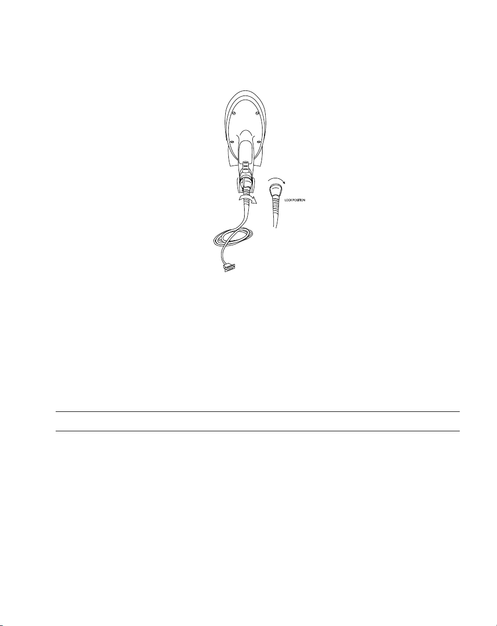
Installing the Cable
Insert the cable into the receptacle on the bottom of the scanner, and twist to the right as
shown:
Do not pull the trigger while installing a cable on the scanner.
Note:
1-2
Page 21
Getting Started
Figure 1-1. Installing the Cable
Switching Cables
Different cables are required for different hosts. To change the scanner cable:
1. Turn the cable counter-clockwise to unlock.
2. Pull the cable out of the receptacle on the bottom of the scanner.
3. Insert a new cable in the receptacle. Press the cable into the receptacle and twist to
the right.
Do not pull the trigger while installing a cable on the scanner.
Note:
Connecting Power
If your host does not provide power to the scanner, you will need to connect external power
to the scanner.
1. Connect the interface cable to the bottom of the scanner, as described in
the Cable
2. Connect the DC cable right-angle connector into the power port on the interface
cable. Plug the other end of the DC cable into the power supply.
3. Connect the AC line cord into the power supply. Plug the other end into a wall outlet.
.
Installing
1-3
Page 22
P 300STD/FZY/PRO Scanner Product Reference Guide
Connecting to a Host
The P 300 series scanners support a variety of host interfaces. The P 300FZY uses RS-232,
Synapse, Keyboard Wedge and Wand emulation to interface to a host system. The P 300PRO
uses RS-232 and Synapse to interface to a host system. This section describes how to make
each of these connections.
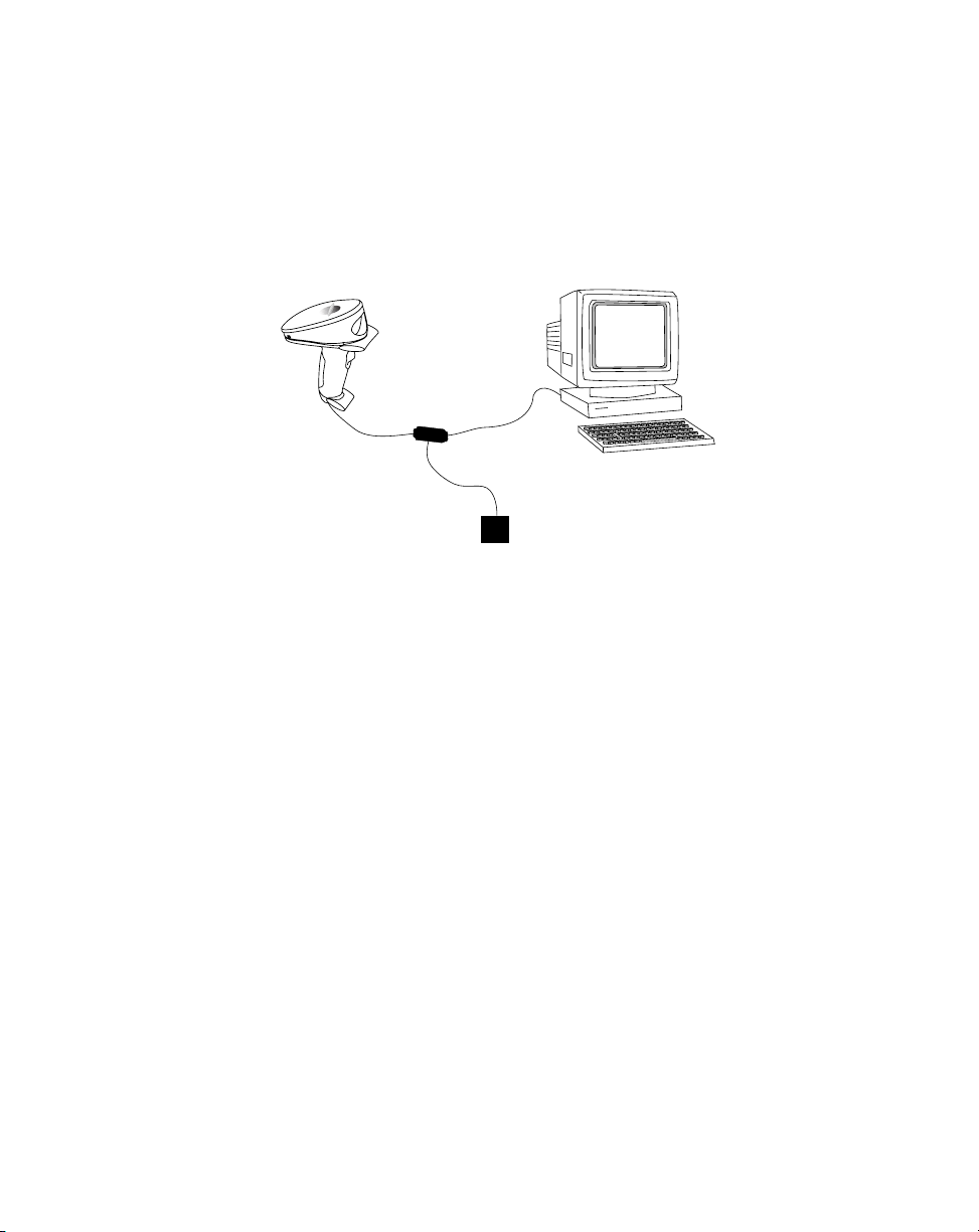
RS-232 Connection
Both the P 300FZY and P300PRO scanner use RS-232 to interface to a host system. This
connection can be made either directly from the scanner to the host, or indirectly through a
Synapse adapter cable to the host.
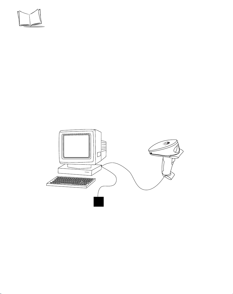
RS-232 Direct Connection
1. Connect the interface cable to the bottom of the scanner, as described in
the Cable
2. Connect the other end of the cable to the serial port on the host.
on page 1-2.
Installing
Figure 1-2. RS-232 Direct Connection
3. Plug one end of the power supply into the power receptacle on the RS-232 cable.
Plug the other end into a wall outlet.
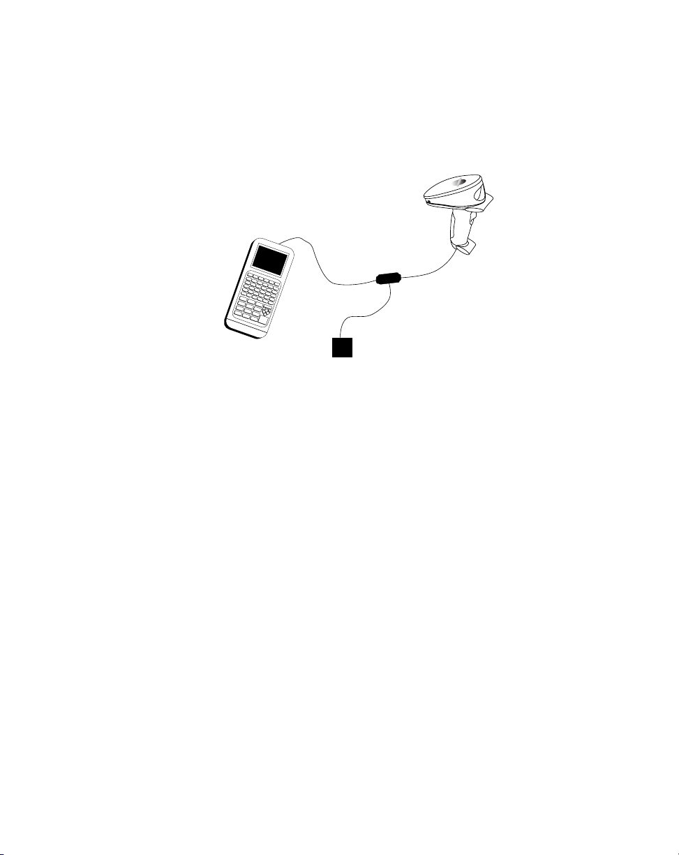
Wand Emulation Connection
To perform Wand emulation, the scanner can be connected to a portable data terminal, or a
controller which collects the data as wand data, and interprets it for the host.
1-4
Page 23
Getting Started
1. Connect the wand emulation interface cable (p/n 25-39803-01) to the bottom of the
scanner, as described in
2. Connect the other end of the interface cable into the COM port on the PDT or
Controller.
Figure 1-3. Wand Emulation Connection
3. Plug one end of the power cable into the power receptacle on the interface cable, and
plug the other end into a wall outlet.
Installing the Cable
on page 1-2.
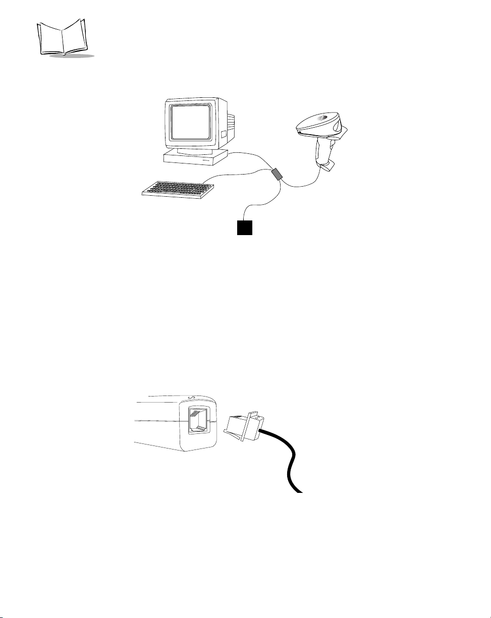
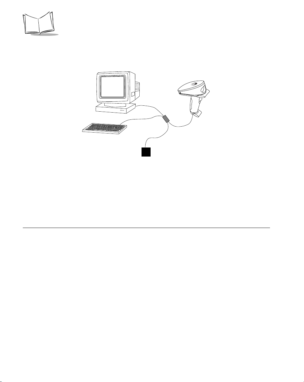
Keyboard Wedge Connection
When configured for keyboard wedge input, the host accepts input from the scanner as
keystrokes. The P 300 can perform keyboard wedge input using a keyboard wedge cable, or
via the Synapse cable.
To connect the keyboard wedge cable:
1. Connect the keyboard wedge interface cable (p/n 25-38699-01) to the bottom of the
scanner, as described in
Installing the Cable
on page 1-2.
1-5
Page 24
P 300STD/FZY/PRO Scanner Product Reference Guide
2. Connect the male end of the keyboard cable into the female end of the interface
cable. Connect the male end of the interface cable into the keyboard port on the host.
Figure 1-4. Keyboard Wedge Connection
3. Plug one end of the power cable into the power receptacle on the interface cable, and
plug the other end into a wall outlet.
Synapse Cable Connection
Symbol’s Synapse Smart Cables enable interfacing to a variety of hosts. The Synapse cable has
the built-in intelligence to detect the host to which it is connected.
1. Connect the Synapse adapter cable into the bottom of the scanner, as described in
Installing the Cable
2. Plug the other end of the Synapse adapter cable into the Synapse Smart Cable.
3. Connect the other end of the Synapse smart cable into the host.
1-6
on page 1-2.
Figure 1-5. Synapse Cable Connection
Page 25
Getting Started
RS-232 Connection using Synapse
1. Connect the interface cable to the bottom of the scanner, as described in
the Cable
2. Plug the other end of the interface cable into the Synapse Smart Cable.
3. Connect the other end of the Synapse Smart Cable to the host.
4. If needed, plug one end of the power supply into the power receptacle on the RS-232
cable. Plug the other end into a wall outlet.
5. If needed, plug one end of the power supply into the power receptacle on the RS-232
cable. Plug the other end into a wall outlet.
on page 1-2.
Figure 1-6. RS-232 Connection using Synapse
Installing
Keyboard Wedge Connection using Synapse
To connect the Synapse cable with Keyboard Wedge:
1. Connect the interface cable to the bottom of the scanner, as described in
the Cable
2. Connect the other end of the interface cable into the Synapse cable.
on page 1-2.
Installing
1-7
Page 26
P 300STD/FZY/PRO Scanner Product Reference Guide
3. The other end of the Synapse cable has 2 “flying leads”. Connect the male end of the
lead into the female end of the keyboard cable. Connect the male end of the lead into
the keyboard port on the host.
Figure 1-7. Keyboard Wedge via Synapse Connection
Programming the Scanner
Once the connections are made to the host, the scanner must be programmed to work with
that host. Refer to Chapter 2,
programming information.
Programming the Scanner
for the specific bar code
P 300PRO Scanning Mode Options
The P 300PRO supports several scanning options:
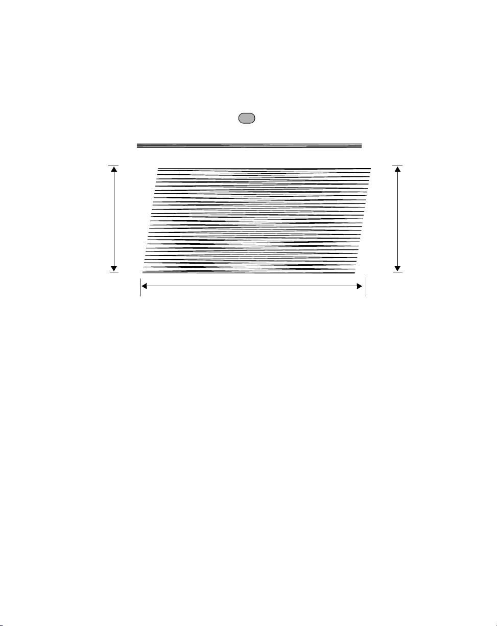
Smart Raster
The P 300PRO programmable “Smart Raster” capability causes the scanner to emit a raster
pattern dynamically adjusted to the particular PDF417 bar code’s height. To increase
scanning efficiency and decrease decode time, the scanner determines the height of the bar
code, opening at a size optimal for decoding that bar code.
In normal “Smart Raster” operation, a trigger pull causes a slab raster pattern to appear. If
the target is a 1-D bar code, the scanner decodes the symbol. If the target bar code is PDF417,
1-8
Page 27
Getting Started
the scanning patterns open up to a full, optimized raster pattern as soon as the scanner is
properly aligned over the bar code.
Aiming “Dot” Pattern
“Slab” Raster Pattern
Open Raster Pattern
Y- A x i s
Horizontal Displacement (X - Axis)
Y- A x i s
Figure 1-8. P 300PRO Aiming and Scanning Patterns
For best operation in Smart Raster mode, keep the scan pattern as parallel to the symbol’s
rows as possible, keep the scanner as still as possible, and hold the scanner at an angle which
does not give specular reflection. Likewise, the symbol should be in good condition.
Unless otherwise programmed, the P 300PRO operates with Smart Raster performance.
Slab Only Raster
Scanner activation creates a slab raster pattern which does not open vertically, regardless of
bar code type. This may provide optimal performance on small PDF417 and 1D bar codes.
Always Raster
When programmed to this option, the scanner directly opens the raster pattern to the
programmed height and at the programmed expansion speed when the trigger is pulled.
Programmable Raster
The user programs the height of the raster pattern and the rate at which it expands. Scanner
activation creates the slab raster pattern which only opens for PDF417 or MicroPDF417 bar
1-9
Page 28

P 300STD/FZY/PRO Scanner Product Reference Guide
codes, useful when decoding low-profile 1D and 2D bar codes where over-scanning is not
desired. Note that the height and expansion rate are directly, but not linearly, proportional to
their respective parameter values.
Aiming Modes
There are two aiming modes: aiming with a dot pattern, or with a slab raster pattern. Note
that aiming modes do not work with the Always Raster scanning option.
Aiming Dot Option
A trigger pull creates the single dot aiming pattern, which lasts for a fixed interval. This dot
can easily be seen in outdoor or high ambient light environments. A slab raster pattern or an
open raster pattern appears next, depending on the programmed scanning option. There are
two programmable timeout periods for this option — normal and extended.
Slab Raster Option
A trigger pull creates the slab raster pattern. If the target is a 1-D bar code, the pattern never
gets beyond a slab raster. If the target bar code is PDF417, the pattern opens up to an
optimized raster pattern as soon as the scanner is properly aligned over the bar code.
Scanning 1D Bar Codes
To scan a 1D bar code:
1. Make sure all connections are secure, and the symbol you want to scan is within the
scanning range (refer to Appendix D,
2. Aim the scanner at the symbol and press the trigger. The scanning beam remains on
for approximately 3.0 seconds (default) or until a successful decode.
The scanner has read the symbol when:
!
You hear a short, high tone beep (if the beeper is enabled).
!
The green LED on the scanner lights.
The green LED stays lit for one second or until the next trigger pull.
1-10
Technical Specifications
).
Page 29
Getting Started
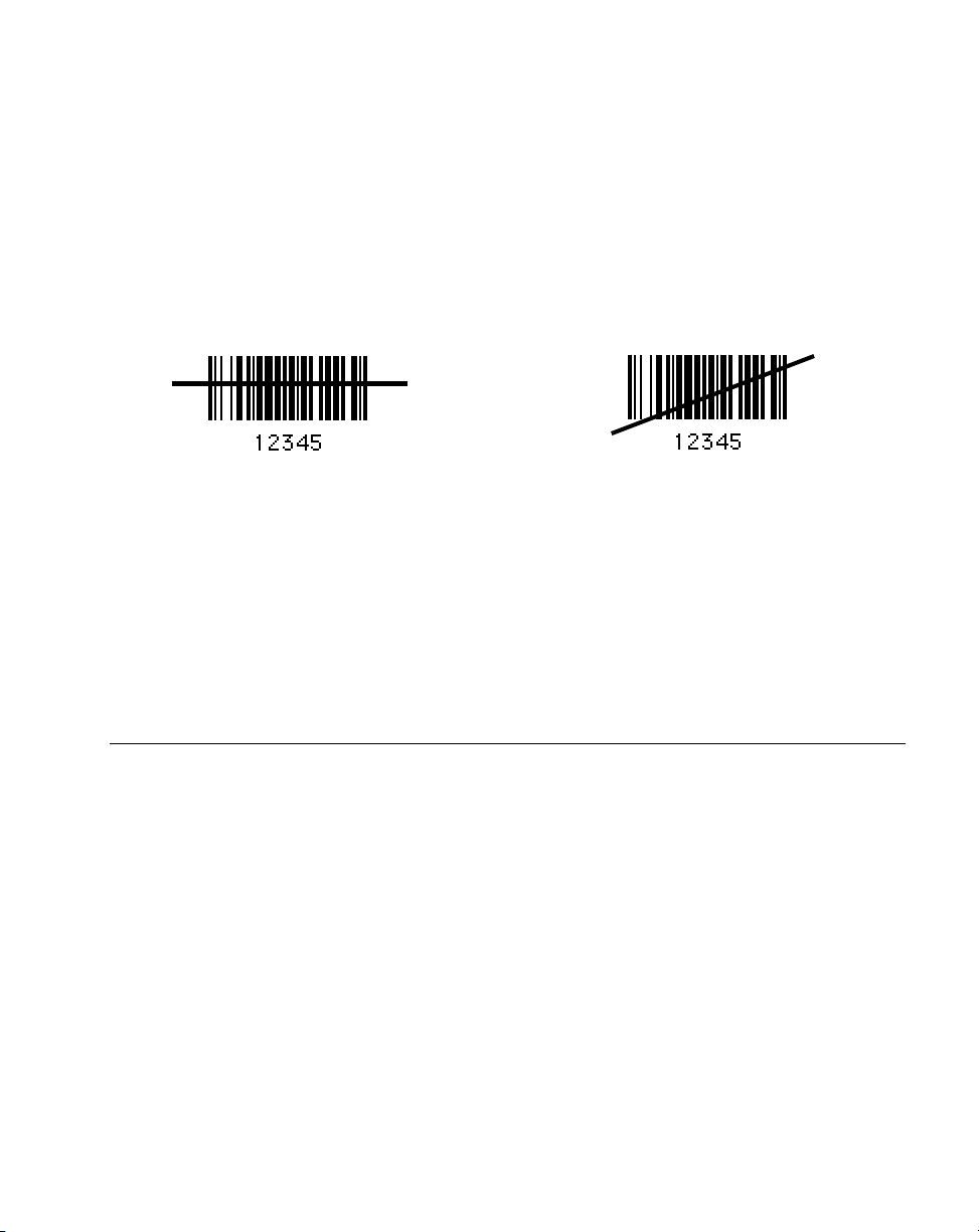
Aiming
Scan the Entire Symbol
!
Cross every bar and space of the symbol with the scan beam.
!
Hold the scanner further away for larger bar codes.
!
Hold the scanner closer for symbols with bars that are close together.
Right Wrong
Hold at an Angle
Do not hold the scanner directly over the bar code. Laser light reflecting
the scanner from the bar code is known as specular reflection. This strong light can
temporarily “blind” the scanner and make decoding difficult. The area where specular
reflection occurs is known as a “dead zone.”
You can tilt the scanner up to 65° forward or back and still achieve a successful decode Simple
practice quickly shows what tolerances to work within.
directly
back into
Scanning PDF417 (2D) Bar Codes (P300 PRO only)
PDF417 scanning is enabled by default in the P 300PRO scanner, and can be disabled or
enabled by scanning the corresponding parameter bar code in
page 2-85.
To scan a PDF417 bar code:
1. Aim the scanner at the PDF bar code and press the trigger.
2. Hold the trigger down and keep the scan line parallel to the rows of the symbol
overlapping the outside edges of the bar code by about 1/2” on each side.
The beam expands vertically to completely cover the bar code.
!
Check that PDF417 scanning is enabled.
!
Make sure the scan line extends at least 1/2” past the left and right edges of the bar
code.
Enable/Disable PDF417
on
1-11
Page 30
P 300STD/FZY/PRO Scanner Product Reference Guide
!
Hold the scanner closer for denser symbols, farther away for larger symbols.
!
Make sure you scan to the top and bottom rows of the symbol.
!
Be patient - it may take a few passes to decode the symbol.
The bar code has been completely decoded when you hear a tone, followed by a short, high
tone beep. The greed LED on the scanner lights. The green LED stays lit for two seconds or
until the next trigger pull.
1/2”
1/2”
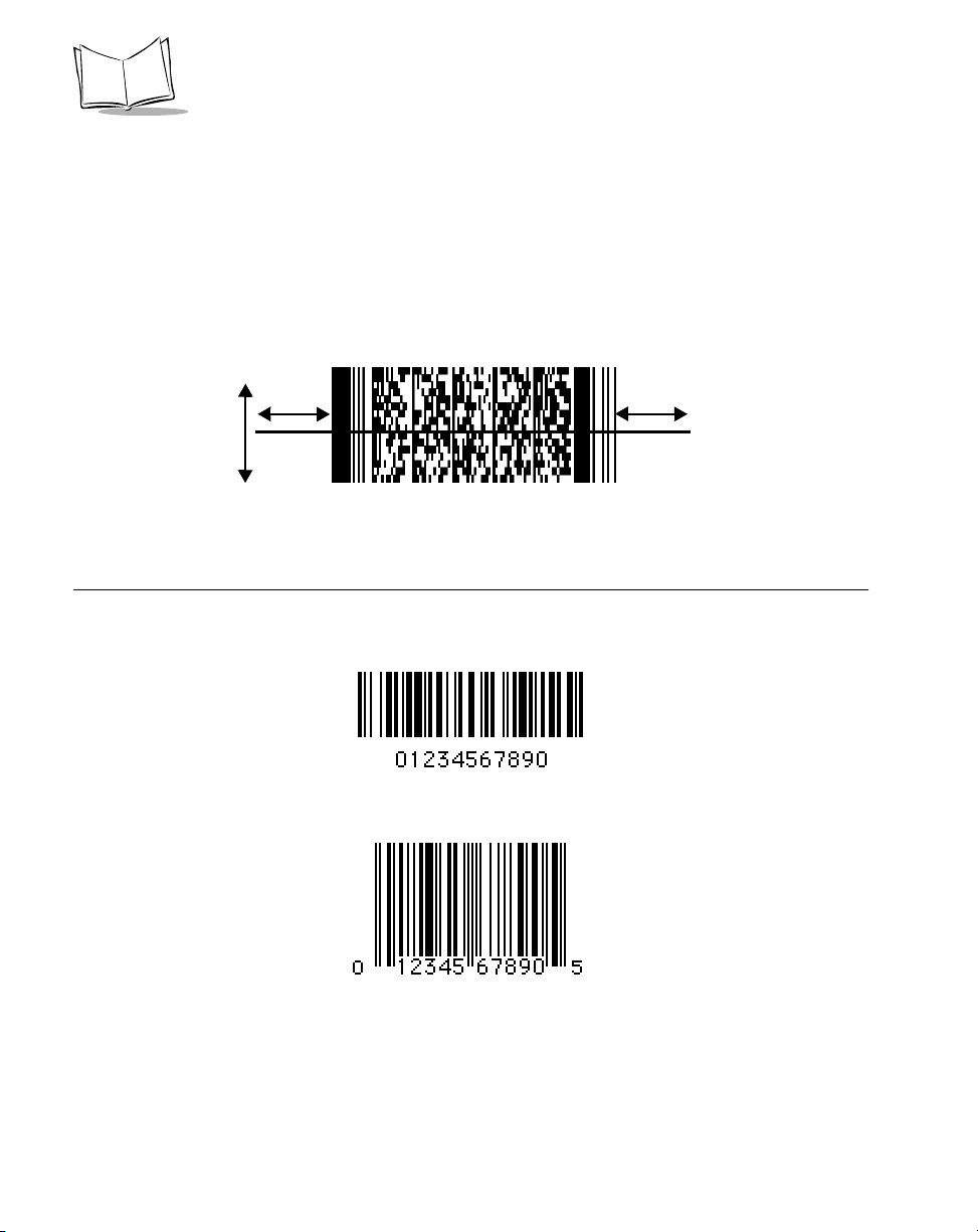
Test Symbols
To ensure your scanner is working properly, try scanning the following bar codes. If you have
trouble, refer to
Troubleshooting
on page 4-2.
CODE 128
1-12
UPC
Page 31

Symbol Technologies, Inc.
PDF417
Getting Started
“The Gettysburg Address”
PDF417
1-13
Page 32

P 300STD/FZY/PRO Scanner Product Reference Guide
Scan Stand Operation
Scan Stand operation allows hands-free scanning on the P 300FZY and P 300PRO. When the
scanner is placed in the stand, the scan pattern begins to blink on the surface below. The red
LED lights to indicate scanning activity.
To scan, present the symbol in the path of the scan pattern, but no more than 7” away. Make
sure the scan pattern extends at 3/4 inch beyond the symbol’s edges. When the symbol is
properly oriented, the scan pattern expands vertically to cover the symbol. The LED lights
green and a short, high-toned beep sounds to indicate successful decode.
After a successful decode, remove the symbol from the scan path. If the symbol does not
decode, or if the pattern does not expand, remove the symbol from the scan path and try
again. Make sure the bar code is on a clean, white, non-reflective surface.
1-14
Page 33

Getting Started
Beeper Indications
Table 1-1. Beeper Indicatio ns
Beeper Sequence Indication
Standard Use
Short high tone A bar code symbol was decoded (if decode beeper is
enabled).
Low tone, followed by short high tone A PDF417 bar code symbol was decoded (if decode
beeper is enabled).
4 Beeps - long low tone A transmission error has been detected in a scanned
symbol. The data is ignored. This occurs if a unit is not
properly configured. Check option settings.
5 Beeps - low tone Convert or format error.
Low/high/low tone ADF transmit error.
High/high/high/low tone RS-232 receive error.
Parameter Menu Scanning
Short high tone Correct entry scanned or correct menu sequence
performed.
Low/high tone Input error, incorrect bar code or “Cancel” scanned,
wrong entry, incorrect bar code programming sequence;
remain in program mode.
High/low tone Keyboard parameter selected. Enter value using bar code
keypad.
High/low/high/low tone Successful program exit with change in the parameter
setting.
1-15
Page 34

P 300STD/FZY/PRO Scanner Product Reference Guide
Table 1-1. Beeper Indications (Continued)
Beeper Sequence Indication
Code 39 Buffering
High/low tone New Code 39 data was entered into the buffer.
3 Beeps - long high tone Code 39 buffer is full.
Low/high/low tone The buffer was erased, or there was an attempt to
transmit an empty buffer. When the Code 39 buffer was
empty, the scanner read a command to clear or to
transmit a Code 39 buffer.
4 Beeps - long low tone Error in data transmission.
Low/high tone A successful transmission of buffered data.
Macro PDF
Table 1-2 provides beeper definitions for Macro PDF mode.
Table 1-2. Macro PDF Beeper Indications
Beeper Sequence Indication
Error
1 Low Long Hi-level decode error caused by incorrect
symbol.
2 Low Long File ID error. A bar code not in the current
MPDF sequence was scanned.
3 Low Long Out of memory. There is not enough buffer
space to store the current MPDF symbol.
4 Low Long Bad symbology. You scanned a 1-D or 2-D
bar code in an MPDF sequence, a duplicate
MPDF label, an incorrect sequence, or are
trying to transmit an empty or illegal
MPDF field.
5 Low Long Flushing buffer.
Fast Warble Successful parameter scanned.
Decode Beep Sequence
1-16
Page 35

Getting Started
Table 1-2. Macro PDF Beeper Indications
Beeper Sequence Indication
Single short Standard decode and transmit beep for all
symbols.
Double short MPDF symbol is buffered. A single beep
indicates transmission of the buffered data.
1-17
Page 36

P 300STD/FZY/PRO Scanner Product Reference Guide
1-18
Page 37

Chapter 2
Programming the Scanner
Introduction
The P 300 Series scanner can be programmed to perform various functions, or activate
different features. This chapter describes each feature and provides the programming bar
codes necessary for selecting these features for your scanner. Before programming, follow the
setup instructions in Chapter 1,
The P 300 Series scanner is shipped with the default settings shown in Table 2-1. You can
change these default values by scanning the appropriate bar codes included in this chapter.
These new values replace the standard default values in memory and are preserved even when
the scanner is powered down. The default parameter values can be recalled by scanning the
Set All Defaults
Even if the default parameters suit your needs, you must still select a terminal type. The
scanner automatically identifies the host type on power-up. It makes this determination
provided the host is powered-up before the scanner is attached to it. You must then select the
appropriate terminal type for that host.
bar code on page 2-9.
Getting Started
.
The following table lists the defaults for all parameters. If you wish to change any option,
scan the appropriate bar code(s). Several of the bar code parameters apply only to the
P300FZY, and others apply only to the P300PRO. This is noted in the parameter menus.
2-1
Page 38

P 300STD/FZY/PRO Scanner Product Reference Guide
Table 2-1. Default Table
Parameter P300FZY Default P 300PRO Default Page #
Set Default Parameter All Defaults All Defaults
Host Type RS-232 RS-232
Beeper Volume High N/A
Beeper Tone Medium High 2-14
Laser On Time 3.0 seconds 5.0 seconds
Power Mode Continuous Continuous
Trigger Mode N/A Level 2-17
Beep After Good Decode Enable Enable
Transmit “No Read” Message Disable Disable
Decode Buffering N/A Enable 2-19
LRC Checksum Disable Disable 2-20
Linear Code Type Security Levels 1 2
Bi-directional Redundancy Disable Disable
Autodiscriminate Response Time 1.0 second N/A 2-24
2-9
2-12
2-13
2-15
2-16
2-18
2-19
2-21
2-23
SCAN STAND OPTIONS
Time Delay to Low Power Mode N/A 30 seconds 2-25
Time Out Between Same Symbols N/A 0.6 seconds 2-26
Time Out Between Different Symbols N/A 0.0 seconds 2-26
UPC/EAN
UPC-A Enable Enable
2-28
2-2
Page 39

Programming the Scanner
Table 2-1. Default Table (continued)
Parameter P300FZY Default P 300PRO Default Page #
UPC-E Enable Enable
UPC-E1 Disable Disable 2-29
EAN-8 Enable Enable
EAN-13 Enable Enable
UPC Coupon Code Disable N/A 2-31
Bookland EAN Disable Disable
Decode UPC/EAN Supplementals Ignore Ignore
Decode UPC/EAN Supplemental
Redundancy
Transmit UPC-A Check Digit Enable Enable
Transmit UPC-E Check Digit Enable Enable
UPC-A Preamble System Character System Character
UPC-E Preamble System Character System Character
UPC-E1 Preamble System Character System Character 2-38
Convert UPC-E to A Disable Disable
77
2-28
2-30
2-30
2-32
2-33
2-34
2-35
2-35
2-36
2-37
2-39
Convert UPC-E1 to UPC-A Disable Disable 2-40
Transmit UPC-E1 Check Digit Enabled Enable 2-41
UPC/EAN Security Levels 0 0
EAN-8 Zero Extend Disable Disable
Convert EAN-8 to EAN-13 Type Disable Disable 2-45
2-42
2-44
2-3
Page 40

Code 128
P 300STD/FZY/PRO Scanner Product Reference Guide
Table 2-1. Default Table (continued)
Parameter P300FZY Default P 300PRO Default Page #
Code 128 Enable Enable
UCC/EAN-128 Enable Enable
ISBT-128 Enable Enable 2-48
Code 39
Code 39 Enable Enable
Trioptic Code 39 Disable Disable
Set Length(s) for Code 39 2 to 55 1-55
Code 39 Check Digit Verification Disable Disable
Transmit Code 39 Check Digit Disable Disable
Code 39 Full ASCII Conversion Disable Disable
Buffer Code 39 Disable N/A
Convert Code 39 to Code 32 Disable Disable 2-60
Code 32 Prefix Disable Enabled 2-61
Code 93
2-46
2-47
2-50
2-51
2-53
2-54
2-55
2-56
2-57
Code 93 Disable Disable
Set Length(s) for Code 93 4-55 4-55
Interleaved 2 of 5
Interleaved 2 of 5 Enable Disable
Set Length(s) for I 2 of 5 14 14
I 2 of 5 Check Digit Verification Disable Disable
2-4
2-62
2-63
2-65
2-66
2-68
Page 41

Programming the Scanner
Table 2-1. Default Table (continued)
Parameter P300FZY Default P 300PRO Default Page #
Transmit I 2 of 5 Check Digit Disable Disable
Convert I 2 of 5 to EAN 13 Disable Disable
Discrete 2 of 5
Discrete 2 of 5 Disable Disable
Set Length(s) for D 2 of 5 12 12
Codabar
Codabar Disable Disable
Set Lengths for Codabar 5-55 5-55
CLSI Editing Disable Disable
NOTIS Editing Disable Disable
MSI Plessey
MSI Plessey Disable Disable
Set Length(s) for MSI Plessey Any Length Any Length
MSI Plessey Check Digits One One
2-69
2-70
2-71
2-72
2-74
2-75
2-77
2-78
2-79
2-81
2-82
Transmit MSI Plessey Check Digit Disable Disable
MSI Plessey Check Digit Algorithm Mod 10/Mod 10 Mod10/Mod10
PDF
Enable/Disable PDF417 N/A Enable 2-85
Scanning Mode N/A Smart Raster
Raster Height N/A 15
Raster Expansion N/A 11
2-83
2-84
2-89
2-90
2-90
2-5
Page 42

P 300STD/FZY/PRO Scanner Product Reference Guide
Table 2-1. Default Table (continued)
Parameter P300FZY Default P 300PRO Default Page #
Aiming Mode N/A Slab Raster
Micro PDF
Enable/Disable Micro PDF N/A Disable
Code 128 Emulation N/A Enable 2-87
UCC/EAN-128 Emulation N/A Ignore 2-88
Data Options
Transmit Code ID Character None None
Pause Duration 0 0
Prefix/Suffix Values 7013
(<CR/LF> for
serial)
Scan Data Transmission Format Data as is Data As Is
RS-232C
RS-232 Host Type Standard Standard
Baud Rate 9600 9600
Enter
2-92
2-86
2-94
2-95
2-96
2-97
2-12
2-100
Parity None None
Check Parity Do Not Check Check
Hardware Handshaking None None
Software Handshaking None None
Host Serial Response Time-out 2.0 Sec. 2.0 Sec.
RTS Line State Low Low
Stop Bit Select 1 1
2-6
2-101
2-102
2-103
2-104
2-106
2-107
2-107
Page 43

Programming the Scanner
Table 2-1. Default Table (continued)
Parameter P300FZY Default P 300PRO Default Page #
ASCII Format 8-Bit 8-Bit
Beep on <BEL> Disable Disable
Intercharacter Delay 0 0
Wand Parameters
Wand Host Interface Symbollink N/A
Wand Emulator Bar Output Bar High N/A 2-111
Variable Leading Margin 80 ms. N/A 2-112
Convert All to Code 39 Disable N/A 2-114
Keyboard Wedge Parameters
Host Type IBM PC/AT N/A 2-115
National Keyboard Type North American N/A 2-116
Fast Transmit Enabled N/A 2-118
Intercharacter Delay 0 N/A 2-119
Convert Control Characters Disable N/A 2-119
2-108
2-108
2-109
2-110
MacroPDF Parameters
MacroPDF Transmit/Decode Mode
Symbols
Transmit Symbols in Codeword
Format
Escape Characters N/A None
Delete Character Set ECIs N/A Enable
N/A Buffer all Symbols;
Transmit Macro PDF
when complete
N/A Disable
2-124
2-126
2-128
2-129
2-7
Page 44

P 300STD/FZY/PRO Scanner Product Reference Guide
Table 2-1. Default Table (continued)
Parameter P300FZY Default P 300PRO Default Page #
ECI Decoder N/A Enable
Transmit Unknown Codewords N/A Disable
Transmit MacroPDF User-Selectable
Fields
Flush Macro Buffer N/A Disable
Abort MacroPDF Entry N/A Disable
Transmit Macro PDF User-Selected Field:
Transmit File Name N/A Disable 2-133
Transmit Block Count N/A Disable 2-133
Transmit Time Stamp N/A Disable 2-133
Transmit Sender N/A Disable 2-133
Transmit Addresses N/A Disable 2-134
Transmit File Size N/A Disable 2-134
Transmit Checksum N/A Disable 2-134
Transmit Macro PDF Control Header N/A Disable 2-134
N/A Disable
2-130
2-131
2-132
2-135
2-135
Last Block Marker N/A Disable 2-134
2-8
Page 45

Programming the Scanner
Set Default Parameter
Scanning this bar code returns all parameters to the default values listed in Table 2-1 on page
2-2.
Set All Defaults
2-9
Page 46

P 300STD/FZY/PRO Scanner Product Reference Guide
Host Type
RS-232C Host Types
Three RS-232C hosts are set up with their own parameter default settings (Table 2-2.)
Selecting the ICL, Fujitsu, or Nixdorf RS-232C terminal sets the defaults listed below. These
defaults take precedence over standard defaults. So if you select Fujitsu RS-232C, then select
the standard defaults, the Fujitsu defaults still take precedence.
Table 2-2. Terminal-Specific RS-232C
Parameter Standard ICL FUJITSU NIXDORF
Mode A/
Mode B
Transmit Code ID No Yes Yes Yes
Data Transmission Format Data as is Data/Suffix Data/Suffix Data/Suffix
Suffix CR/LF (7013) CR (1013) CR (1013) CR (1013)
Baud Rate 9600 9600 9600 9600
Parity None Even None Odd
Hardware Handshaking None RTS/CTS
Option 3
Software Handshaking None None None None
Serial Response Time-out 2 Sec. 9.9 Sec. 2 Sec. indefinite
Stop Bit Select One One One One
ASCII Format 8-Bit 8-Bit 8-Bit 8-Bit
Beep On <BEL> Disabled Disabled Disabled Disabled
RTS Line State Low High Low *Low = No
*In the Nixdorf Mode B, if CTS is Low, scanning is disabled. When CTS is High, the user can scan
bar codes.
None RTS/CTS
Option 3
data to send
2-10
Page 47

Programming the Scanner
Host Type
RS-232C Host Types
Selecting the ICL, Fujitsu, or Nixdorf RS-232C terminal enables the transmission of the code
ID characters listed in Table 2-3. These code ID characters are not programmable; do not
enable the Transmit Code ID feature.
Table 2-3. Terminal Specific Code ID Characters
ICL FUJITSU NIXDORF
UPC-A A A A
UPC-E E E C0
EAN-8 FF FF B
EAN-13 F F A
Code 39 C <len> None M
Codabar N <len> None N
Code 128 L <len> None K
I 2 of 5 I <len> None I
Code 93 None None L
D 2 of 5 H <len> None H
UCC/EAN 128 L <len> None P
MSI/Plessey None None O
Bookland EAN F F A
Trioptic None None None
2-11
Page 48

P 300STD/FZY/PRO Scanner Product Reference Guide
Host Type
RS-232C Host Types
To select an RS-232C host interface, scan one of the following bar codes.
Standard RS-232C
ICL RS-232C
2-12
Nixdorf RS-232C Mode A
Nixdorf RS-232C Mode B
Fujitsu RS-232C
Page 49

Beeper Volume
Programming the Scanner
To select a beeper volume, scan the
Low Volume, Medium Volume
Low Volume
Medium Volume
High Volume
High Volume
, or
bar code.
2-13
Page 50

P 300STD/FZY/PRO Scanner Product Reference Guide
Beeper Tone
This parameter sets the decode beep frequency or tone — low, medium, or high.
This parameter is used by the P300 FZY and PRO only
Note:
Low Frequency
Medium Frequency
2-14
High Frequency
Page 51

Programming the Scanner
Laser On Time
This parameter sets the maximum time decode processing continues during a scan attempt.
It is programmable in 0.1 second increments from 0.5 to 9.9 seconds.
To set a Laser On Time, scan the bar code below. Next scan two numeric bar codes beginning
on page 2-120 that correspond to the desired time on. Single digit numbers must have a
leading zero. For example, to set a Time On of .5 seconds, scan the bar code below, then scan
the “0” and “5” bar codes. If you make an error, or wish to change your selection, scan
CANCEL
on page 2-122.
Laser On Time
2-15
Page 52

P 300STD/FZY/PRO Scanner Product Reference Guide
Power Mode
This parameter determines whether or not power remains on after a decode attempt. When
in low power mode, the scanner enters low power consumption mode to preserve battery
life after each decode attempt. When in continuous power mode, power remains on after
each decode attempt.
Continuous On
Low Power
2-16
Page 53

Programming the Scanner
Tri gge r Mo de
This parameter controls scanner triggering. “Trigger” refers to an external hardware trigger
or a scanner trigger.
This parameter is available on the P 300PRO only.
Note:
!
If Level is selected, a trigger pull activates the laser and decode processing. The laser
remains on and decode processing continues until a successful decode, the trigger is
released, or the Decode Attempt Duration is reached.
!
If Pulse is selected, a trigger pull activates the laser and decode processing. The laser
remains on and decode processing continues until a successful decode or the Decode
Attempt Duration is reached.
Select either Level or Pulse trigger mode.
Level
Pulse
2-17
Page 54

P 300STD/FZY/PRO Scanner Product Reference Guide
Beep After Good Decode
Scan this symbol if you want the scanner to beep after a good decode.
Beep After Good Decode
Scan this symbol if you do not want the scanner to beep after a good decode. The beeper still
operates during parameter menu scanning and indicates error conditions.
Do Not Beep After Good Decode
2-18
Page 55

Programming the Scanner
Transmit “No Read” Message
When enabled, the scanner transmits “NR” if it does not decode a symbol. Any enabled
prefixes or suffixes are appended around this message. When disabled, if a symbol does not
read, nothing is sent to the host.
Enable No Read
Disable No Read
Decode Buffering
This option permits the scanner to store decode data until the host device is ready to receive
them. If the scanner reaches its capacity to store decoded symbols before the host is ready,
subsequent trigger pulls have no effect until a buffer is available.
Enable Decode Buffering
Disable Decode Buffering
2-19
Page 56

P 300STD/FZY/PRO Scanner Product Reference Guide
LRC Checksum
Enabling this option allows for appending an LRC checksum character at the end of a decode
transmission.
When an LRC checksum is enabled, the format of output data is as follows: <STX>
<DATA...> <ETX> <LRC>. If <DATA...> contains the special characters STX, ETX, and
DLE, a DLE character is used as an escape character and is added before each of those
characters so that the receiving side knows not to interpret the special characters in the data
as control characters. The LRC character is the exclusive OR of all characters except for the
LRC character itself.
Enable LRC Checksum
2-20
Disable LRC Checksum
Page 57

Programming the Scanner
Linear Code Type Security Level
(Does not apply to Code 128)
The P 300 Series scanner offers four levels of decode security for linear code types (e.g. Code
39, Interleaved 2 of 5). Select a higher security level for low quality bar codes. As security
levels increase, the scanner’s aggressiveness decreases.
Select the security level appropriate for your bar code quality.
Linear Security Level 1
The following code types must be successfully read twice before being transmitted.
Code Type Length
Codabar All
MSI Plessey 4 or less
D 2 of 5 8 or less
I 2 of 5 8 or less
Linear Security Level 1
Linear Security Level 2
All code types must be successfully read twice before being transmitted.
Linear Security Level 2
2-21
Page 58

P 300STD/FZY/PRO Scanner Product Reference Guide
Linear Security Level 3
Code types other than the following must be successfully read twice before being transmitted.
The following codes must be read three times:
Code Type Length
MSI Plessey 4 or less
D 2 of 5 8 or less
I 2 of 5 8 or less
Codabar 8 or less
Linear Security Level 3
Linear Security Level 4
All code types must be successfully read three times before being transmitted
Linear Security Level 4
2-22
Page 59

Bi-directional Redundancy
Programming the Scanner
This parameter is only valid when a
enabled. When this parameter is enabled, a bar code must be successfully scanned in both
directions (forward and reverse) before being decoded.
Enable Bi-directional Redundancy
Disable Bi-directional Redundancy
Linear Code Type Security Level
(see page 2-21) is
2-23
Page 60

P 300STD/FZY/PRO Scanner Product Reference Guide
Autodiscriminate Response Time
This parameter extends the length of time during which the scanner tries to detect which host
it is connected to on power up.
Note: When connected to an LS 5700/5800 scanner, the 5 second option
must be used.
1 second
2-24
5 seconds
Page 61

Programming the Scanner
Scan Stand Options
Time Delay to Low Power Mode
This parameter is available on the P 300PRO only.
Note:
For extending laser life in scan stand mode, select the time the scanner remains active
following a successful decode. Selectable options include 30 seconds, 1 minute, 2 minutes, 3
minutes. To awaken the scanner in low power mode, present a symbol to the scan path. A
successful decode restores it to normal blinking.
30 Second Delay
2 Minute Delay
1 Minute Delay
3 Minute Delay
2-25
Page 62

P 300STD/FZY/PRO Scanner Product Reference Guide
Timeout Between Decodes
This parameter is available on the P 300PRO only.
Note:
Timeout Between Decodes, Same Symbol is used in scan stand mode to prevent the beeper
from continuously beeping when a symbol is left in the scanner’s field of view. It is
programmable in 0.1 second increments from 0.0 to 9.9 seconds. The recommended interval
is 0.6 seconds.
Timeout Between Decodes, Different Symbols is used in scan stand mode to prevent the
beeper from beeping when a different symbol appears in the scanner’s field of view before the
timeout period between decodes has expired. This is programmable in 0.1 second increments
from 0.0 to 9.9 seconds. The recommended value is 0.0 seconds.
Select the timeouts between decodes for the same or different symbols.
1. Scan the option bar code you wish to set.
2. Scan two bar codes on the next page which correspond to the desired interval, in 0.1
second increments.
3. If you make an error, or wish to change your selection, scan CANCEL.
2-26
Timeout Between Decodes -
The Same Symbol
Timeout Between Decodes -
Different Symbols
Page 63

Timeout Between Decodes (Continued)
Programming the Scanner
0
2
4
6
1
3
5
7
8
Cancel
9
2-27
Page 64

P 300STD/FZY/PRO Scanner Product Reference Guide
Enable/Disable UPC-E/UPC-A
To enable or disable UPC-E or UPC-A, scan the appropriate bar code below.
Enable UPC-E
Disable UPC-E
2-28
Enable UPC-A
Disable UPC-A
Page 65

Programming the Scanner
Enable/Disable UPC-E1
To enable or disable UPC-E1, scan the appropriate bar code below.
Enable UPC-E1
Disable UPC-E1
2-29
Page 66

P 300STD/FZY/PRO Scanner Product Reference Guide
Enable/Disable EAN-8/EAN-13
To enable or disable EAN-8 or EAN-13, scan the appropriate bar code below.
Enable EAN-8
Disable EAN-8
2-30
Enable EAN-13
Disable EAN-13
Page 67

Programming the Scanner
UPC Coupon Code
To enable or disable UPC Coupon Code, scan one of the following bar codes:
Enable UPC/EAN Coupon Code
Disable UPC/EAN Coupon Code
2-31
Page 68

P 300STD/FZY/PRO Scanner Product Reference Guide
Enable/Disable Bookland EAN
To enable or disable EAN Bookland, scan the appropriate bar code below.
Enable Bookland EAN
Disable Bookland EAN
2-32
Page 69

Programming the Scanner
Decode UPC/EAN Supplementals
Supplementals are additionally appended characters (2 or 5) according to specific code
format conventions (e.g., UPC A+2, UPC E+2, EAN 8+2). Three options are available.
!
If UPC/EAN with supplemental characters is selected, UPC/EAN symbols without
supplemental characters are not decoded.
!
If UPC/EAN without supplemental characters is selected, and the P 300 Series
scanner is presented with a UPC/EAN plus supplemental symbol, the UPC/EAN
is decoded and the supplemental characters ignored.
!
An autodiscriminate option is also available. If this option is selected, choose an
appropriate
A value of 5 or more is recommended.
Note: To minimize the risk of invalid data transmission, select whether to
Decode UPC/EAN Supplemental Redundancy
read or ignore supplemental characters.
value from the next page.
Decode UPC/EAN with Supplementals
Ignore UPC/EAN with Supplementals
Autodiscriminate UPC/EAN Supplemental
2-33
Page 70

P 300STD/FZY/PRO Scanner Product Reference Guide
Decode UPC/EAN Supplemental Redundancy
With Autodiscriminate UPC/EAN Supplementals selected, this option adjusts the number of
times a symbol without supplementals is decoded before transmission. The range is from two
to twenty times. Five or above is recommended when decoding a mix of UPC/EAN symbols
with and without supplementals, and the autodiscriminate option is selected.
Scan the bar code below to select a decode redundancy value. Next scan two numeric bar
codes beginning on page 2-120. Single digit numbers must have a leading zero. If you make
an error, or wish to change your selection, scan
Decode UPC/EAN
Supplemental Redundancy
CANCEL
on page 2-122.
2-34
Page 71

Programming the Scanner
Transmit UPC-A/UPC-E Check Digit
Scan the appropriate bar code below to transmit the symbol with or without the UPC-A or
UPC-E check digit.
Transmit UPC-A Check Digit
Do Not Transmit UPC-A Check Digit
Transmit UPC-E Check Digit
Do Not Transmit UPC-E Check Digit
2-35
Page 72

P 300STD/FZY/PRO Scanner Product Reference Guide
UPC-A Preamble
Three options are given for lead-in characters for UPC-A symbols transmitted to the host
device: transmit system character only, transmit system character and country code (“0” for
USA), and no preamble transmitted. The lead-in characters are considered part of the symbol.
No Preamble
(<DATA>)
System Character
(<SYSTEM CHARACTER> <DATA>)
2-36
System Character & Country Code
(< COUNTRY CODE> <SYSTEM CHARACTER> <DATA>)
Page 73

Programming the Scanner
UPC-E Preamble
Three options are given for lead-in characters for UPC-E symbols transmitted to the host
device: transmit system character only, transmit system character and country code (“0” for
USA), and no preamble transmitted. The lead-in characters are considered part of the symbol.
No Preamble
(<DATA>)
System Character
(<SYSTEM CHARACTER> <DATA>)
System Character & Country Code
(< COUNTRY CODE> <SYSTEM CHARACTER> <DATA>)
2-37
Page 74

P 300STD/FZY/PRO Scanner Product Reference Guide
UPC-E1 Preamble
Three options are given for lead-in characters for UPC-E1 symbols transmitted to the host
device: transmit system character only, transmit system character and country code (“0” for
USA), and no preamble transmitted. The lead-in characters are considered part of the symbol.
No Preamble
System Character
2-38
System Character and Country Code
Page 75

Programming the Scanner
Convert UPC-E to UPC-A
This parameter converts UPC-E (zero suppressed) decoded data to UPC-A format before
transmission. After conversion, data follows UPC-A format and is affected by UPC-A
programming selections (e.g., Preamble, Check Digit).
Scanning
UPC-E (zero suppressed) decoded data.
DO NOT CONVERT UPC-E TO UPC-A
Convert UPC-E to UPC-A
Do Not Convert UPC-E to UPC-A
allows you to transmit
(Enable)
(Disable)
2-39
Page 76

P 300STD/FZY/PRO Scanner Product Reference Guide
Convert UPC-E1 to UPC-A
This parameter converts UPC-E1 decoded data to UPC-A format before transmission. After
conversion, data follows UPC-A format and is affected by UPC-A programming selections
(e.g., Preamble, Check Digit).
Scanning
decoded data.
DO NOT CONVERT UPC-E1 TO UPC-A
allows you to transmit UPC-E1
Convert UPC-E1 to UPC-A
Do Not Convert UPC-E1 to UPC-A
2-40
Page 77

Programming the Scanner
Transmit UPC-E1 Check Digit
Scan the appropriate bar code below to transmit the symbol with or without the UPC-E1
check digit
Transmit UPC-E1 Check Digit
Do Not Transmit UPC-E1 Check Digit
2-41
Page 78

P 300STD/FZY/PRO Scanner Product Reference Guide
UPC/EAN Security Level
The P 300 Series scanner offers four levels of decode security for UPC/EAN bar codes. Select
a higher level of security for poor quality bar codes. There is an inverse relationship between
security and scanner aggressiveness, so be sure to choose only that level of security necessary
for your application.
UPC/EAN Security Level 0
This default setting allows the scanner to operate in its most aggressive state, while providing
sufficient security in decoding “in-spec” UPC/EAN bar codes.
UPC/EAN Security Level 0
UPC/EAN Security Level 1
As bar code quality levels diminish, certain characters become prone to misdecodes before
others (i.e., 1, 2, 7, 8). If you are experiencing misdecodes of poorly printed bar codes, and
the mis-decodes are limited to these characters, select this security level.
2-42
UPC/EAN Security Level 1
Page 79

Programming the Scanner
UPC/EAN Security Level 2
If you are experiencing misdecodes of poorly printed bar codes, and the misdecodes are not
limited to characters 1, 2, 7, and 8, select this security level.
UPC/EAN Security Level 2
UPC/EAN Security Level 3
If you have tried Security Level 2, and are still experiencing misdecodes, select this security
level. Be advised, selecting this option is an extreme measure against misdecoding severely out
of spec bar codes, and security significantly impairs the decoding ability of the scanner. If this
level of security is necessary, try to improve the quality of your bar codes.
UPC/EAN Security Level 3
2-43
Page 80

P 300STD/FZY/PRO Scanner Product Reference Guide
EAN-8 Zero Extend
This parameter adds five leading zeros to decoded EAN-8 symbols to make them compatible
in format to EAN-13 symbols.
Enable EAN-8 Zero
Extend
Disable EAN-8 Zero
Extend
2-44
Page 81

Programming the Scanner
Convert EAN-8 to EAN-13 Type
When EAN Zero Extend is enabled, this parameter gives you the option of labeling the
extended symbol as either an EAN-13 bar code, or an EAN-8 bar code. This affects
Code ID Character
When EAN Zero Extend is disabled, this parameter has no effect on bar code data.
DECODE_DATA
and
message.
Ty pe Is EA N - 8
Typ e Is EA N- 13
Transmit
2-45
Page 82

P 300STD/FZY/PRO Scanner Product Reference Guide
Enable/Disable Code 128
To enable or disable Code 128, scan the appropriate bar code below.
Enable Code 128
Disable Code 128
2-46
Page 83

Programming the Scanner
Enable/Disable UCC/EAN-128
To enable or disable UCC/EAN-128, scan the appropriate bar code below. (See Appendix A,
Programming Reference
for details on UCC/EAN128.)
Enable UCC/EAN-128
Disable UCC/EAN-128
2-47
Page 84

P 300STD/FZY/PRO Scanner Product Reference Guide
Enable/Disable ISBT 128
To enable or disable ISBT 128, scan the appropriate bar code below.
Enable ISBT 128
Disable ISBT 128
2-48
Page 85

Programming the Scanner
Lengths for Code 128
No length setting is required for Code 128. The default setting is Any Length.
2-49
Page 86

P 300STD/FZY/PRO Scanner Product Reference Guide
Enable/Disable Code 39
To enable or disable Code 39, scan the appropriate bar code below.
Enable Code 39
Disable Code 39
2-50
Page 87

Programming the Scanner
Enable/Disable Trioptic Code 39
Trioptic Code 39 symbols always contain six characters. To enable or disable Trioptic Code
39, scan the appropriate bar code below.
Enable Trioptic Code 39
Disable Trioptic Code 39
Note: Trioptic Code 39 and Code 39 Full ASCII cannot be enabled
simultaneously. If you get an error beep when enabling Trioptic Code
39, disable Code 39 Full ASCII and try again.
2-51
Page 88

P 300STD/FZY/PRO Scanner Product Reference Guide
Set Lengths for Code 39
Lengths for Code 39 may be set for any length, one or two discrete lengths, or lengths within
a specific range. The length of a code refers to the number of characters (i.e., human readable
characters), the code contains, including check digit(s) . If Code 39 Full ASCII is enabled,
Length Within a Range
Any Length
or
are the preferred options.
One Discrete Length
selected length. For example, if you select
Code 39 symbols containing 14 characters are decoded. Numeric bar codes begin on page
2-120. If you make an error or wish to change your selection, scan
122.
Two Discrete Lengths
selected lengths. For example, if you select
2, 1, 4
, only Code 39 symbols containing 2 or 14 characters are decoded. Numeric bar
codes begin on page 2-120. If you make an error or wish to change your selection, scan
CANCEL
on page 2-122.
- This option allows you to decode only those codes containing a
Code 39 One Discrete Length
Code 39 - One Discrete Length
- This option allows you to decode only those codes containing two
Code 39 Two Discrete Lengths
Code 39 - Two Discrete Lengths
, then scan 1, 4, only
CANCEL
on page 2-
, then scan 0,
2-52
Page 89

Programming the Scanner
Length Within Range
- This option allows you to decode a code type within a specified
range. For example, to decode Code 39 symbols containing between 4 and 12 characters,
first scan
Code 39 Length Within Range
. Then scan 0, 4, 1, and 2 (single digit numbers must
always be preceded by a leading zero). Numeric bar codes begin on page 2-120. If you make
an error or wish to change your selection, scan
Code 39 - Length within Range
Any Length
- Scanning this option allows you to decode Code 39 symbols containing any
CANCEL
on page 2-122.
number of characters.
Code 39 - Any Length
2-53
Page 90

P 300STD/FZY/PRO Scanner Product Reference Guide
Code 39 Check Digit Verification
When enabled, this parameter checks the integrity of a Code 39 symbol to ensure it complies
with specified algorithms.
Only those Code 39 symbols which include a modulo 43 check digit are decoded when this
parameter is enabled.
Enable Code 39 Check Digit
Disable Code 39 Check Digit
2-54
Page 91

Programming the Scanner
Transmit Code 39 Check Digit
Scan this symbol if you want to transmit the check digit with the data.
Transmit Code 39 Check Digit
(Enable)
Do Not Transmit Code 39 Check Digit
(Disable)
2-55
Page 92

P 300STD/FZY/PRO Scanner Product Reference Guide
Enable/Disable Code 39 Full ASCII
To enable or disable Code 39 Full ASCII, scan the appropriate bar code below.
When enabled, the ASCII character set assigns a code to letters, punctuation marks,
numerals, and most control keystrokes on the keyboard.
The first 32 codes are non-printable and are assigned to keyboard control characters such as
BACKSPACE and RETURN. The other 96 are called printable codes because all but SPACE
and DELETE produce visible characters.
Code 39 Full ASCII interprets the bar code special character ($ + % /) preceding a Code 39
character and assigns an ASCII character value to the pair. For example, when Code 39 Full
ASCII is enabled and a +B is scanned, it is interpreted as b, %J as ?, and $H emulates the
keystroke
ENTER
The scanner does not autodiscriminate between Code 39 and Code 39 Full ASCII.
BACKSPACE
. Refer to Table C-1 on page C-1.
. Scanning
ABC$M
outputs the keystroke equivalent of
ABC
Enable Code 39 Full ASCII
Disable Code 39 Full ASCII
Note: Trioptic Code 39 and Code 39 Full ASCII cannot be enabled
simultaneously. If you get an error beep when enabling Trioptic Code
39, disable Code 39 Full ASCII and try again.
2-56
Page 93

Programming the Scanner
Code 39 Buffering (Scan & Store)
When you select the Buffer Code 39 option, all Code 39 symbols having a leading space as a
first character are temporarily buffered in the unit to be transmitted later. The leading space
is not buffered.
Decode of a valid Code 39 symbol with no leading space causes transmission in sequence of
all buffered data in a first-in first-out format, plus transmission of the “triggering” symbol.
See the following pages for further details.
When the Do Not Buffer Code 39 option is selected, decoded Code 39 symbols without
leading spaces are transmitted immediately.
Scan and Store affects Code 39 decodes only. If you select scan and store, we recommend that
you configure the scanner to decode Code 39 symbology only.
Buffer Code 39
(Enable)
Do Not Buffer Code 39
(Disable)
While there is data in the transmission buffer, disabling Code 39 buffering via the
parameter menu is not allowed. The buffer holds 200 bytes of information.
To allow disabling of Code 39 buffering, first force the buffer transmission (see
Buffer
) or clear the buffer. Both the
are length 1.
Be sure Code 39 length is set to include length 1.
CLEAR BUFFER
TRANSMIT BUFFER
and
Transmit
bar codes
2-57
Page 94

P 300STD/FZY/PRO Scanner Product Reference Guide
Buffer Data
To buffer data, Code 39 buffering must be enabled, and a symbol must be read with a space
immediately following the start pattern.
!
Unless symbol overflows the transmission buffer, the scanner gives a low/high beep
to indicate successful decode and buffering. See
!
The scanner adds the message, excluding the leading space, to the transmission
Overfilling Transmission Buffer
.
buffer.
!
No transmission occurs.
Clear Transmission Buffer
To clear the transmission buffer, read a symbol which contains only a start character, a dash
(minus), and a stop character.
!
The scanner issues a short high/low/high beep to signal that the transmission buffer
has been erased, and no transmission has occurred.
!
The scanner erases the transmission buffer.
!
No transmission occurs.
Clear Buffer
Transmit Buffer
To transmit the buffer, read a symbol containing either the first or second condition:
1. Only a start character, a plus (+), and a stop character.
!
The scanner signals that the transmission buffer has been sent (a low/high beep).
!
The scanner sends the buffer.
!
The scanner clears the buffer.
Tra ns mi t B uf fe r
2-58
Page 95

Programming the Scanner
2. A Code 39 bar code with a leading character other than a space.
!
The scanner signals a good decode and buffering of that decode has occurred by
giving a high/low beep.
!
The scanner transmits the buffer.
!
The scanner signals that the buffer has been transmitted with a low/high beep.
Overfilling Transmission Buffer
If a decoded symbol results in an overflow of the transmission buffer:
!
The scanner indicates that the symbol has been rejected by issuing three long,
high beeps.
!
No transmission occurs. Data in the buffer is not affected.
Attempt to Transmit an Empty Buffer
If a decoded symbol was the transmit buffer symbol and the Code 39 buffer is empty:
!
A short low/high/low beep signals that the buffer is empty.
!
No transmission occurs.
!
The buffer remains empty.
2-59
Page 96

P 300STD/FZY/PRO Scanner Product Reference Guide
Convert Code 39 to Code 32
Scan the appropriate bar code below to enable or disable converting Code 39 to Code 32.
Code 39 must be enabled in order for this parameter to function.
Note:
Convert Code 39 to Code 32
Do Not Convert Code 39 to Code 32
2-60
Page 97

Programming the Scanner
Enable/Disable Code 32 Prefix
Scan the appropriate bar code below to enable or disable adding the prefix character “A” to
all Code 32 bar codes.
Note: Convert Code 39 to Code 32 must be enabled for this parameter to
function.
Code 32 Prefix Enable
Code 32 Prefix Disable
2-61
Page 98

P 300STD/FZY/PRO Scanner Product Reference Guide
Enable/Disable Code 93
To enable or disable Code 93, scan the appropriate bar code below.
Enable Code 93
Disable Code 93
2-62
Page 99

Programming the Scanner
Set Lengths for Code 93
Lengths for Code 93 may be set for any length, one or two discrete lengths, or lengths within
a specific range. The length of a code refers to the number of characters (i.e., human readable
characters), including check digit(s) the code contains.
One Discrete Length
selected length. For example, if you select
Code 93 symbols containing 14 characters are decoded. Numeric bar codes begin on page
2-120. If you make an error or wish to change your selection, scan
122.
Two Discrete Lengths
two selected lengths. For example, if you select
scan 0, 2, 1, 4, only Code 93 symbols containing 2 or 14 characters are decoded.
Numeric bar codes begin on page 2-120. If you make an error or wish to change your
selection, scan
- This option allows you to decode only those codes containing a
- This option allows you to decode only those codes containing
CANCEL
Code 93 One Discrete Length
Code 93 - One Discrete Length
Code 93 Two Discrete Lengths
on page 2-122.
, then scan 1, 4, only
CANCEL
on page 2-
, then
Code 93 - Two Discrete Lengths
2-63
Page 100

P 300STD/FZY/PRO Scanner Product Reference Guide
Length Within Range
- This option allows you to decode a code type within a specified
range. For example, to decode Code 93 symbols containing between 4 and 12 characters,
first scan
Code 93 Length Within Range
. Then scan 0, 4, 1, and 2 (single digit numbers must
always be preceded by a leading zero). Numeric bar codes begin on page 2-120. If you make
an error or wish to change your selection, scan
Code 93 - Length within Range
Any Length
- Scanning this option allows you to decode Code 93 symbols containing any
CANCEL
on page 2-122.
number of characters.
Code 93 - Any Length
2-64
 Loading...