

Page 1
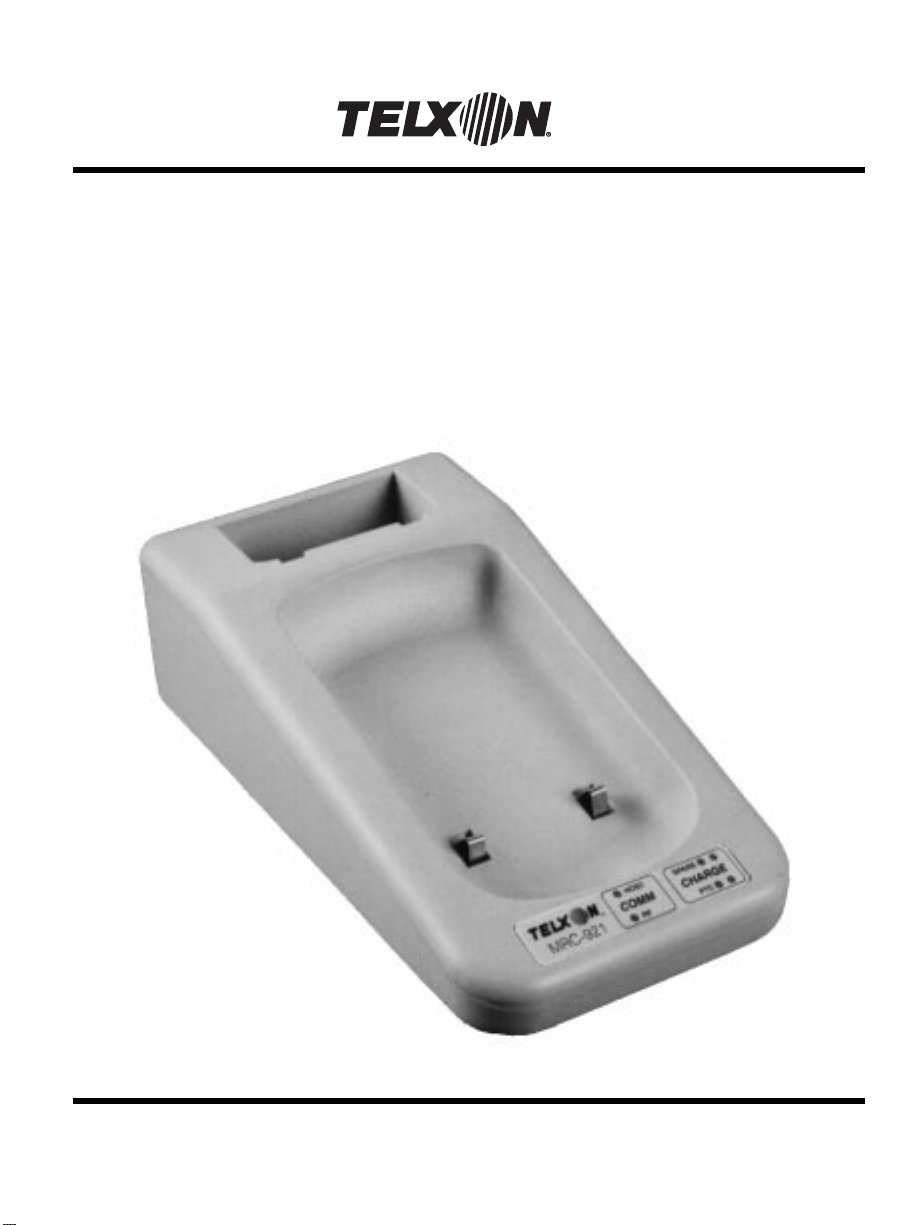
MRC-921 MircoBase
User’s Guide
Page 2

On December 1, 2000 Symbol T echnologies, Inc. completed the purchase
of Telxon Corporation. References made throughout this document to
"Telxon" or "Telxon Corporation" are be replaced with "Symbol" or
"Symbol Technologies, Inc.", respectively. Any questions, contact your
Symbol representative.
© 2000 by Symbol Technologies, Inc. All rights reserved.
No part of this publication may be reproduced or used in any form, or by any electrical or
mechanical means, without permission in writing from Symbol. This includes electronic or
mechanical means, such as photocopying, recording, or information storage and retrieval
systems. The material in this manual is subject to change without notice.
Symbol reserves the right to make changes to any software or product to improve reliability,
function, or design.
Symbol does not assume any product liability arising out of, or in connection with, the
application or use of any product, circuit, or application described herein.
No license is granted, either expressly or by implication, estoppel, or otherwise under any
Symbol Technologies, Inc., intellectual property rights. An implied license only exists for
equipment, circuits, and subsystems contained in Symbol products.
Symbol is a registered trademark of Symbol Technologies, Inc. Other product names
mentioned in this manual may be trademarks or registered trademarks of their respective
companies and are hereby acknowledged.
Symbol Technologies, Inc.
One Symbol Plaza
Holtsville, New York 11742-1300
http://www.symbol.com
Symbol Support Center: 1-800-653-5350
2
Page 3
MRC-921 MicroBase
User’s Guide
Page 4

MRC-921 MicroBase
User’s Guide
Part Number: 18467-701-01
Release Date: 4/19/95
Page 5

Telxon is a registered trademark of Telxon
Corporation.
The information contained in this manual is subject
to chang e without notice.
Telxon Corporation shall not be liable for technical or
editorial omissions or mistakes in this manual nor
shall it be liable for incidental or consequential
damages resulting from your use of the information
contained in this manual.
This manual is copyrighted. All rights are reserved.
No part of this manual may be photocopied or
reproduced in any form without the prior written
consent of Telxon.
© Copyright 1995 Telxon Corporation
All Rights Reserved.
Page 6

Contents
Regulations
. . . . . . . . . . . . . . . . . . . . . . . . . . . . . . 6
FCC statement . . . . . . . . . . . . . . . . . . . . . . . 6
FCC regulations . . . . . . . . . . . . . . . . . . . . . . . 6
DOC statement . . . . . . . . . . . . . . . . . . . . . . . 7
Safety information . . . . . . . . . . . . . . . . . . . . . . . . . . . 8
Using the radio . . . . . . . . . . . . . . . . . . . . . . . 8
Disposing of nickel-cadmium batteries . . . . . . . . . . . 9
Scope of the manual . . . . . . . . . . . . . . . . . . . . . . . . . . 10
Document conventions . . . . . . . . . . . . . . . . . . . 10
Cautions . . . . . . . . . . . . . . . . . . . . . . . . . 10
Notes . . . . . . . . . . . . . . . . . . . . . . . . . . . 10
Related publications . . . . . . . . . . . . . . . . . . . . . 10
Overview of the MRC-921 MicroBase . . . . . . . . . . . . . . . . . . . 11
Getting started . . . . . . . . . . . . . . . . . . . . . . . . . . . . 12
Unpacking the MRC-921 . . . . . . . . . . . . . . . . . . 12
Connecting the external antenna (if ordered) . . . . . . . 12
Supplying power to the MRC-921 . . . . . . . . . . . . . 13
Running the power-on self test . . . . . . . . . . . . . . . 13
Parts . . . . . . . . . . . . . . . . . . . . . . . . . . . . . . . . . 14
MicroRadio . . . . . . . . . . . . . . . . . . . . . . . . . . 14
Recharging battery packs . . . . . . . . . . . . . . . . . . . . . . . . 17
Connecting the MRC-921 to a host . . . . . . . . . . . . . . . . . . . . 19
Connecting to the host’s serial port . . . . . . . . . . . . . 19
4
Page 7

Configuring the MRC-921 . . . . . . . . . . . . . . . . . . . . . . . . 20
Communicating data
Maintaining the MRC-921
Operating conditions . . . . . . . . . . . . . . . . . . . . . 22
Handling the MRC-921 . . . . . . . . . . . . . . . . . . . 22
Storing the MRC-921 . . . . . . . . . . . . . . . . . . . . 23
Cleaning the MRC-921 . . . . . . . . . . . . . . . . . . . 23
Servicing the MRC-921 . . . . . . . . . . . . . . . . . . . 23
. . . . . . . . . . . . . . . . . . . . . . . . . . 21
. . . . . . . . . . . . . . . . . . . . . . . . 22
Troubleshooting . . . . . . . . . . . . . . . . . . . . . . . . . . . . 24
LEDs remain on after the power-on self test . . . . . . . . 24
The red LED for the PTC does not light . . . . . . . . . . 24
The red LED for the spare battery pack does not light . . 24
Both LEDs for the PTC are blinking . . . . . . . . . . . . 25
Both LEDs for the spare battery pack are blinking . . . . 25
The battery pack in the PTC or spare battery bay
takes too long to recharge . . . . . . . . . . . . . . . . . 25
The green LED for the PTC never lights . . . . . . . . . . 26
The green LED for the spare battery pack never lights . . 26
Other problems . . . . . . . . . . . . . . . . . . . . . . . 26
Appendix A . . . . . . . . . . . . . . . . . . . . . . . . . . . . . . 27
Specifications . . . . . . . . . . . . . . . . . . . . . . . . 27
Communication . . . . . . . . . . . . . . . . . . . . . 27
Electrical . . . . . . . . . . . . . . . . . . . . . . . . . 27
Environmental . . . . . . . . . . . . . . . . . . . . . . 27
Physical . . . . . . . . . . . . . . . . . . . . . . . . . 27
Radio . . . . . . . . . . . . . . . . . . . . . . . . . . . 28
Appendix B . . . . . . . . . . . . . . . . . . . . . . . . . . . . . . 29
Hardware part numbers . . . . . . . . . . . . . . . . . . . 29
Glossary . . . . . . . . . . . . . . . . . . . . . . . . . . . . . . . 30
Index . . . . . . . . . . . . . . . . . . . . . . . . . . . . . . . . . 32
5
Page 8

Regulations
FCC statement
This equipment has been tested and found to comply
with the limits for a Class A digital device, pursuant
to Part 15 of the Federal Communications
Commission (FCC) rules. These limits are designed
to provide reasonable protection against harmful
interference when the equipment is operated in a
commercial environment. This equipment generates,
uses, and can radiate radio frequency energy and, if
not installed and used in accordance with this user’s
guide, may cause harmful interference to radio
communications. Operation of this equipment in a
residential area is likely to cause harmful
interference, in which case users will be required to
correct the interference at their own expense.
The MicroRadio in the MRC-921 MicroBase
fully complies with FCC Part 15.249 limits for
intentional radiation as well as FCC Part 15.209
for unintentional emissions.
1
FCC regulations
The MRC-921 MicroBase uses radios (transceivers)
and radio communication in its operation. The
MRC-921 is a low-power transceiver operating under
FCC Part 15.249. No license is required for operation.
6
Page 9

DOC statement
This digital apparatus does not exceed the Class A
limits for radio noise emissions from digital
apparatus as outlined in the Radio Interference
Regulations of the Canadian Department of
Communications (DOC) .
The MRC-921 MicroBase’s MicroRadio is also
approved for use in Canada. No license is required for
operation.
This device complies with RSS-210 of Industry and
Science Canada. Operation is subject to the following
two conditions: (1) this device may not cause
interference, and (2) this device must accept any
interference, including interference that may cause
undesired operation of the device.
7
Page 10

Safety information
2
Using the radio
The FCC with its action in General Docket 79-144,
March 13, 1985, has adopted a safety standard
for human exposure to radio frequency (RF)
electromagnetic energy emitted by FCC regulated
equipment. Telxon subscribes to the same safety
standard for the use of its products. Proper operation
of this radio will result in user exposure substantially
below the FCC recommended limits.
Do not hold any component containing a radio such
•
that the antenna is very close to, or touching,
exposed parts of the body, especially the face or
eyes, while transmitting. Hold such a component 6
inches (15.2 centimeters) or more from your face.
Do not allow children to play with any radio
•
equipment containing a transmitter.
Do not operate a portable transmitter near
•
unshielded electrical blasting caps or in an
explosive atmosphere unless it is a type especially
qualified for such use.
Do not turn on the MRC-921 MicroBase or attempt
•
to transmit data unless the antenna is attached; if
the antenna is not attached, the radio module may
be damaged.
8
Page 11

Disposing of nickel-cadmium batteries
Nickel-cadmium batteries contain chemically active
materials that are hazardous to the environment;
therefore, they must be disp osed of properly. Never
attempt to incinerate a nickel-cadmium battery;
doing so could cause it to explode. Telxon urges you
to contact t h e En v i ro n me nt a l Pr ot ec ti o n Ag ency, the
Department of Natural Resources, a local hazardous
waste disposal agency, or the Telxon Customer
Support Center for assistance prior to disposing of
your nickel-cadmium batteries.
9
Page 12

Scope of the manual
This manual provides general information on the
MRC-921 MicroBase’s parts, features, and
accessories. It also explains how to operate and
maintain the cradle.
Document conventions
Cautions
Cautions indicate potential damage to equipment.
They are set off in the left-hand columns of this
manual by the following symbol: !.
Notes
Notes provide supplementary information. They are
set off in the left-hand columns of this manual and
are not preceded by a symbol.
3
Refer to Appendix B for a list of
manuals and their part numbers.
Related publications
The following manuals may be helpful as you operate
the MRC-921 MicroBase:
• MRC-921 Technical Reference, which contains
configuration information
• PTC-921 User’s Guide
10
Page 13

Overview of the MRC-921 MicroBase
4
Figure 1 shows a typical MRC-921
MicroBase system.
The MRC-921 can support one to five
PTCs, depending on the size and
frequency of transactions.
The MRC-921 MicroBase is a communication cradle
that allows a wireless MicroRadio-based scanner,
such as the PTC-921, to communicate with a host.
The cradle connects to the host’s serial port via cable
and communicates through an RS-232 asynchronous
protocol.
The cradle allows interactive communication between
the host and multiple PTCs. Therefore, data and
messages can be sent both to and from the host.
This unit also recharges the nickel-cadmium battery
packs that supply power for the PTC-921. Each
charger can hold a PTC-921 and a spare battery pack.
The spare battery bay contains a fast charger, which
charges spare PTC-921 battery packs in 4 hours.
The PTC bay can be ordered as either a fast or trickle
charger. A fast-charging bay charges the battery pack
in the PTC in 4 hours. A trickle-charging bay charges
the PTC’s battery pack in 12 to 16 hours.
Figure 1. A typical MRC-921 MicroBase system
PTC-921
RF
Cable
Host
MRC-921
11
Page 14

Getting started
Unpacking the MRC-921
5
Any additional accessories are
shipped in separate boxes with their
own manuals.
If anything is missing or damaged,
notify your Telxon sales
representative.
Each shipping box contains
an MRC-921 MicroBase,
•
a power pack (if ordered),
•
an external antenna (if ordered),
•
spare PTC-921 battery packs (if ordered),
•
an SC-921 and MRC-921 Instruction Sheet,
•
an MRC-921 MicroBase User’s Guide, and
•
a Guide to Maintaining NiCd Batteries.
•
1. Remove the MRC-921 from the box.
2. Remove all packing material from the MRC-921.
Save the packaging in case the cradle is ever
stored or shipped to Telxon for servi ce.
Check the contents of the package to make sure
3.
you have received everything ordered.
4. Check the MRC-921 for shipping damage.
Connecting the external antenna (if ordered)
The MRC-921 comes with an internal
antenna. An external antenna can be
added to increase coverage.
If your MRC-921 was shipped with an external
antenna, follow these instructions to connect it to the
cradle.
1. Screw the antenna onto the antenna connector on
the MRC-921’s left side.
12
Page 15

To use the unit outside of the U.S. or
Canada, you need a power pack
designed for a 220-volt AC outlet.
Supplying power to the MRC-921
Equipment re quired:
• A 12-volt, 800-mA power pack
An electrical outlet within 6 feet (1.8 meters) of
•
the MRC-921 providing 110 volts AC in the
U.S. or Canada
1. Place the MRC-921 on a flat surface in a location
where the temperature will be between 50
degrees F (10 degrees C) and 110 degrees F (43
degrees C).
Plug the power pack’s connector into the
2.
MRC-921’s power connector.
Plug the power pack into the electrical outlet.
3.
Running the power-on self test
When you plug in the MRC-921, it performs a series
of self-diagnostic tests to ensure it is operating
correctly. These tests are indicated by flashing
patterns of the PTC and spare battery pack
light-emitting diodes (LEDs).
Refer to the “Troubleshooting”
section on page 24 for information
on possible errors.
If the MRC-921 passes these diagnostics, all the
LEDs turn off after 10 seconds, provided the unit does
not contain a PTC or spare battery pack. If any LEDs
stay lit, the diagnostics have discovered an error.
13
Page 16

Parts
Figures 2 and 3 on the following pages show and
describe the external parts of the MRC-921
MicroBase. The part listed below is internal and,
therefore, is not shown in either of the figures.
MicroRadio
6
See Appendix A for radio
specifications.
This short-range radio in the MRC-921 is used to
communicate with the MicroRadio in a wireless
scanner (PTC-921).
14
Page 17

Figure 2. The MRC-921 MicroBase (front view)
1. External antenna (optional)
8. Antenna connector
2. Spare battery bay
3. PTC bay
4. Spare battery pack LEDs
1. An external antenna can be ordered to
expand the coverage of the cradle’s
MicroRadio. Coverage increases from
50 ft (15.2 m) with a standard internal
antenna to 100 ft (30.5 m) with an
external antenna.
4. These LEDs indicate the charging status of
the spare battery pack. Refer to the table
on page 18 for an explanation of the LEDs.
7. This LED glows when the MRC-921 is
communicating via its DB-9 serial port or
optional RJ-41 serial port.
7. Serial LED
2. This bay holds a PTC-921 spare battery
pack for recharging. The bay fast charges
a fully discharged spare pack in 4 hours.
5. These LEDs indicate the charging status of
the battery pack in the PTC-921. Refer to
the table on page 18 for an explanation of
the LEDs.
8. An external antenna screws onto this
connector to increase the MicroRadio’s
range.
5. PTC LEDs
6. RF LED
3. This bay holds a PTC-921 and recharges
the battery pack within it. The bay can
be ordered as a 4-hour fast charger or
as a 12- to 16-hour trickle charger.
6. This LED glows when the MRC-921 is
communicating via its MicroRadio.
15
Page 18

Figure 3. The MRC-921 MicroBase (rear view)
1. Optional RJ-41 serial port
2. DB-9 serial port
3. Power connector
4. Connect/Config button
1.This RJ-41 serial port connects the MRC-921
via cable to a host’s RS-232 serial port for
communication or configuration. Refer to
MRC-921 Technical Reference
the
configuration instructions.
4.Pressing this button upon power-up will
restore all MRC-921 configuration settings
to their default values. Refer to the
Technical Reference
information.
for configuration
for
MRC-921
2.This 9-pin serial port connects the MRC-921
via cable to a host’s RS-232 serial port for
communication or configuration. Refer to
MRC-921 Technical Reference
the
configuration instructions.
for
3.A 12-volt, 800-mA power pack plugs
into this connector to supply power to
the MRC-921.
16
Page 19

Recharging battery packs
7
!
Use the MRC-921 to recharge only
PTC-921 battery packs.
!
Recharging a cold battery pack can
damage it.
A battery pack that is not fully discharged takes less than 4 hours to
charge.
Figure 4. Recharging battery packs
Battery pack contacts
Follow the instructions in this section to use the
MRC-921 as a battery charger.
Allow any battery pack used in below-freezing
temperatures to warm up to room temperature before
recharging.
1. Insert the spare battery pack and the PTC into
their appropriate bays in the MRC-921. Insert the
spare pack so its contacts will connect with the
contacts in the spare battery bay. See Figure 4.
2. The MRC-921 automatically begins charging the
battery packs. Each bay’s red LED lights. Allow
approximately 4 hours for fast charging.
17
Page 20

If the PTC bay is a trickle charger, its
green LED will
never
light. The cradle
does not indicate a full-charge state.
If the PTC bay was ordered as a trickle charger,
the battery pack in the PTC will take 12 to 16
hours to charge.
When each bay’s green LED lights, the battery
3.
pack in that bay is charged and can be removed
and used.
Refer to the “Troubleshooting” section on page 24 for information on
possible errors.
The following table interprets the PTC and spare
battery pack LEDs.
Status condition Red LED Green LED
No battery Off Off
Charging On Off
Fully charged Off On
Error Blinking Blinking
18
Page 21

See Appendix B for a list of available
cables.
Connecting the MRC-921 to a host
The MRC-921 MicroBase can communicate with a
variety of host devices, such as personal computers
and point-of-sale (POS) terminals. Each host can
accept data from the MRC-921 through its RS-232
serial port.
Follow the instructions in this section to connect your
MRC-921 to a host.
Connecting to the host’s serial port
1. Make sure the MRC-921’s power pack is not
plugged into an electrical outlet.
2. Turn off the host to which the MRC-921 will be
connected.
Line up the 9-pin connector on the appropriate
3.
MRC-921-to-host cable with the cradle’s DB-9
serial port.
8
!
Do not force the connectors to-
gether. You could bend the pins.
Refer to page 13 for details.
or
Line up the RJ-41 connector on the appropriate
MRC-921-to-host cable with the cradle’s optional
RJ-41 serial port.
4. Gently press the two connectors together.
5. Connect the other end of the cable to the host’s
serial port.
Plug the MRC-921’s power pack into an electrical
6.
outlet.
Turn on the host to which the cradle is connected.
7.
19
Page 22

Configuring the MRC-921
Before the MRC-921 MicroBase can send data from
the wireless scanner (PTC-921) to the host, the cradle
must be properly configured for communication.
Specifically, parameters such as the radio channel,
baud rate, communication protocol, and so on need to
be selected.
9
If it has not been configured, refer
MRC-921 Technical Reference
to the
for configuration information.
Check with your supervisor to verify that your
MRC-921 has been properly configured for
communication.
20
Page 23

The default message is usually an
asterisk (*).
The data usually includes the PTC
unit ID, the data-entry type (scanned
or keyed), and the bar-code type.
Communicating data
After the MRC-921 has been connected to the host
and properly configured, communication usually
follows this general pattern:
1.All three units (PTC-921, MRC-921, and host) are
turned on.
The PTC-921 initiates communication with the
2.
MRC-921. After a successful logon, a default
message displays on the PTC’s screen.
3.Data is entered (either by being scanned or typed
with the keyboard) into the PTC-921.
The data is sent via the PTC-921’s MicroRadio to
4.
the MRC-921.
5.The MRC-921 forwards the data to the host.
10
Refer to the
Reference
may display on the PTC’s screen.
MRC-921 Technical
for a list of messages that
If the data is received successfully, an asterisk
6.
displays on the PTC-921’s screen.
If the data is not received successfully, an RF link
error displays on the PTC-921’s screen.
Communication continues with the PTC-921
7.
sending data to the host through the MRC-921.
21
Page 24

Maintaining the MRC-921
The MRC-921 is well constructed and durable;
however, it is a precision electronic device and must
be treated as such. Follow the procedures in this
section to ensure reliable service.
11
Operating conditions
The MRC-921 is designed to operate in environments
that are normally free of dust, dirt, and moisture. It
can be operated at temperatures between 50 degrees
F (10 degrees C) and 110 degrees F (43 degrees C).
Handling the MRC-921
Do not open the MRC-921. No user-serviceable
•
parts are inside.
Charge only nickel-cadmium battery packs that
•
have been designed for use in the PTC-921. Do not
recharge other types of rechargeable batteries or
any type of alkaline batteries.
Do not insert anything other than the specified
•
battery packs into the MRC-921’s spare battery bay.
If you store a battery pack in below-freezing
•
temperatures for more than 1 hour, do not charge
the battery pack until it warms up to room
temperature.
Protect the MRC-921 from excessive heat, cold,
•
moisture, and harsh, dirty env ironments.
Do not leave the MRC-921 where moisture can
•
condense on it.
22
Page 25

Storing the MRC-921
• Do not store the MRC-921 in temperatures below
20 degrees F (−29 degrees C) or above 140 degrees
−
F (60 degrees C).
• Do not store the MRC-921 in a damp or humid
environment (over 95% noncondensing).
Pack the MRC-921 in the original packing material or
in a padded box and put it in a safe place away from
dust, dirt, humidity, and excessive heat or cold.
Cleaning the MRC-921
To clean the MRC-921, slightly moisten a soft, clean,
lint-free cloth with a mild, nonabrasive cleaner and
wipe the cradle’s outside surface.
Do not use a paper towel to clean the MRC-921.
•
Do not soak the cloth used to wipe the MRC-921
•
and do not spray or pour cleaning liquids directly
onto the cradle.
If the MRC-921 becomes extremely dirty or if liquids,
dirt, or other foreign materials get inside the case,
contact your Telxon service representative.
Servicing the MRC-921
Do not service the MRC-921. Only a trained Telxon
technician may service the cradle.
23
Page 26

Troubleshooting
12
LEDs remain on after the power-on self test
Remove the spare battery pack and PTC, if
•
present, from the MRC-921. Unplug the power
pack; then plug it in again.
If the LEDs remain lit, call your Telxon service
•
representative.
The red LED for the PTC does not light
Make sure the PTC is installed correctly in its bay .
•
Exchange the battery pack in the PTC-921 with
•
the spare battery pack.
Refer to page 9 for information on
disposing of your nickel-cadmium
battery pack.
Refer to page 9 for information on
disposing of your nickel-cadmium
battery pack.
If the red PTC LED now lights, the first battery
pack is faulty and must be discarded.
If the red LED still fails to light, call your T elxon
service representative.
The red LED for the spare battery pack does not light
Make sure the battery pack is installed correctly in
•
its bay.
Exchange the spare battery pack with the battery
•
pack in the PTC-921.
If the red spare battery pack LED now lights, the
spare battery pack is faulty and must be discarded.
If the red LED still fails to light, call your T elxon
service representative.
24
Page 27

Both LEDs for the PTC are blinking
• Make sure the PTC is installed correctly in its bay.
Exchange the battery pack in the PTC-921 with the
•
spare battery pack.
Refer to page 9 for information on
disposing of your nickel-cadmium
battery pack.
Refer to page 9 for information on
disposing of your nickel-cadmium
battery pack.
If the LEDs stop blinking, the first battery pack is
faulty and must be discarded.
If both LEDs continue to blink, call your Telxon
service representative.
Both LEDs for the spare battery pack are blinking
Make sure the battery pack is installed correctly in
•
its bay.
Exchange the spare battery pack with the battery
•
pack in the PTC-921.
If the LEDs stop blinking, the spare battery pack is
faulty and must be discarded.
If both LEDs continue to blink, call your Telxon
service representative.
The battery pack in the PTC or spare battery bay takes too long to recharge
Make sure the battery pack is in serted correctly.
•
Clean the contacts on the battery pack.
•
Try another battery pack to make sure the
•
MRC-921 is working correctly.
If the battery pack still takes too long to recharge,
•
call your Telxon service representative.
25
Page 28

The green LED for the PTC never lights
If the PTC bay was ordered as a
trickle charger, the green LED will
never light. This is normal.
• Call your Telxon service representative.
The green LED for the spare battery pack never lights
• Call your Telxon service representative.
Other problems
If you experience any other problems or difficulties
with your MRC-921 MicroBase, notify your Telxon
service representative or contact the Telxon Customer
Support Center at 1-800-800-8010.
26
Page 29

Appendix
A
Specifications
Communication
Host interfaces
DB-9 serial port: Built-in one- or two-way 9-pin
RS-232 port, up to 38.4K bps
async
RJ-41 serial port: (Optional) Built-in one- or two-
way RJ-41 serial port
Electrical
Charging time
Fast charger: 4 hours
Trickle charger: 12 to 16 hours
MRC-921 input
voltage requirement: 12 VDC 800 mA
Environmental
Operating 50 to 1 1 0 deg r e es F
temperature: (10 to 43 degrees C)
Storage −20 to 140 degrees F
temperature: (−29 to 60 degrees C)
Relative humidity: 95% noncondensing
Physical
Capacity: One PTC-921 and one spare
battery pack
Length: 6.8 in/17.3 cm
Width: 5.2 in/13.2 cm
27
Page 30

Depth: 3 in/7.6 cm
W eig ht: 10.5 oz/.3 kg
Radio
Type: MicroRadio
Operating frequency: 902.5 to 927.5 MHz
Antenna: Internal (standard) or
external (optional)
Range
Internal antenna: 35 to 50 feet
(10.7 to 15.2 meters)
External antenna: 75 to 100 feet
(22.9 to 30.5 meters)
28
Page 31

Appendix
Hardware part numbers
The following table lists part numbers for ordering
the MRC-921 MicroBase and accessories.
Item Part number
MRC-921 MicroB a se 17853-001
Accessories
External antenna
Power pack
Spare PTC-921 6-volt
nickel-cadmium battery pack
Cables
MRC-921-to-host cable (9-pin)
MRC-921-to-host cable (RJ-41)
Manuals
MRC-921 Technical Reference
PTC-921 User’s Guide
Guide to Maintaining NiCd
Batteries
18634-000
10142-200
16880-001
See *
See *
19457-000
16899-000
16488-000
B
* Contact your T e lxon representative to obtain part
numbers for these cables.
29
Page 32

Glossary
asynchronous
transmission
A transmission with variable time intervals between
successive data characters. In asynchronous
communication, each data character is framed by
start and stop bits.
battery pack A sealed set of rechargeable nickel-cadmium batteries
used in the PTC-921 and recharged by the MRC-921.
bit The fundamental binary unit, either a 1 (on) or a 0
(off). In ASCII code, seven bits repr es en t o ne
character of data.
bps Bits per second. A rate of electronic data transmission.
data
communication
The transport of encoded information from one device
to another.
host computer A per sonal c omputer or mainframe that receives and
processes data from remote PTCs.
LED Light-emitting diode. The indicator lights on the
MRC-921 are of this type.
nickel-cadmium
battery
A type of rechargeable battery used in PTC-921
battery packs.
one-way
communication
The transport of information from one device
to another without interruption. In one-way
communication, the receiving device cannot respond
directly to the sending device.
RF Radio frequency.
RS-232 An Electronic Industries Association (EIA) standard
that defines the connector, connector pins, and signals
used to transfer data serially from one device to
another.
30
Page 33

signals Electronic impulses that transmit data from one
device to another.
two-way
communication
Exchange of information between two devices. After
each block of data, the receiving d evice sends a
positive or negative acknowledgment to the sendin g
device.
VDC Volts direct current. A unit of measure of electri c
potential or potential difference in a unidirectional
electrical current.
31
Page 34

Index
A
Accessories, 12
part numbers, 29
Antenna
See External antenna
See Internal antenna
B
Battery pack
See Nickel-cadmium battery pack
C
Cables, 19, 29
Capacity, 11, 27
Charge time, 11, 15, 17-18, 27
Charging the nickel-cadmium battery
pack, 11, 17-18
time required, 11, 15, 17-18, 27
Cleaning the MRC-921, 23
Communication, 11, 21
specifications, 27
Configuration settings
restoring, 16
Configuring the MRC-921, 16, 20
Connect/Config button, 16
Connecting the MRC-921 to a host, 19
Customer Support Center
contacting, 26
D
Data
communicating, 21
DB-9 serial port, 15-16
DOC statement, 7
Document conventions
cautions, 10
notes, 10
E
Electrical specifications, 27
Environmental specifications, 27
External antenna, 15
connecting, 12
range, 15, 28
F
Fast charger, 11, 15, 17, 27
FCC regulations, 6
FCC statement, 6
H
Handling the MRC-921, 22
Hardware part numbers, 29
Host, 11, 19, 21
I
Internal antenna, 12
range, 15, 28
32
Page 35

L
N
LEDs
interpretation table, 18
PTC, 13, 15, 24-26
remain on after power-on self test, 24
RF, 15
Serial, 15
spare battery pack, 13, 15, 24-26
M
Maintaining the MRC-921, 22-23
Manuals
part numbers, 29
Messages, 11, 21
MicroRadio, 14-15
specifications, 28
MRC-921 MicroBase
capacity, 11, 27
cleaning, 23
configuring, 16, 20
connecting to a host, 19
handling, 22
maintaining, 22-23
operating temperature, 13, 22, 27
overview, 11
parts, 14-16
powering, 13
servicing, 23
specifications, 27-28
storage temperature, 23, 27
storing, 23
unpacking, 12
MRC-921 MicroBase system, 11
Nickel-cadmium battery pack
disposing of, 9
recharging, 11, 17-18
takes too long to recharge, 25
O
Operating conditions, 22
Operating temperature, 13, 22, 27
Overview of the MRC-921 MicroBase,
11
P
Packing material
saving, 12
Part numbers, 29
Parts of the MRC-921, 14-16
Physical specifications, 27-28
Power connector, 16
Powering the MRC-921, 13
Power-on self test
running, 13
Power pack, 16
specifications, 13
Protocol, 11
PTC-921, 11, 15
inserting into the MRC-921, 17
removing from the MRC-921, 18
PTC bay, 15
PTC LEDs, 13, 15
blinking, 25
green LED never lights, 26
interpretation table, 18
red LED does not light, 24
Publications, 10
33
Page 36

R
T
Radio
safety information, 8
specifications, 28
Recharging battery packs, 17-18
Regulations
DOC statement, 7
FCC regulations, 6
FCC statement, 6
Related publications, 10
RF LED, 15
RF link error, 21
RJ-41 serial port, 16, 19
S
Safety information, 8-9
Scope of the manual, 10
Serial LED, 15
Serial port, 11, 15, 16, 19
connecting to, 19
Servicing the MRC-921, 23
Shipping damage, 12
Spare battery bay, 15
Spare battery pack
inserting into the MRC-921, 17
removing from the MRC-921, 18
Spare battery pack LEDs, 13, 15
blinking, 25
green LED never lights, 26
interpretation table, 18
red LED does not light, 24
Specifications
communication, 27
electrical, 27
environmental, 27
physical, 27-28
radio, 28
Storage temperature, 23, 27
Storing the MRC-921, 23
Temperature
operating, 13, 22, 27
storage, 23, 27
Trickle charger, 11, 15, 18, 27
Troubleshooting, 24-26
U
Unpacking the MRC-921, 12
34
Page 37

Telxon Corporation/3330 West Market Street, Akron, Ohio 44334/216-867-3700/800-800-8001
Part No. 18467-701-01 Printed in U.S.A.
 Loading...