

Page 1

Spectrum24
Access Point AP-3020
Product Reference Guide
PRE-RELEASE
70-20504-02
April 1999
www.symbol.com
Page 2

Copyright
Copyright © 1999 by Symbol Technologies, Inc. All rights reserved.
No part of this publication may be modified or adapted in any way, for any purposes without permission in writing from Symbol. The material in this manual
is subject to change without notice.
Symbol reserves the right to make changes to any product to improve reliability, function, or design.
No license is granted, either expressly or by implication, estoppel, or otherwise under any Symbol Technologies, Inc., intellectual property rights. An implied
license only exists for equipment, circuits, and subsystems contained in Symbol products.
Symbol, the Symbol logo and Spectrum24 are registered trademarks of Symbol Technologies, Inc.
Other product names mentioned in this manual may be trademarks or registered trademarks of their respective companies and are hereby acknowledged.
Novell and LAN Workplace are registered trademarks of Novell Inc.
Patents
This product is covered by one or more of the following U.S. and foreign Patents:
U.S. Patent No.4,360,798; 4,369,361; 4,387,297; 4,460,120; 4,496,831; 4,593,186; 4,603,262; 4,607,156; 4,652,750; 4,673,805; 4,736,095;
4,758,717; 4,816,660; 4,845,350; 4,896,026; 4,897,532; 4,923,281; 4,933,538; 4,992,717; 5,015,833; 5,017,765; 5,021,641; 5,029,183;
5,047,617; 5,103,461; 5,113,445; 5,130,520 5,140,144; 5,142,550; 5,149,950; 5,157,687; 5,168,148; 5,168,149; 5,180,904; 5,229,591;
5,230,088; 5,235,167; 5,243,655; 5,247,162; 5,250,791; 5,250,792; 5,262,627; 5,262,628; 5,266,787; 5,278,398; 5,280,162; 5,280,163;
5,280,164; 5,280,498; 5,304,786; 5,304,788; 5,306,900; 5,321,246; 5,324,924; 5,337,361; 5,367,151; 5,373,148; 5,378,882; 5,396,053;
5,396,055; 5,399,846; 5,408,081; 5,410,139; 5,410,140; 5,412,198; 5,418,812; 5,420,411; 5,436,440; 5,444,231; 5,449,891; 5,449,893;
5,468,949; 5,471,042; 5,478,998; 5,479,000; 5,479,002; 5,479,441; 5,504,322; 5,519,577; 5,528,621; 5,532,469; 5,543,610; 5,545,889;
5,552,592; 5,578,810; 5,581,070; 5,589,679; 5,589,680; 5,608,202; 5,612,531; 5,619,028; 5,664,229; 5,668,803; 5,675,139; 5,693,929;
5,698,835; 5,705,800; 5,714,746; 5,723,851; 5,734,152; 5,734,153; 5,745,794; 5,754,587; 5,658,383; D305,885; D341,584; D344,501;
D359,483; D362,453; D362,435; D363,700; D363,918; D370,478; D383,124; D391,250.
Invention No. 55,358; 62,539; 69,060; 69,187 (Taiwan); No. 1,601,796; 1,907,875; 1,955,269 (Japan).
European Patent 367,299; 414,281; 367,300; 367,298; UK 2,072,832; France 81/03938; Italy 1,138,713.
Symbol Technologies, Inc.
One Symbol Plaza
Telephone:(800)SCAN234, (516)738-2400, TLX:6711519
Holtsville, N.Y. 11742-1300
www.symbol.com
ii Spectrum24 Access Point AP-3020 Product Reference Guide
Page 3

About This Document
This document covers...and has the following sections:
• ...
• ...
• ...
Reference Documents
This reference guide refers to the following documents:
Part Number Document Title
70-xxxxx-01 Title
RFCs (Request For Comments) can be found on the Web at: http://www.ctrl-c.lin.se/ftp/DOC/RFC.
Conventions
Keystrokes are indicated as follows:
ENTER identifies a key.
FUNC, CTRL, C identifies a key sequence. Press and release each key in turn.
Press A+B press the indicated keys simultaneously.
Hold A+B press and hold the indicated keys while performing or waiting for another
function. Used in combination with another keystroke.
Typeface conventions used include.
<angles> indicates mandatory parameters in a given syntax.
[brackets] for command line, indicates available parameters; in configuration files
brackets act as separators for options.
GUI Screen text indicates the name of a control in a GUI-based application.
Italics indicates the first time a term is used, a book title, variables, and menu titles.
Spectrum24 Access Point AP-3020 Product Reference Guide iii
Page 4

Screen
indicates monitor screen dialog. Also indicates user input. A screen is
the hardware device on which data appears. A display is data arranged
on a screen.
Terminal indicates text shown on a radio terminal screen.
This document uses the following for certain conditions or types of information:
Indicates tips or special requirements.
Indicates conditions that can cause equipment damage or data loss.
Indicates a potentially dangerous condition or procedure that only Symboltrained personnel should attempt to correct or perform.
iv Spectrum24 Access Point AP-3020 Product Reference Guide
Page 5

Contents
Chapter 1 Introduction............................................................................................1
1.1 Ethernet Access Point (AP) ............................................................... 1
1.1.1 New Features ...................................................................... 3
1.2 Radio Basics .................................................................................. 3
1.2.1 S24 Network Topology......................................................... 4
1.2.2 Quick Wireless AP Setup ...................................................... 8
1.2.3 Cellular Coverage ............................................................... 9
1.2.4 Site Topography ................................................................ 12
1.3 Advanced Radio Theory................................................................ 12
1.3.1 MAC Layer Bridging........................................................... 13
1.3.2 Auto Fallback to Wireless Mode.......................................... 15
1.3.3 DHCP Support................................................................... 15
1.3.4 Media Types......................................................................16
1.3.5 Bridging Support................................................................17
1.3.6 Frequency Hopping Spread Spectrum ................................. 21
1.3.7 MU Association Process...................................................... 23
1.3.8 Mobile IP (Roaming Across Routers) ................................... 26
1.3.9 Supporting CAM and PSP Stations.......................................28
1.3.10 Data Encryption...............................................................29
1.3.11 HTTP, HTML Web Server Support...................................... 30
1.3.12 Management Options ......................................................31
Chapter 2 Configuring the AP............................................................................. 35
2.1 Gaining Access to the UI .............................................................. 35
2.1.1 Using Telnet ......................................................................35
2.1.2 Using a Direct Serial Connection ........................................ 36
2.1.3 Using a Dial-Up Connection .............................................. 38
2.1.4 Using a Web Browser.........................................................38
2.2 Navigating the UI......................................................................... 45
Spectrum24 Access Point AP-3020 Product Reference Guide v
Page 6

2.2.1 Entering Admin Mode ........................................................... 47
2.2.2 Changing the Access to the UI ...............................................48
2.2.3 Configuring for Dial-Up to the UI .......................................... 49
2.2.4 Navigating the UI Via a Web Browser .................................... 50
2.3 Access Point Installation...................................................................51
2.4 Configuring System Parameters .......................................................53
2.5 Configuring Radio Parameters .........................................................58
2.5.1 Wireless Operation Parameters..............................................63
2.6 Configuring PPP .............................................................................. 67
2.6.1 PPP Direct............................................................................. 67
2.6.2 Establishing Connection ........................................................ 68
2.6.3 PPP with Modems.................................................................. 68
2.6.4 Originating AP...................................................................... 68
2.6.5 Answering AP ....................................................................... 69
2.6.6 Initiating Modem Connection.................................................70
2.7 Configuring the SNMP Agent ...........................................................70
2.8 Configuring the ACL........................................................................74
2.8.1 Range of MUs....................................................................... 74
2.8.2 Adding Allowed MUs.............................................................76
2.8.3 Removing Allowed MUs......................................................... 76
2.8.4 Enable/Disable the ACL ........................................................ 77
2.8.5 Removing All Allowed MUs.................................................... 77
2.8.6 Load ACL from MU List .........................................................77
2.9 Configuring Address Filtering........................................................... 78
2.9.1 Adding Disallowed MUs ........................................................ 79
2.9.2 Removing Disallowed MUs .................................................... 79
2.10 Configuring Type Filtering ............................................................. 79
2.10.1 Adding Filter Types ............................................................. 79
2.10.2 Removing Filter Types.......................................................... 79
2.10.3 Controlling Type Filters........................................................80
2.11 Clearing MUs from the AP ............................................................. 80
vi Spectrum24 Access Point AP-3020 Product Reference Guide
Page 7

2.12 Setting Logging Options ................................................................80
2.13 Manually Updating AP Firmware.................................................... 82
2.13.1 Updating using TFTP...........................................................82
2.13.2 Updating using Xmodem..................................................... 85
2.14 Auto Upgrade all APs Via Messaging.............................................. 88
2.15 Performing Pings........................................................................... 90
2.16 Mobile IP Using MD5 Authentication .............................................. 94
2.17 Saving the Configuration ...............................................................95
2.18 Resetting the AP ............................................................................ 96
2.19 Restoring Configuration................................................................. 96
Chapter 3 Monitoring Statistics...........................................................................97
3.1 System Summary............................................................................. 97
3.2 Interface Statistics.......................................................................... 100
3.3 Forwarding Counts........................................................................ 102
3.4 Mobile Units ................................................................................. 102
3.5 Mobile IP ......................................................................................107
3.6 Known APs.................................................................................... 108
3.7 Ethernet Statistics........................................................................... 110
3.8 Radio Statistics ..............................................................................112
3.9 Miscellaneous Statistics..................................................................120
3.9.1 Analyzing Frequency Use .................................................... 122
3.9.2 Analyzing Retries................................................................. 123
3.10 Event History...............................................................................124
3.11 Clearing Statistics........................................................................ 125
Chapter 4 Hardware Installation ...................................................................... 127
4.1 Precautions................................................................................... 127
4.2 Package Contents ......................................................................... 127
4.3 Requirements................................................................................ 128
4.3.1 Network Connection ........................................................... 128
4.3.2 10Base-T UTP..................................................................... 129
4.3.3 Single Cell.......................................................................... 129
Spectrum24 Access Point AP-3020 Product Reference Guide vii
Page 8

4.4 Attaching the Antenna(s)................................................................130
4.4.1 Antenna Extension Cables ................................................... 131
4.5 Power Options ..............................................................................131
4.6 Mounting the AP ...........................................................................132
4.7 Connecting the Power Adapter.......................................................132
4.8 LED Indicators............................................................................... 133
4.8.1 WLAP mode LED display. .................................................... 134
4.9 Troubleshooting ............................................................................ 136
4.9.1 Ensure wired network is operating........................................136
4.10 Setting Up MUs...........................................................................138
Appendix A Specifications..................................................................................A - 1
A.1 Physical Characteristics.................................................................A - 1
A.2 Radio Characteristics....................................................................A - 2
A.3 Network Characteristics................................................................A - 3
Appendix B Supported Modems....................................................................... B - 1
Appendix C Customer Support........................................................................ C - 1
Appendix D Regulatory Compliance .............................................................. D - 1
viii Spectrum24 Access Point AP-3020 Product Reference Guide
Page 9

Chapter 1 Introduction
Spectrum24 is a frequency-hopping, spread spectrum cellular network that
operates between 2.4 and 2.5 GHz (gigahertz). This technology provides
a high-capacity network using multiple access points within large or
small environments.
Spectrum24 features include:
• bridging architecture to provide communication between radio and
wired multiple network segments
• a design based on the IEEE 802.11 standard
• a 2 Mbps data rate for fast operation
• seamless roaming for mobile users with devices such as laptop
computers, wireless PCs, scanning terminals and computer devices with
PCMCIA slots.
1.1 Ethernet Access Point (AP)
The Ethernet Access Point (AP) provides a bridge between Ethernet wired
LANs and Spectrum24 wireless networks. It provides transparent access
between Ethernet wired networks and radio-equipped mobile units (MUs).
MUs include the full line of Symbol Spectrum24 terminals, scanners, thirdparty devices and other devices.
The AP provides 1 and 2 Mbps data transfer rate on the radio network.
It monitors Ethernet traffic and forwards appropriate Ethernet messages to
MUs over the Spectrum24 network. It also monitors MU radio traffic and
forwards MU packets to the Ethernet LAN.
The AP meets the following:
• the regulatory requirements for Europe and many other areas of
the world
• FCC part 15, class A with no external shielding
• FCC part 15 class B, ETS 300-339 compliance, including CE mark.
Spectrum24 Access Point AP-3020 Product Reference Guide 1
Page 10

Introduction
The AP has the following features:
• built-in diagnostics including a power-up self-check
• a four-way bridging architecture (wireless, Ethernet, PPP, internal stack)
• wireless MAC interface
• 10baseT Ethernet port interface with full-speed filtering
• 100 mW and 500 mW radio versions
• power supply IEC connector and a country-specific AC power cable
• PC/AT Serial Port Interface
• built-in antenna diversity
• multiple antenna options
• support for 127 mobile units
• SNMP support
• wireless AP support
• repeater functions.
An MU communicating with an AP appears on the network as a peer to
other network devices. The wireless interface is transparent. The AP receives
data from its wired or wireless interfaces and forwards the data to the
proper interface.
The AP has connections for the wired network, external antennas and
power supply. The AP attaches to a wall or ceiling depending on installationsite requirements.
The AP requires a single antenna for radio transmission and reception.
The dual-antenna system allows the AP to select the best radio signal.
2 Spectrum24 Access Point AP-3020 Product Reference Guide
Page 11

1.1.1 New Features
• IEEE 802.1d Spanning Tree Support
• Auto-Fallback to Wireless Mode
• Increased MIB support
• DHCP Support
• HTTP, Web server Support
• Mobile IP Support
• Programmable SNMP Trap Support using SNMP Agents
• Data Encryption
• Wireless Options in Radio Parameters
• ACL (Access Control List)
• AP Auto Upgrade of other APs via messaging
• Multiple Gateways.
1.2 Radio Basics
Spectrum24 uses electromagnetic waves, radio signals, to transmit and
receive electric signals without wires. Users communicate with the network by
establishing radio links between terminals and APs.
Introduction
Spectrum24 uses FM (frequency modulation) to transmit digital data from
one device to another. Using FM, a radio signal begins with a carrier signal
that provides the base or center frequency. The digital data signal is
superimposed on the carrier signal (modulation). The radio signal
propagates into the air as electromagnetic waves. A receiving antenna in the
path of the waves absorbs the waves as electrical signals. The receiving
device demodulates the signal by removing the carrier signal. This
demodulation results in the original digital data.
Spectrum24 uses the environment (the air and certain objects) as the
transmission medium. Spectrum24 radio devices use the 2.4 to 2.5-GHz
frequency range, a license-free range throughout much of the world. The
actual range is country-dependent.
Spectrum24 Access Point AP-3020 Product Reference Guide 3
Page 12

Introduction
Spectrum24 devices, like other Ethernet devices, have unique, hardwareencoded Media Access Control (MAC) or IEEE addresses. MAC addresses
determine the device sending or receiving data. The MAC address is a 48-bit
number written as six hexadecimal bytes separated by colons. For example:
00:A0:F8:24:9A:C8
To locate the AP MAC address see the bottom of the unit.
1.2.1 S24 Network Topology
The variations possible in Spectrum24 network topologies depend on the
following factors:
• the AP function in the network
• a 1 or 2 Mbps data transfer rate
•the wireless AP (WLAP) interface.
A WLAP communicates only with its root AP through the wireless interface as
discussed in The Root AP and Association Process on page 14.
4 Spectrum24 Access Point AP-3020 Product Reference Guide
Page 13

Introduction
If the AP is not in wireless mode, select from the following topologies:
• A single AP used without the wired network provides a single-cell wireless
network for peer-to-peer MUs.
• A single AP can bridge the Ethernet and radio networks.
• Multiple APs can coexist as separate, individual networks at the same site
without interference using different Net_IDs.
Spectrum24 Access Point AP-3020 Product Reference Guide 5
Page 14
Introduction
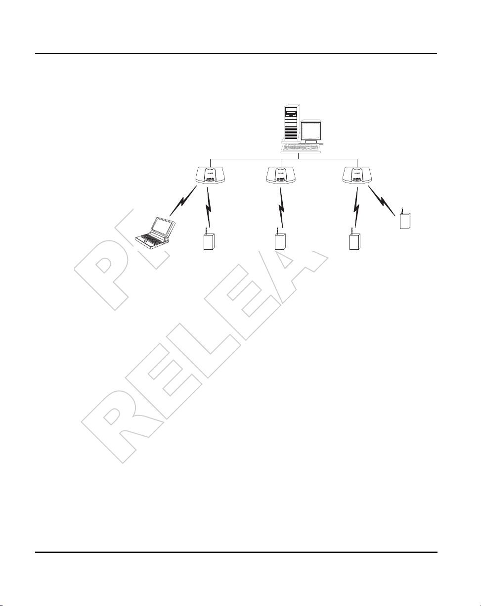
• Multiple APs wired together provide a network with better coverage area
and performance.
• Multiple 1 Mbps and 2 Mbps APs wired together.
6 Spectrum24 Access Point AP-3020 Product Reference Guide
Page 15

In WLAP mode, a wireless AP-to-AP connection functions:
• as a bridge to connect two Ethernet networks
Introduction
• as a repeater to extend coverage area without additional
network cabling
Spectrum24 Access Point AP-3020 Product Reference Guide 7
Page 16

Introduction
When using a wireless AP-to-AP connection, use the optimal antenna
configuration for the site. For example, use a directional antenna when
establishing a dedicated wireless bridge or repeater.
• A wireless AP network is possible, depending on the network bandwidth
and configuration. Each wireless AP can have connections with up to
four other wireless APs.
Using more than two WLAPs to establish a connection slows network
performance for all topologies. If not using the AP Auto Configure feature,
disable WNMP Functions and AP-AP State Xchg parameters under the Set
System Configuration screen to increase WLAP performance.
WNMP is a Wireless Network Management Protocol.
1.2.2 Quick Wireless AP Setup
To set up an AP for wireless operation automatically, select the Enabled
option for the WLAP Mode parameter. To set these values, See 2.5
Configuring Radio Parameters on page 43.
The WLAP initialization process length depends on the time specified in the
WLAP Forward Delay field. See 2.5 Configuring Radio Parameters on page
43.
8 Spectrum24 Access Point AP-3020 Product Reference Guide
Page 17

1.2.3 Cellular Coverage
The AP establishes an average communication range with MUs called a
Basic Service Set (BSS) or cell. When in a particular cell the MU associates
and communicates with the AP of that cell. Each cell has a Basic Service Set
Identifier (BSS_ID). In 802.11, the AP MAC address represents the BSS_ID.
The MU recognizes the AP it associates with using the BSS_ID. Adding APs to
a LAN establishes more cells in an environment, making it an RF Network
using the same Net_ID or Extended Service Set (ESS).
Introduction
APs with the same Net_ID (ESS) define the coverage area. The MU searches
for APs with a matching Net_ID (ESS) and synchronizes with an AP to
establish communications. This allows MUs within the coverage area to move
about or roam. As the MU roams from cell to cell, it switches APs. The switch
occurs when the MU analyzes the reception quality at a location and decides
the AP to communicate with based on the best signal strength and lowest MU
load distribution.
If the MU does not find an AP with a workable signal, it performs a scan to
find any AP. As MUs switch APs, the AP updates the association table.
Roaming is transparent in high-level applications.
Spectrum24 Access Point AP-3020 Product Reference Guide 9
Page 18

Introduction
The user can configure the Net_ID (ESS). A valid Net_ID (ESS) is an
alphanumeric, case-sensitive identifier up to 32 characters. Ensure all nodes
within one LAN use the same Net_ID (ESS) to communicate on the same
LAN. Multiple wireless LANs can coexist in a single environment by assigning
different Net_IDs (ESS) for APs.
The Root AP and Association Process
By default, APs with WLAP Mode enabled and within range of each other
automatically associate and configure wireless operation parameters at
power up. This association process determines the wireless connection
viability and establishes the Root AP and subsequently designated WLAPs.
APs communicating wirelessly together require the same Net_ID (ESS) setting.
The root AP maintains the wireless connection among WLAPs by sending out
beacons, sending and receiving configuration BPDU (Bridge Protocol Data
Unit) packets between each designated WLAP. The WLAP with the lowest
WLAP ID becomes the Root AP. The WLAP ID is a concatenation of the WLAP
Priority value and the MAC address. Ensure the WLAPs associated with the
Root AP use the Root AP hop sequence, DTIM (Delivery Traffic Indicator
Maps) and TIM (Traffic Indicator Message) interval.
10 Spectrum24 Access Point AP-3020 Product Reference Guide
Page 19

Introduction
In this configuration, the WLAP Priority value is the default 8000 Hex. On
concatenating this value to the MAC addresses of the APs, AP A on Ethernet I
has the lowest WLAP ID with 800000A0F800181A, making it the Root AP. AP
C uses the AP A hop sequence, DTIM and TIM interval.
If AP D on Ethernet II has data for a device on Ethernet I, it requires a bridge
or a repeater. In this configuration, AP C functions as a repeater. To ensure
transmission to devices on Ethernet I, AP D has to use the AP A hop
sequence, DTIM and TIM interval.
To prevent forming a loop, disable WLAP mode on B and E. See 2.5
Configuring Radio Parameters on page 43.
To manually designate AP B as the Root AP, assign it a lower WLAP Priority
value. See 2.5 Configuring Radio Parameters on page 43. Assigning a WLAP
Priority value of 7000 Hex to the AP B MAC address of
00:A0:F8:11:23:5D causes AP B to become the Root AP by having the
lowest WLAP ID of 700000A0F811235D.
802.1d Spanning Tree Support
This protocol creates a loop-free topography with exactly ONE path between
every LAN. This is the shortest path from the Root AP to each AP and LAN. If
an AP or LAN fails, a new route is calculated and added to the tree. All
packet forwarding follows the spanning tree. APs have to choose one AP as
the Root AP. The same holds true for WLAPs associating with the root AP or
another AP connected to the Ethernet LAN to prevent forming loops.
Spectrum24 Access Point AP-3020 Product Reference Guide 11
Page 20

Introduction
1.2.4 Site Topography
For optimal performance, locate MUs and APs away from transformers,
heavy-duty motors, fluorescent lights, microwave ovens, refrigerators and
other industrial equipment.
Signal loss can occur when metal, concrete, walls or floors block
transmission. Locate antennas in open areas or add APs as needed to
improve coverage.
In an open-air environment the radio range is up to 2000 ft. (606 m). In a
typical office or retail environment the radio range is between 180 and 250
ft (54.5 to 75.7 m).
Site Surveys
A site survey analyzes the installation environment and provides users with
recommendations for the equipment and its placement.
1.3 Advanced Radio Theory
To improve AP management and performance, users need to understand
basic AP functionality and configuration options. The AP includes features for
different interface connections and network management.
The AP provides MAC layer bridging between its interfaces. The AP monitors
traffic from its interfaces and, based on frame address, forwards the frames
to the proper destination. The AP tracks the frames sources and destinations
to provide intelligent bridging as MUs roam or network topologies change.
The AP also handles broadcast and multicast message initiations and
responds to MU association requests.
12 Spectrum24 Access Point AP-3020 Product Reference Guide
Page 21

1.3.1 MAC Layer Bridging
The AP listens to all packets on all interfaces and builds an address database
using the unique IEEE 48-bit address (MAC address). An address in the
database includes the interface media that the device uses to associates with
the AP. The AP uses the database to forward packets from one interface to
another as they arrive. The bridge forwards packets addressed to unknown
systems to the Default Interface (either Ethernet or PPP). Users can use the
Ethernet interface as a wireless AP interface.
Users have up to four wireless AP interfaces available for the bridging
algorithm (v3.10 and above only).
Introduction
The AP internal stack interface handles all messages directed to the AP.
Spectrum24 Access Point AP-3020 Product Reference Guide 13
Page 22

Introduction
Each AP stores information on destinations and their interfaces to facilitate
forwarding. When a user sends an ARP (Address Resolution Protocol) request
packet, the AP forwards it over all enabled interfaces (Ethernet, PPP, radio
and WLAP) except over the interface the ARP request packet was received.
On receiving the ARP response packet, the AP database keeps a record of
the destination address along with the receiving interface. With this
information, the AP forwards any directed packet to the correct destination.
The AP forwards packets for unknown destinations to the Ethernet interface.
Only ARP request packets received over radio are echoed-back over radio
for other APs to hear.
The AP removes from its database destinations or interfaces not used for a
specified time. The AP refreshes its database when it transmits or receives
data from these destinations and interfaces.
Filtering and Access Control
The AP provides facilities to limit the MUs that associate with it and the data
packets that can forward through it. Filters can provide network security or
improve performance by eliminating broadcast/multicast packets from the
radio network.
The ACL (Access Control List) contains the MAC addresses for MUs allowed
to associate with the AP. This provides security by preventing unauthorized
access.
The AP supports using a disallowed address list of destinations. This feature
prevents the AP from communicating with specified destinations. This can
include network devices that do not require communication with the AP or
its MUs.
14 Spectrum24 Access Point AP-3020 Product Reference Guide
Page 23

Depending on the setting, the AP can keep a list of frame types that it
forwards or discards when they reach it. The Type Filtering option prevents
specific frames (indicated by the 16-bit DIX Ethernet Type field) from being
processed by the AP. These include certain broadcast frames from devices
unimportant to the wireless LAN but take up bandwidth. Filtering out
unnecessary frames can also improve performance.
1.3.2 Auto Fallback to Wireless Mode
The AP supports an Auto Fallback to Wireless when the hardware Ethernet
connection fails or becomes broken. The AP resets itself and during
initialization attempts to associate with any other WLAP in the network. This
feature is available only if the WLAP Mode is enabled and the Ethernet
Timeout parameter is set to one. See Configuring System Parameters on
page 39 and Wireless Operation Parameters on page 46.
1.3.3 DHCP Support
The AP uses Dynamic Host Configuration Protocol (DHCP) to obtain a leased
IP address and network configuration information from a remote server.
DHCP is based on BOOTP protocol. DHCP can coexist or interoperate with
BOOTP. An AP sends out a DHCP request searching for a DHCP server to
acquire the network configuration and firmware filenames. Because BOOTP
and DHCP are interoperable, whichever responds first becomes the server
allocating the information. The DHCP client automatically sends a DHCP
request every XX hours/days to renew the IP address lease as long as the AP
is running. (This parameter is programmed at the DHCP server. Example:
Windows NT servers typically are set for 3 days.) The AP can optionally
download two files when a boot takes place, the firmware file and an HTML
file, because firmware versions 4.00-31 and above support Web servers.
Users can program the DHCP or BOOTP server to transfer these two files
when a DHCP request is made.
Introduction
When the AP receives a network configuration change or not able to renew
the IP address lease the AP sends out an SNMP trap.
Spectrum24 Access Point AP-3020 Product Reference Guide 15
Page 24

Introduction
1.3.4 Media Types
The AP supports bridging between Ethernet, radio and serial media.
The Ethernet interface fully complies with Ethernet Rev. 2 and IEEE 802.3
specifications. The AP supports 10Base-T wired connections and full-speed
filtering. The data transfer rate over radio waves is 1 or 2 Mbps. This rate
requires adjustment of AP application time-out values for data transfer
between the Ethernet and radio interfaces. The Ethernet interface is optional
for single-cell or PPP-connected networks.
The radio interface conforms to IEEE 802.11 specification. The interface
operates at 1 and 2 Mbps using frequency hopping, spread spectrum radio
technology. The AP supports multiple-cell operations with fast, transparent
roaming between cells. With the frequency-hopping system, each cell
operates independently. Each cell provides a 1 or 2 Mbps bandwidth. Adding
cells to the network provides increased coverage area and total system
capacity. The AP supports MUs operating in Power Save Polling (PSP) mode
or Continuously Aware Mode (CAM) without user intervention.
The DB-9, 9-pin, RS-232 serial port provides a UI (User Interface) or a PPP
(Point to Point Protocol) connection. The UI provides basic management tools
for the AP. The PPP provides a link between APs using a serial connection. The
serial link supports short haul (direct serial) or long haul (telephone-line)
connections. The AP is a DTE (Data Terminal Equipment) device with male
pin connectors for the RS-232 port. Connecting the AP to a PC requires a
null modem cable and connecting the AP to a modem requires a straightthrough cable.
16 Spectrum24 Access Point AP-3020 Product Reference Guide
Page 25

1.3.5 Bridging Support
The AP PPP (Point to Point Protocol) interface, accessible from the serial port
at the rear of the AP, provides two types of bridging operations:
• Data-link bridging between two APs. A network using a data-link bridge
provides radio coverage by using a remote AP in a location
geographically distant from the AP connected to the Ethernet network.
The remote AP cannot provide an Ethernet connection to other APs. MUs
associating with the remote AP transmit and receive from the Ethernet
network via the PPP link.
Introduction
Spectrum24 Access Point AP-3020 Product Reference Guide 17
Page 26

Introduction
• Internet Protocol bridging between an AP and a computer. To establish
an Internet Protocol bridge with an AP, ensure the computer includes the
appropriate Telnet software with PPP and TCP/IP protocols. By using
Telnet, a computer at a remote location can connect to any AP on an
Ethernet network, as long as data transfers through IP packets.
A PPP link provides the option of using a direct serial link or modem to
extend wired Ethernet topologies.
Once in PPP mode, the AP automatically attempts to communicate with
the other device using the Data-Link Bridging (DLB) protocol. An AP using
DLB communicates on the MAC level, and receives and transmits
Ethernet frames.
If the other device does not support DLB, the AP attempts to communicate
using Internet Protocol Control Protocol (IPCP). An AP using IPCP
communicates on the IP level, and receives and transmits IP (Internet
Protocol) packets.
18 Spectrum24 Access Point AP-3020 Product Reference Guide
Page 27

Introduction
The PPP implementation in the AP uses the Link Control Protocol (LCP) and
Network Control Protocol (NCP) as described in:
• RFC 1171: the Point-to-Point Protocol, July 1990
• RFC 1220: PPP Extensions for Bridging, April 1991
• RFC 1332: The PPP Internet Protocol Control Protocol, May 1992
• RFC 1661: The Point-to-Point Protocol, July 1994.
RFCs are Requests For Comments used in Internet Communities.
The AP database dynamically tracks MUs and APs on the PPP interface.
Packets forward to the PPP link after the AP determines their destination.
The PPP implementation in the AP uses the NCP as described in RFC 1220:
PPP Extensions for Bridging to encapsulate packets at the Ethernet level. The
PPP provides IP bridging control as defined by RFC 1172 and MAC-level
bridging. It provides support for PPP negotiations conforming to RFC 1661.
Users cannot plug a non-AP node directly into the AP serial port, only AP-toAP PPP links.
Refer to RFC 1171: The Point to Point Protocol and RFC 1220: PPP Extensions
for Bridging for information.
Spectrum24 Access Point AP-3020 Product Reference Guide 19
Page 28

Introduction
PPP Connection
Connecting two APs with a direct serial link requires a null-modem
serial cable.
Connecting two APs with modem devices requires straight-through cables
between the APs and modems. Using modems requires using a telephone
line for as long as the link remains active.
If using a modem connection, one AP represents the originating AP and the
other represents the answering AP. When using a PPP link, do not use the
serial port to access the UI. Access to the UI requires establishing a Telnet
session with the AP.
20 Spectrum24 Access Point AP-3020 Product Reference Guide
Page 29

1.3.6 Frequency Hopping Spread Spectrum
The Spread spectrum technique (also known as broadband) takes a
narrowband signal and spreads the data signal over a broad segment of the
radio frequency band or spectrum. Spectrum24 uses the Frequency Hopping
Spread Spectrum (FHSS) technology for radio communication. FHSS spreads
the signal by transmitting a short burst on one frequency, jumping to another
frequency for another short burst and so on. Spectrum24 uses the 2.4 - 2.5
GHz range depending on the country, this range does not require licensing
from the FCC. FHSS offers a higher transmission rate than a conventional
radio narrowband method.
In FHSS systems, the carrier frequency of the transmitter changes (or hops) in
accordance with the pseudo-random code sequence. The code sequence
dictates the frequency order selected by the transmitter. The transmitter takes
the input data and spreads it in a predefined method. Each receiver has to
understand this predefined method and reconstruct the signal before
interpreting data. Stations in a cell using FHSS techniques hop or change the
carrier frequency at synchronized intervals. Government regulatory agencies
and standards, such as ETSI, MKK, the FCC and IEEE 802.11, determine the
number of frequency hops (79 for the U.S.), the hopping pattern (sequence
each frequency is used) and dwell time (time at each frequency). The FCC
requires 75 or more hopping frequencies used and a maximum of 400ms
for dwell time per frequency. The transmitter and receiver synchronize to the
Introduction
Spectrum24 Access Point AP-3020 Product Reference Guide 21
Page 30

Introduction
hop sequence to ensure communication. The time synchronization field
included in message packets coordinates the hop timing of all units. The user
can program the length each hop lasts. Each hop is a frequency at least
6 MHz away from the previous frequency and has a 1 MHz bandwidth.
FHSS can survive in an adverse environment and coexist with other devices/
services in the same band. The average signal strength being relatively low
on any given frequency is a result of FHSS. When the signal intelligence is
spread out over several MHz in the frequency spectrum, the resulting power
spectrum also spreads out (less than 1 watt). This results in the transmitted
power spread out over a wide frequency bandwidth and makes detection
very difficult (without the code sequence).
Hopping provides enhanced data reception in the presence of interfering
signals, like fixed frequency radio networks or microwave ovens. The system
also resists interference because it spends a short time on each given
frequency. If an interfering source is present (interference at a specific
frequency), only a small number of frequency hops are blocked instead of
the entire range. With
interference occurring on one frequency, the data is
retransmitted on a subsequent hop at another frequency. Even if constant
22 Spectrum24 Access Point AP-3020 Product Reference Guide
Page 31

interference exists on a given frequency, it affects the radio network for only a
short time on that specific frequency. Although APs can share the same
hopping sequence, they usually do not synchronize in time. Rarely do they
simultaneously arrive at the same frequency, referred to as contention.
Interfering signals can reduce overall throughput at some frequencies. This
reduces the probability and impact of overlapping frequencies or collisions.
Although devices can hop to the same frequency, they eventually hop to
different frequencies after the hop time.
With Spectrum24, each AP on the local network negotiates a different
hopping sequence at start-up. This allows APs to provide frequency
separation and evenly divide the frequency spectrum among the units.
1.3.7 MU Association Process
APs recognize MUs through an association method. The AP keeps a list of
MUs it services. MUs associate with the AP based on the following conditions:
• the signal strength between the AP and MU
• the MUs currently associated with the AP
• the MU Supported Rate.
Introduction
Mobile Unit Access Point (Rate Set)
transmit rate
(supported rates)
111NANA
1 & 2 default 1 Dynamic Rate
2NANANA2
Spectrum24 Access Point AP-3020 Product Reference Guide 23
1 only 1 reqd, 2 optl
default
Control
1 & 2 reqd 2 only
Dynamic Rate
Control
2
Page 32

Introduction
Where:
reqd = required
optl = optional
NA = No Association
Dynamic Rate Control= rate chosen for best transmission.
MUs perform preemptive roaming by intermittently scanning for APs and
associating with the best available AP. Before roaming and associating with
APs, MUs perform full or partial scans to collect AP frequency-hopping
statistics like:
• hopping sequences
• the current hopping frequencies
• the time until the end of the hop (hop interval).
Scanning is a periodic process where the MU sends out probe messages on
all frequencies defined by the country code. The statistics enable an MU to
reassociate by synchronizing its frequency to the AP. The MU continues
communicating with that AP until it needs to switch cells or roam.
MUs perform full scans at start-up. In a full scan, an MU uses a sequential set
of channels as the scan range. For each channel in range, the MU tests for
CCA (Clear Channel Assessment). When a transmission-free channel
becomes available, the MU broadcasts a probe with the Net_ID and the
broadcast BSS_ID. An AP-directed probe response generates an MU ACK
(Mobile Unit Acknowledgment) and the addition of the AP to the AP table
with a proximity classification. An unsuccessful AP packet transmission
generates another MU probe on the same channel. If the MU fails to receive
a probe response within the time limits, it repeats the probe process on the
next channel in the sequence. This process continues through all channels in
the range.
MUs perform partial scans at programmed intervals, when missing expected
beacons or after excessive transmission retries. In a partial scan, the MU
scans APs classified as proximate on the AP table. For each channel, the MU
tests for CCA. The MU broadcasts a probe with the Net_ID and broadcast
BSS_ID when the channel is transmission-free. It sends an ACK to a directed
24 Spectrum24 Access Point AP-3020 Product Reference Guide
Page 33

Introduction
probe response from the AP, and updates the AP table. An unsuccessful AP
packet transmission causes the MU to broadcast another probe on the same
channel. The MU classifies an AP as out-of-range in the AP table if it fails to
receive a probe response within the time limits. This process continues
through all APs classified as proximate on the AP table.
An MU can roam within the coverage area by switching APs. Roaming is
transparent and virtually instantaneous in high-level applications. Roaming
occurs when:
• an unassociated MU attempts to associate or reassociate with an
available AP
• the supported rate changes or the MU finds a better transmit rate with
another AP
•the RSSI (received signal strength indicator) of a potential AP exceeds the
current AP
• the ratio of good-transmitted packets to attempted-transmitted packets
falls below a threshold
• the MU detects an imbalance in the number of MUs associated with
available APs and roams to a less loaded AP.
The MU selects the best available AP and adjusts itself to the correct hopping
sequence to begin association. After establishing an association between the
AP and MU, the AP begins forwarding any frames it receives addressed to the
MU. Each frame from the AP contains fields for the current hop frequency
and how much time remains in the current hop sequence. The MU uses these
fields to resynchronize its hopping to the AP.
Spectrum24 Access Point AP-3020 Product Reference Guide 25
Page 34

Introduction
1.3.8 Mobile IP (Roaming Across Routers)
The Internet Protocol identifies the MU point of attachment to a network
through its IP address. The AP routes packets for the MU according to the
location information contained in the IP header. If the MU roams across
routers to another subnet, the following situations occur:
• The MU changes its point of attachment without changing its IP address
and this causes forthcoming packets to become undeliverable.
• The MU changes its IP address when it moves to a new network and this
causes it to lose the connection.
Mobile IP enables an MU to communicate with other hosts using
only its home IP address after changing its point-of-attachment to the
internet/intranet.
Conceptually, Mobile IP is like giving an individuals local post office a
forwarding address when leaving home for an extended period. When mail
arrives for the individuals home address it is forwarded by the local post
office to the individuals current care-of-address. Using this method, only the
local post office requires notification of the individuals current address
instead of each correspondent. While the example given represents the
general concept of Mobile IP operation and functionality it does not represent
the implementation of Mobile IP used.
A tunnel is the path taken by the original packet encapsulated within the
payload portion of a second packet to some destination on the network.
A Home Agent is an AP acting as a router on the MUs home network.
The home agent intercepts packets sent to the MUs home address and
tunnels the message to the MU at its current location. This happens as long
as the MU keeps its home agent informed of its current location on some
foreign link.
A Foreign Agent is an AP acting as a router at the MUs location on a foreign
link. The foreign agent de-tunnels packets for the MU sent by the MUs home
agent. The foreign agent also serves as the default router for packets sent out
by the MU connected on the same foreign link.
26 Spectrum24 Access Point AP-3020 Product Reference Guide
Page 35

Introduction
A care-of-address is the IP address used by the MU visiting a foreign link.
This address changes each time the MU moves to another foreign link. It can
also be viewed as an exit point of a tunnel between the MUs home agent and
the MU itself.
The S24 Mobile IP (roaming across routers) feature enables an MU on the
Internet to move from one subnet to another while keeping its IP address
unchanged.
To configure this feature, See 2.4 Configuring System Parameters on page
39.
The scanning and associating process continues for active MUs. This allows
the MUs to find new APs and discard out-of-range or deactivated APs. By
always testing the airwaves, the MUs can choose the best network connection
available.
The following diagram illustrates Mobile IP (roaming across routers):
Set the MU for mobile IP as specified in the MUs user documentation.
Spectrum24 Access Point AP-3020 Product Reference Guide 27
Page 36

Introduction
Security has become a concern to mobile users. Enabling the Mobile-Home
MD5 key option in the System Configuration menu generates a 16-byte
checksum authenticator using an MD5 algorithm. The MU and AP share the
checksum, called a key, to authenticate transmitted messages between them.
The AP and MU share the key while the MU is visiting a foreign subnet. The
MU and AP have to use the same key. If not, the AP refuses to become the
Home Agent for the MU. The maximum key length is 13 characters. The AP
allows all printable characters.
1.3.9 Supporting CAM and PSP Stations
CAM (Continuously Aware Mode) stations leave their radios on continuously
and hear every beacon and message transmitted. These systems operate
without any adjustments by the AP.
A beacon is a uniframe system packet broadcast by the AP to keep the
network synchronized. A beacon includes the Net_ID (ESS), the AP address,
the Broadcast destination addresses, a time stamp, a DTIM (Delivery Traffic
Indicator Maps) and the TIM (Traffic Indicator Message).
PSP (Power Save Polling) stations power off their radios for long periods.
When an MU in PSP mode associates with an AP, it notifies the AP of its
activity status. The AP responds by buffering packets received for the MU. The
PSP-mode MU wakes up to listen to the AP beacon every n
where
n is a PSP-mode value from the 1 to 10-range; the Beacon Interval is
set on the MU. When the MU wakes up and sees its bit set in the TIM, it issues
a poll request to the AP for packets stored for it. The AP sends them to the
MU and the MU goes back to sleep. A DTIM field, also called a countdown
field, informs MUs of the next window for listening to broadcast and multicast
messages. The AP sends the messages following the
the DTIM interval defined in the AP. When the AP has buffered broadcast or
multicast messages for associated MUs, it sends the next DTIM with a DTIM
Interval value. This value decreases by ’1’ with each successive beacon. The
AP sends broadcast and multicast messages immediately following the
beacon where the DTIM value is ’0.’ To prevent a PSP-mode MU from
sleeping through a DTIM notification, select a PSP mode value less than or
equal to the DTIM value. PSP-mode MUs hear the beacons and awaken to
receive the broadcast and multicast messages.
th
Beacon Interval
nth beacon where n is
28 Spectrum24 Access Point AP-3020 Product Reference Guide
Page 37

A TIM is a compressed virtual bitmap identifying the AP associated MUs in
PSP mode that have buffered directed messages. MUs issue a poll request
when APs issue a TIM. A beacon with the broadcast-indicator bit set causes
the MU to note DTIM Count field value. The value informs the MU of the
beacons remaining before next DTIM. This ensures the MU turns on the
receiver for the DTIM and the following BC/MC packet transmissions.
1.3.10 Data Encryption
Mobile nodes and other hosts on any network face possible information
theft. This occurs when an unauthorized user eavesdrops on someone else to
glean information. The absence of a physical connection makes wireless
links particularly vulnerable to this form of theft. Encryption becomes the
most efficient method in preventing information theft and improving data
security. Encryption requires scrambling and coding of information, typically
with mathematical formulas called algorithms, before the information is
transmitted over a communications link or network. An algorithm is a set of
instructions or formula for scrambling the data. A key is the specific code
used by the algorithm to encrypt or decrypt the data. Decryption is the
decoding and unscrambling of the received encrypted data. The same
device, host computer or front-end processor, usually performs both
encryption and decryption. The data transmit or receive direction determines
whether the encryption or decryption function is performed. This device takes
the plain text and scrambles or encrypts it and transmits the data over the
network, typically by mathematically combining the key with the plain text as
prescribed by the algorithm. At the receiving end another device takes the
encrypted text and decrypts, unscrambles, the text resulting in the original
plain text. An authorized user can know the algorithm, but cannot interpret
the encrypted data without the appropriate key. Only the sender and receiver
of the transmitted data know the secret key. Symbol uses the Wired
Equivalent Privacy (WEP) algorithm, specified in IEEE 802.11 section 8, for
encryption and decryption. WEP uses the same secret key for both encrypting
and decrypting plain text. Typically an external key management service
distributes the secret key. Users should change the key often for added
security. IEEE 802.11 defines two types of authentication, Open System and
Shared Key. Open system authentication is a null authentication algorithm.
Shared key authentication is an algorithm where both the AP and the MU
Introduction
Spectrum24 Access Point AP-3020 Product Reference Guide 29
Page 38

Introduction
share an authentication key to perform a checksum on the original message.
By default, IEEE 802.11 devices operate in an open system network where
any wireless device can associate with an AP without authorization. A wireless
device with a valid shared key is allowed to associate with the AP.
Authentication management messages (packets) are unicast, meaning
authentication messages transmit from one AP to one MU only, not
broadcast or multicast.
1.3.11 HTTP, HTML Web Server Support
The native language of the Web is Hypertext Transfer Protocol (HTTP). The
protocol makes requests from browsers (the user) to servers and responses
from servers to browsers. This function provides the user with a web-based
format for configuration and firmware download capabilities. Web pages
are written in HTML (Hypertext Markup Language.) HTML allows the user to
create web pages containing text, graphics and pointers or links to other web
pages or elsewhere on the page or document. Pointers are generally known
as Uniform Resource Locators (URLs). A URL is essentially the name of the
web page. There are three parts to the URL:
• the protocol (sometimes called a scheme)
• the DNS (Domain Name Server) the machine where the page is located
• the local name that identifies the page (usually the filename).
The HTML language describes how to format the document. Much like a
copyeditor describes which fonts to use, such as the location, color, header
size and text.
30 Spectrum24 Access Point AP-3020 Product Reference Guide
Page 39

1.3.12 Management Options
Managing Spectrum24 includes viewing network statistics and setting
configuration options. Statistics track network activity of associated MUs and
data transfers on the AP interfaces. Configuration involves setting system
operating parameters and filters used in bridging.
Introduction
The AP requires one of the following to perform a custom installation or
maintain the Spectrum24 network:
• SNMP (Simple Network Management Protocol)
• wired or wireless LAN workstation with a Telnet client
• terminal or PC with RS-232 connection and ANSI emulation
Changing one AP does not affect the configuration of other APs on the
network. Make configuration changes to APs individually. Each AP requires
an individual IP address.
Spectrum24 Access Point AP-3020 Product Reference Guide 31
Page 40

Introduction
Programmable SNMP Trap Support
The SNMP protocol defines the method for obtaining information about the
networks operating characteristics, changing parameters for routers and
gateways, and consists of three elements:
• management stations
• management information
• a management protocol (MIB).
Nodes can be hosts, routers, bridges or other devices that can communicate
status information. An SNMP Agent is a node that runs the SNMP
management process to systematically monitor and manage the network.
The management station performs network management by running
application management software.
An SNMP trap is an alert to all configured management stations of some
significant event that occurred on the network. The management station
queries all stations for the details of each specific event, including what,
when, where the event took place and the current status of the node or
network. The format or structure is defined in the SNMP protocol. The MIB
defines what and who monitors the variables.
Using SNMP
The AP includes SNMP agent versions accessible via an SNMP manager
application such as, HP Open View or Cabletron Spectrum MIB browser. The
SNMP agent supports SNMP versions 1 and 2, MIB II, the 802.11 MIB and
one Symbol proprietary Symbol MIB (Management Information Base). The
SNMP agent supports read-write, read-only or disabled modes. The AP
supports traps that return to the SNMP manager when certain events occur.
The Wireless LAN Installation and Utilities disk packaged with MUs contains
the MIB.
Increased MIB Support
The MIB (Management Information Base) defines what the management
station needs to understand and which objects the station manages. The MIB
has ten categories defined with approximately 175 variables.
32 Spectrum24 Access Point AP-3020 Product Reference Guide
Page 41

Introduction
Using the UI
The UI (User Interface) is a text-based maintenance tool integrated into the
AP. It provides statistical displays, AP configuration options and firmware
upgrades. Access to the UI requires one of the following:
Telnet Client Gain access to the AP built-in Telnet server from any AP
interface including remote Ethernet connections. See Using
Telnet on page 29.
Direct Serial
Connection
Dial Up Access The dial-up access method requires a communication
SNMP Via a MIB
Browser
Web Browser Gain access to the AP built-in Web server from any AP
Acts as a DTE device to connect directly to a DTE device with
a null-modem serial cable. The direct serial access method
requires a communication program with ANSI emulation.
See Using a Direct Serial Connection on page 30.
program with ANSI emulation on the remote terminal or
PC. The terminal or PC dials to an AP with a modem
connection. The AP supports connection to a Hayescompatible 28,800-baud or faster modem. See Using a
Dial-Up Connection on page 31.
Gain access to the AP SNMP function via a MIB Browser.
Typically a Network Manager uses this feature, Symbol does
not recommend AP access using this interface method.
Refer to the MIB Browser documentation for usage.
interface including remote Ethernet connections. See Using
a Web Browser on page 33.
Spectrum24 Access Point AP-3020 Product Reference Guide 33
Page 42

Introduction
34 Spectrum24 Access Point AP-3020 Product Reference Guide
Page 43

Chapter 2 Configuring the AP
Software configuration requires setting up a connection to the AP and
gaining access to the UI (User Interface).
The dot in front of certain parameters, functions or options ( .Antenna Selection
Primary Only
(ESS) when choosing the Save ALL APs-[F2] option.
) indicates these items are updated to all APs with the same Net_ID
2.1 Gaining Access to the UI
Setting up access to the UI depends on the connection used. Select the setup
that best fits the network environment. If using a PPP connection, access the
UI through a Telnet session.
2.1.1 Using Telnet
Using a Telnet session to gain access to the UI requires a remote station to
have a TCP/IP stack. The remote station can be on the wired or wireless LAN.
To access the AP from the workstation:
1. From the DOS prompt Telnet to the AP using its IP address:
Telnet xxx.xxx.xxx.xxx
2. At the prompt enter the password:
Symbol
The password is case-sensitive.
Spectrum24 Access Point AP-3020 Product Reference Guide 35
Page 44

Configuring the AP
3. Press the ESC key. The AP displays the Main Menu:
Symbol Access Point MAIN MENU
Show System Summary AP Installation
Show Interface Statistics Special Functions
Show Forwarding Counts Set System Configuration
Show Mobile Units Set RF Configuration
Show Known APs Set Serial Port Configuration
Show Ethernet Statistics Set Access Control List
Show RF Statistics Set Address Filtering
Show Misc. Statistics Set Type Filtering
Show Event History Set SNMP Configuration
Enter Admin Mode Set Event Logging Configuration
– If the session is idle (e.g. no input) for the configured time, the
session terminates.
– To manually terminate the session, press CTRL+D.
Set the System Password in the Set System Configuration screen.
2.1.2 Using a Direct Serial Connection
The AP serial port is a DB-9, 9-pin male connector. The serial port allows PPP
connections to another AP, or a UI connection to a configuration PC.
Connecting the AP directly to a PC with a 9-pin serial port requires a null
modem cable with the following configuration:
36 Spectrum24 Access Point AP-3020 Product Reference Guide
Page 45

Configuring the AP
The factory-configured AP accepts a direct serial connection to the UI.
Configure the AP for the following:
Enable serial port.
•
•Set Port Use to
Disable modem connection.
•
UI.
Configure these settings in the Set Serial Port Configuration screen within the
UI. See Configuring for Dial-Up to the UI on page 36.
Assuming the UI and serial port are enabled on the AP:
1. Attach a null modem serial cable from the AP to the terminal or PC
serial port.
2. From the terminal, start the communication program.
3. Select the correct COM port along with the following parameters.
emulation ANSI
baud rate 19200 bps
data bits 8
stop bits 1
parity none
flow control none
There is no password requirement.
4. Press ESC to refresh the display. The AP displays the Main Menu.
5. Exit the communication program to end the session.
Spectrum24 Access Point AP-3020 Product Reference Guide 37
Page 46

Configuring the AP
2.1.3 Using a Dial-Up Connection
The AP supports a dial-up connection to the UI. This requires accessing the
UI from Telnet or a direct serial connection and changing the serial port
configuration. Configure the AP for the following:
Enable serial port.
•
• Set serial port for
Disable any modem connection.
•
• Set AP to
answer mode.
UI.
Configure these settings in the Set Serial Port Configuration screen within the
UI. See Configuring for Dial-Up to the UI on page 36.
2.1.4 Using a Web Browser
Using a Web Browser to gain access to the UI requires the workstation to
have a TCP/IP stack and access to a Web browser. The remote station can be
on the wired or wireless LAN.
To use this feature the Web Browser, such as Internet Explorer 4.0 and higher
or Netscape, requires JavaScript.
To insure the
Web Server option is enabled:
1. Access the UI using a Serial or Telnet connection.
2. Select the System Configuration screen.
3. Verify the
Web Server option on the System Configuration screen
is enabled.
4. Save the configuration by selecting
Save-[F1].
Reset the AP for changes to take effect.
1. Select the Special Finctions screen.
2. Select
3. At the comfirmation prompt, select
38 Spectrum24 Access Point AP-3020 Product Reference Guide
Reset AP.
Yes.
Page 47

To enable help file access change the Help URL parameter:
1. Select the Special Functions screen.
Configuring the AP
2. Select the
Alter Filename(s)/HELP URL/TFTP Server/DHCP by pressing the e
key.
3. Press ENTER.
4. Use the DOWN ARROW key to select the
.HELP URL option.
5. Type the IP address/URL (Universal Request Locator) or the directory/
folder of the Web server for the Help file location.
6. Press ENTER.
7. Use the DOWN ARROW key to select
8. Save the new setting by selecting the
OK-[CR] and press ENTER.
Save Configuration option.
9. At the comfirmation prompt, select Yes.
10. The Main Menu screen is displayed.
Reset the AP for changes to take effect.
1. Select the Special Finctions screen.
2. Select
3. At the comfirmation prompt, select
Reset AP.
Yes.
Setup Web Server Help File Access
A Web server is required to access the help file from the Spectrum24 Access
Point Configuration Management System web pages. To access the help file
from a Web server create a directory/folder on the server disk for the help file
to reside. Copy the *.gif and *.htm files to this direstory/folder.
This prcedure is for Network or System Administration personnel only.
Spectrum24 Access Point AP-3020 Product Reference Guide 39
Page 48

Configuring the AP
This installation process is for Windows NT 4.0.
1. From the desktop windows Task Bar select Start.
2. From the pulldown menu select Programs.
3. From this menu select Microsoft Internet Server.
4. From this menu select Internet Service Manger.
5. The Internet Service Manager window is displayed.
6. Note: insure <servername> (ntserver_170) www is running.
7. Select Properties
8. Select Service Properties
9. The www Service Properties for <servername> windows opens.
10. Select the Directories Tab.
11. Select the Add button.
12. The Directory Properties window opens.
13. Type the Directory/Floder path as indicated.
14. Select the Virtual Directory button.
15. Type the folder alias and select OK.
16. Enable the Defalut document button.
17. Type S24apHelp.htm and select apply.
18. Select OK to exit the window.
19. Start the Web browser.
40 Spectrum24 Access Point AP-3020 Product Reference Guide
Page 49

Configuring the AP
20. Enter the IP Address for the associated AP to access the AP via the
Web browser.
21. To access help from any Spectrum24 Access Point Configuration
Management System web page select the Help button always located in
the right frames top right corner on each page.
Setup Local Workstation Help File Access
To access the help file from a local workstation the Help file needs to be
loaded on the hard disk.
To install the Help file run the InstallShield program.
1. From the floppy disk or Symbol Web site, http://www.symbol.com/ , click
on the file UAPHTMLHelp_Install.exe Icon.
2. The Unpacking UAP HTML Help window appears indicating the file is
unpacking and the installation help program is preparing to start.
Spectrum24 Access Point AP-3020 Product Reference Guide 41
Page 50

Configuring the AP
3. The UAP HTML Help Installation Setup screen is displayed.
4. Follow the on-screen instructions to install the Help file on the local
workstation hard disk.
To access the Help file located on the local workstation:
1. From the Windows Task bar click the Start button.
2. From the Start pulldown menu click Programs
3. From the Programs pulldown menu click Symbol Technologies or the
directory name chosen during the install process.
4. Click UAP HTML Help to launch the help file program.
To exit the Help file:
1. From the window menu bar click File.
2. From the pulldown menu click Close/Exit.
Accessing Web Browser UI
To access the AP UI via a Web Browser from a workstation:
1. From the NCPA properties window set the IP address of the workstation
and the subnet mask. The system tells the user to reboot for property
changes to take effect.
The workstation, in this case, is the workstation or laptop using the Web
browser to access the UI.
2. To verify the connection, ping the AP. At the default DOS prompt, type:
Ping -t xxx.xxx.xxx.xxx
– If the ping receives no response, verify that the hardware
connections, IP address, gateway address and subnet mask are
correct. If correct, contact the site System Administrator for
network assistance.
42 Spectrum24 Access Point AP-3020 Product Reference Guide
Page 51

Configuring the AP
3. Type the AP IP address in the Address field of a Web browser such as
Internet Explorer 4.0 and higher or Netscape.
http://xxx.xxx.xxx.xxx
The Main Page for the Spectrum24 Access Point Configuration Management
System displays:
The Web pages look different than the Telnet, Direct Serial or Dial-Up
Connections. Access the different pages using the nodes located in the left
frame. Refer to the online help file for Web page navigation, page contents
and parameter use.
4. For access to the Easy Setup and Configuration pages this popup
dialogue box appears:
Spectrum24 Access Point AP-3020 Product Reference Guide 43
Page 52

Configuring the AP
5. Enter the AP name.
Symbol Access Point
6. Enter the password:
Symbol
The AP name and password are case-sensitive.
To manually terminate the session, exit the browser.
To view configuration, function, option changes on the Web page(s) turn off
the caching function for the browser used. If this property/option is not
turned off the browser returns the previous view of the page without the
changes. To insure the latest version of a web page is viewed set this option
in the browser. For Netscape from the menu bar select Edit, Properties,
Advanced, Cache. Document in cache is compared to document on
network: Every time. For Internet Explorer form the menu bar select View,
Internet Options, Temporary Internet files, Settings. Check for newer
versions of stored pages: Every visit to the page.
Set the System Password under the Configuration folder, on the Security
page.
44 Spectrum24 Access Point AP-3020 Product Reference Guide
Page 53

2.2 1DYLJDWLQJWKH8,
The AP displays a Main Menu when gaining access to the UI:
Symbol Access Point MAIN MENU
Show System Summary AP Installation
Show Interface Statistics Special Functions
Show Forwarding Counts Set System Configuration
Show Mobile Units Set RF Configuration
Show Known APs Set Serial Port Configuration
Show Ethernet Statistics Set Access Control List
Show RF Statistics Set Address Filtering
Show Misc. Statistics Set Type Filtering
Show Event History Set SNMP Configuration
Enter Admin Mode Set Event Logging Configuration
The top line displays the System Name for the AP (default is Symbol Access
Point) and the name of the configuration screen.
The UI uses the following keystrokes to navigate through the menus and
screens depending on the terminal emulation. For terminal emulation
programs that do not support using arrow keys or function keys, use the
control-character equivalents:
UP ARROW CTRL + O
DOWN ARROW CTRL + I
LEFT ARROW CTRL + U
RIGHT ARROW CTRL + P
F1 CTRL + Q
F2 CTRL + W
F3 CTRL + E
F4 CTRL + R
Configuring the AP
Spectrum24 Access Point AP-3020 Product Reference Guide 45
Page 54

Configuring the AP
The following conventions also apply when navigating through screens
and menus:
• To select menu items, press the key corresponding to the bold letter for
the item (case-sensitive hot key). Press ENTER to select the item.
• Press TAB to scroll through menu items.
• To change menu items, note the bottom line on the screen for
configuration options. For multiple choice options, press the bold letter to
select. To change values, type in the value and press ENTER. If the value
is invalid, the AP beeps and restores the original value. Press TAB to
scroll to next menu item.
• The bottom line on the menu enables menu/screen changes to take
effect. Press TAB to scroll to the item and press ENTER to select.
• When changing values such as System Name or System Password, accept
values by scrolling to the next field or pressing ENTER.
• Some screens use function keys to initiate commands. For example,
• Statistic screens include
refresh (F1) and Timed (F2) commands to
update the display.
• Some options listed at the bottom of screens indicate possible
commands for a selected item. For example, in the Known APs screen,
highlighting an AP on the list and pressing F1 brings up the Ping function
to Ping that AP.
• To exit from submenus, press ESC.
46 Spectrum24 Access Point AP-3020 Product Reference Guide
Page 55

Administration screens include options for saving or clearing data that
appear on the bottom line of the screen. Confirmation prompts include the
following:
OK Registers settings but does not save them in NVM
(nonvolatile memory). A reset command returns to
previously saved settings.
Save Saves all settings (including ones not on that screen) to
NVM. This is the same as Save Configuration in the Special
Functions screen.
Save ALL APs To save the AP installation configuration information to all
APs with the same Net_ID
configuration changes for the current AP on the Known APs
table to update their configuration and reset after the
configuration has been modified.
Cancel Does not register settings changed in a screen.
2.2.1 Entering Admin Mode
The UI defaults to User mode that allows read-only access to the APs
functions (e.g., view statistics). Switching to Admin mode provides access to
configuration menus and allows the user to configure the AP.
Configuring the AP
. This option saves the
Entering Admin mode requires the administration password.
1. Select Enter Admin Mode from the Main Menu. The AP prompts for the
administration password:
Enter System Password:
2. Enter the default password:
Symbol
The password is case sensitive.
Spectrum24 Access Point AP-3020 Product Reference Guide 47
Page 56

Configuring the AP
– If the password is correct, the AP displays the Main Menu with the
Enter Admin Mode menu item changed to Exit Admin Mode.
– If the password is incorrect, the AP continues to display the Main
Menu with the Enter Admin Mode menu item.
Set the System password in the Set System Configuration screen.
2.2.2 Changing the Access to the UI
To prevent unauthorized Telnet access, change the configuration access to
the UI. This includes enabling or disabling the Telnet Logins or changing the
System Password.
To change Telnet access to the AP:
1. Select Set System Configuration from the Main Menu.
2. Select Telnet Logins.
3. Press the SPACE BAR or LEFT/RIGHT-ARROW keys to toggle between
Enabled and Disabled.
4. Use the TAB key to highlight the SAVE-[F1] function at the bottom of the
screen, press ENTER to confirm save.
To change the System Password:
1. Select Set System Configuration from the Main Menu.
2. Press TAB to select System Password.
3. Type in the new password and press ENTER.
4. Use the TAB key to highlight the SAVE-[F1] function at the bottom of the
screen, press ENTER to confirm save.
48 Spectrum24 Access Point AP-3020 Product Reference Guide
Page 57

2.2.3 Configuring for Dial-Up to the UI
A dial-up connection to gain access to the UI requires a straight-through
cable between the modem and the AP. The remote PC requires a modem and
a communication program (e.g. Microsoft Windows Terminal program).
See Appendix B: Supported Modems for modems supported by the AP.
Configuring Serial Port
To enable and configure the serial port connection on the AP:
1. Select Set Serial Port Configuration from the Main Menu.
Configuring the AP
2. Set the Port Use parameter to
3. Set the Modem Connected parameter to
PPP.
Yes.
Configure the other settings as required on the AP.
Answer Wait Time The time waiting for a remote connection before dropping
the attempt. The default is
60 seconds from a 5 to 255-
second range.
Modem Speaker AP sends a command to the modem to turn on/off the
modem speaker. The default is
On.
Inactivity Timeout The inactivity time on the UI that causes the AP to
terminate the connection while using a modem. The
default is
5 minutes from a 0 to 255-minute range. The 0
value indicates no timeout.
Spectrum24 Access Point AP-3020 Product Reference Guide 49
Page 58

Configuring the AP
Configuring the Dial-Up System
Assuming the PPP, serial port and answer mode are enabled on the AP:
1. Attach the straight-through serial cable from the AP to the modem.
2. Verify modem connects to the telephone line and has power. Refer to
modem documentation.
3. From the remote terminal, start the communication program.
4. Select the correct serial port along with the following parameters.
emulation ANSI
baud rate 19200 bps
data bits 8
stop bits 1
parity none
flow control none
5. Dial out to the AP with the correct telephone number.
No password required.
6. Press ESC to refresh the display. The AP displays the Main Menu.
Hanging Up
To hang up from the UI while connected:
1. Select the Special Functions Menu from the Main Menu.
2. Select Modem Hangup.
2.2.4 Navigating the UI Via a Web Browser
Refer to the online help file for the Web Browser navigation methods and
basic functionality.
50 Spectrum24 Access Point AP-3020 Product Reference Guide
Page 59

2.3 $FFHVV3RLQW,QVWDOODWLRQ
The AP UI includes an AP Installation screen supporting additional
configuration to set basic parameters for a Spectrum24 network. These
parameters include designating a gateway address that provides the ability
to forward messages across routers on the wired Ethernet.
To install an AP:
1. Enter Admin Mode.
2. Select AP Installation from the Main Menu to display:
Symbol Access Point
Access Point Installation
Unit Name Symbol Access Point .Additional Gateways
IP Address 157.235.96.52 0.0.0.0
0.0.0.0
.Gateway IP Address 157.235.96.2 0.0.0.0
0.0.0.0
.Subnet Mask 255.255.255.0 0.0.0.0
0.0.0.0
.Net_ID (ESS) 101 0.0.0.0
Configuring the AP
.Antenna Selection Primary Only
OK-[CR] Save-[F1] Save ALL APs-[F2] Cancel-[ESC]
Where:
Unit Name the AP name
IP Address the network-assigned Internet Protocol address
of the AP
Gateway IP Address IP address of a router the AP uses on the
Ethernet default gateway
Spectrum24 Access Point AP-3020 Product Reference Guide 51
Page 60

Configuring the AP
Subnet Mask The first two or three sets of numbers in the four
sets of numbers making up the IP address of any
device on a network represents the subnet mask
values. The first two sets of numbers specify the
network domain, the next set specifies the subset
of hosts within a larger network and the final set
specifies an individual computer. These values
help divide a network into sub networks and
simplify routing and data transmission.
Net_ID (ESS) the unique 32-character, alphanumeric, case-
sensitive network identifier of the AP
Antenna Selection enables selection of antenna diversity
Additional Gateways The IP address of the additional gateways used.
Access up to eight gateways.
3. Verify the values set reflect the network environment. Change them
as needed.
4. In the Antenna Selection field, use SPACE BAR or LEFT/RIGHT-ARROW
keys to toggle between
Primary Only and Primary and Secondary.
5. To register settings select
Save displays a confirmation prompt.
OK or Save to write changes to NVM. Selecting
6. To save the AP installation configuration information to all APs with
the same Net_ID select
Save ALL APs-[F2]. This option saves
the configuration changes for the current AP on the Known APs table
to update their configuration and reset after the configuration has
been modified.
7. To disregard any changes made to this screen and return to the previous
menu, select
52 Spectrum24 Access Point AP-3020 Product Reference Guide
Cancel-[ESC].
Page 61

2.4 &RQILJXULQJ6\VWHP3DUDPHWHUV
The AP provides configuration options for how the unit operates
including security access and interface control. Some parameters do not
require modification.
1. Select Set System Configuration from the Main Menu to display:
Symbol Access Point
System Configuration
Hopping Set 1 .Access Control Disabled
Hopping Sequence 15 .Type Filtering Discard
.Ethernet Timeout 0 WNMP Functions Enabled
.AP-AP State Xchg 1
.Telnet Logins Disabled
.System Password Symbol Ethernet Interface On
PPP Interface Off
.Agent Ad Interval 0 RF Interface On
.S24 Mobile IP Disabled
.Mobile-Home MD5 key Symbol Default Interface Ethernet
.AP Auto Configure Disabled
.Web Server Enabled
Configuring the AP
OK-[CR] Save-[F1] Save ALL APs-[F2] Cancel-[ESC]
Hopping Set (1-3) Save, then reset AP to take effect.
Spectrum24 Access Point AP-3020 Product Reference Guide 53
Page 62

Configuring the AP
2. Configure the AP system settings as required:
Hopping Set The IEEE 802.11 standard requires three hop sets
identified by the numerals 1 - 3. The U.S. for
example, has 3 hop sets with 26 hopping patterns
available for each hop set. The default is 1. Reset the
AP for the change to take effect.
Hopping
Sequence
AP hopping sequence or pattern depends on the
country. The U.S. for example, has 78 hopping
patterns. Reset the AP for the change to take effect.
3 sets of 1 through 26 Standard
3 sets of 1 through 11 Israel and France
3 sets of 1 through 9 Spain
3 sets of 1 through 4 Japan and Korea
3 sets of 1 through 6 Belgium (outdoor)
3 sets of 1 through 9 Mexico
54 Spectrum24 Access Point AP-3020 Product Reference Guide
Page 63

Configuring the AP
Ethernet Timeout Disables the radio interface if no activity is detected
on the Ethernet line after the seconds indicated (30-
255). The AP disassociates MUs and prevents further
associations until it detects Ethernet activity again.
The default value
0 disables this feature. The 1 value
detects if the 10Base-T line goes down.
If the value is set to 2, the WLAP sends a WLAP Alive
BPDU on the Ethernet line every WLAP Hello Time
seconds to allow WLAPs on the Ethernet line to detect
its existence.
If the value is set to 3, the WLAP tracks the WLAP
Alive BPDU. If the BPDU is missing for WLAP Hello
Time seconds, the WLAP state changes to WLAP Lost
on Ethernet. Once the WLAP Alive BPDU is detected,
the WLAP resets and starts over.
Note: when the Ethernet connection is broken:
- If the WLAP mode is disabled, the AP clears the MU
table and disables the RF interface until the Ethernet
connection comes up.
- If the WLAP mode is enabled, the AP sets the
timeout value to zero (0), resets itself and attempts to
associate with another WLAP in the network.
Telnet Logins Specifies if the AP accepts or rejects Telnet Logins.
The default value is Enabled.
System Password For administrative access, select any alphanumeric,
case-sensitive entry up to 13 characters for a
password. The default System Password is Symbol.
Agent Ad Interval Specifies the interval in seconds between the mobility
agent advertisement transmission.
S24 Mobile IP If enabled, this feature allows MUs to roam across
routers.
Spectrum24 Access Point AP-3020 Product Reference Guide 55
Page 64

Configuring the AP
Mobile-Home
MD5 key
AP Auto
Configure
Secret key used for Mobile-Home registration and
authentication.
If enabled, this feature allows APs to automatically
resolve hop sequence conflicts.
Web Server Enables the use of a Web based browser to access
the UI instead of the HyperTerminal or Telnet
applications. An AP Reset is required for this feature
to take effect.
Access Control Specifies enabling or disabling the access control
feature. If enabled, the ACL (Access Control List)
specifies the MAC addresses of MUs that can
associate with this AP. The default is Disabled.
Type Filtering Specifies filter type for packets received either
Forward/Discard or Disabled. The default value is
Disabled.
WNMP Functions Specifies if this AP can perform WNMP functions. The
default value is Enabled.
AP-AP State Xchg Specifies AP-to-AP communication exchanged. If
Disabled prevents AP Auto Configure and AP load
leveling function.
56 Spectrum24 Access Point AP-3020 Product Reference Guide
Page 65

Configuring the AP
3. To enable or disable interfaces on the AP, modify the following
parameters:
Ethernet
Interface
Enables or disables wired Ethernet. The default value
is On.
PPP Interface Enables or disables serial PPP. The default value is
Off.
RF Interface Enables or disables radio. The default value is On.
Default Interface Specifies the default interface (Ethernet or PPP) that
the AP forwards a frame to if the AP cannot find the
address in its forwarding database. The default
interface is Ethernet.
4. Verify the values set reflect the network environment. Change them
as needed.
5. To register settings select
Save displays a confirmation prompt.
OK or Save to write changes to NVM. Selecting
6. To save the System Configuration information to all APs with the same
Net_ID, select
Save ALL APs-[F2]. This option saves the configuration
changes for the current AP, and sends two WNMP messages to all other
APs on the Known APs table to update their configuration and reset after
the configuration has been modified.
7. To disregard any changes made to this screen and return to the previous
menu, select
Cancel-[ESC].
Spectrum24 Access Point AP-3020 Product Reference Guide 57
Page 66

Configuring the AP
2.5 &RQILJXULQJ5DGLR3DUDPHWHUV
The AP auto configures most radio parameters, including the hop sequence.
Only advanced users, Symbol trained users or Symbol representatives should
configure radio parameters for the AP. Options in the RF Configuration
screen fine-tune the radio and WLAP functions.
1. Select Set RF Configuration from the Main Menu to display:
Symbol Access Point
RF Configuration
.DTIM Interval 10 WLAP Mode Disabled
.BC/MC Q Max 10
.Reassembly timeout 9000 WLAP Priority 8000 hex
.Max Retries (d) 15 WLAP Manual BSS ID 00:00:00:00:00:00
.Max Retries (v) 5
.Multicast Mask (d) 09000E00 hex WLAP Hello Time 20
.Multicast Mask (v) 01005E00 hex WLAP Max Age 100
.Hop Dwell Time 100 K-us WLAP Forward Delay 5
.Beacon Interval 100 K-us
.Accept Broadcast ESSID Disabled .WEP Algorith Open System Only
.MU Inactivity Timeout 60 min. .Encrypt Key ID 1
.Rate Control (Mb/s) 1 reqd,2 optl .Encrypt Key1 1011121314
.Fragmentation Threshold 572 bytes .Encrypt Key2 2021222324
.RTS Threshold 1514 bytes .Encrypt Key3 3031323334
.Encrypt Key4 4041424344
OK-[CR] Save-[F1] Save ALL APs-[F2] Cancel-[ESC]
The frequency of DTIM packets as a multiple of TIM packets
58 Spectrum24 Access Point AP-3020 Product Reference Guide
Page 67

Configuring the AP
2. Configure the settings as required:
DTIM Interval DTIM packet frequency as a multiple of beacon
packets. The DTIM Interval indicates how many
beacons equal one cycle. Do not modify.
BC/MC Q Max Determines the memory allocated for the queue
used in the AP to temporarily hold broadcast/
multicast messages. Unit measure is in packets and
corresponds to maximum-sized Ethernet packets.
The default is 10.
Reassembly timeout Sets the time in 0.5 ms units before a timeout occurs
during a packet reassembly. Packet reassembly
occurs when a large Ethernet packet is fragmented
into smaller wireless network packets. The default
is 9000.
Max Retries (d) The maximum allowed retries before aborting a
single transmission. The default is 15. Should
not modify.
Max Retries (v) The maximum allowed retries before aborting a
single transmission. The default is 5. Do not modify.
Multicast Mask (d) Supports broadcast download protocols for Point-of-
Sale terminals that load a new operating image over
the network instead of using a local nonvolatile
drive. The multicast mask is the RF data packets with
the top 32 bits of the MAC address and allows for a
series of MAC addresses to receive multicast
messages. The AP transmits these messages
immediately and does not queue them for
processing at DTIM intervals.
Spectrum24 Access Point AP-3020 Product Reference Guide 59
Page 68

Configuring the AP
Multicast Mask (v) Supports broadcast download protocols for Point-of-
Sale terminals that load a new operating image over
the network instead of using a local nonvolatile
drive. The multicast mask is the RF voice packets with
the top 32 bits of the MAC address and allows for a
series of MAC addresses to receive multicast
messages. The AP transmits these messages
immediately and does not queue them for
processing at DTIM intervals.
Hop Dwell Time The time spent on a single channel between hops
in kilo-microseconds (1024 microseconds). The
default is 100. Avoid changing this parameter
because it can adversely affect the performance of
PSP-mode terminals.
Beacon Interval The time between beacons in kilo-microseconds.
The default is 100.
Avoid changing this parameter because it can
adversely affect PSP-mode terminal performance.
Accept Broadcast
ESSID
Allows the AP to respond to any station sending
probe packets with the industry-standard broadcast
ESS. If Enabled, this feature allows industry-standard
devices interoperability. The AP probe response
includes the ESSID and information about the
network. By default, this feature is Disabled and the
AP responds only to stations that know the ESSID.
This helps preserve network security. MUs require
using Broadcast ESS to use this function.
MU inactivity
Timeout
Allows industry-standard devices interoperability by
specifying the time the AP allows for MU inactivity.
A Spectrum24 AP recognizes MU activity through
data packet transmission and reception, and
through scanning. Spectrum24 MUs conduct active
scanning. Other industry-standard MUs might
conduct passive scans and a Spectrum24 AP can
classify them as inactive.
60 Spectrum24 Access Point AP-3020 Product Reference Guide
Page 69

Configuring the AP
Rate Control(Mb/s) Defines the data transmission rate:
1 reqd, 2 optl - allows the AP to automatically select
the best transmit rate allowed by the conditions. All
management and broadcast traffic is transmitted at
1 Mbps. This mode allows a mixtureof 1 Mbps and
2 Mbps radios in the same network.
2 only - forces the AP to always transmit at 2 Mbps
and does not allow 1 Mbps stations to associate
with it.
1 only - forces the AP to always transmit at 1 Mbps
even if a station can transmit at a higher rate.
1 & 2 reqd - allows the AP to automatically select
the best transmit rate allowed by the conditions and
allows the AP to ACK received 2Mb packets at
2 Mbps. Also allows sending Broadcast traffic
matching the Broadcast Mask at 2 Mbps.
Fragmentation
Threshold
Defines the maximum size for directed data packets
transmitted over the radio. Larger frames are
fragmented into several packets this size or smaller
before transmission over the radio. The receiving
station reassembles the transmitted fragments. This
parameter has no impact on the APs ability to
receive packets. The AP can receive any packet size
up to the maximum Ethernet packet size specified in
IEEE 802.11.
RTS Threshold Request to send threshold (256 – 1514). Allows the
AP to use RTS (Request To Send) on frames longer
than the specified length. The default is 1514 Bytes.
Spectrum24 Access Point AP-3020 Product Reference Guide 61
Page 70

Configuring the AP
3. Verify the values set reflect the network environment. Change them
as needed.
4. To register settings select
Save displays a confirmation prompt.
OK or Save to write changes to NVM. Selecting
5. To save the RF Configuration information to all APs with the same Net_ID,
Save ALL APs-[F2]. This option saves the configuration
select
changes for the current AP, and sends two WNMP messages to all other
APs on the Known APs table to update their configuration and reset after
the configuration has been modified.
6. To disregard any changes made to this screen and return to the previous
menu select
Cancel-[ESC].
62 Spectrum24 Access Point AP-3020 Product Reference Guide
Page 71

2.5.1 Wireless Operation Parameters
The AP supports up to four WLAP interfaces. See 4.8 LED Indicators on page
102 for indication of AP status. If there are more than two WLAPs connected
for repeater or bridge configuration, Symbol recommends the WLAPs with
the lowest WLAP IDs be placed on the wired network.
If an AP is bridging between wired LANs, Symbol recommends one LAN
contain the lower WLAP IDs. Symbol does not recommend low WLAP IDs
between wired networks, this can cause root association confusion between
the APs.
Configuring the AP
To configure the AP for wireless operation:
1. Select Set RF Configuration from the Main Menu.
2. Configure the settings as required:
Spectrum24 Access Point AP-3020 Product Reference Guide 63
Page 72

Configuring the AP
WLAP Mode Specifies the APs wireless-AP operation status.
Enabled, the AP sets up automatically for wireless
operation.
Disabled, the AP requires user setup for wireless
operation. Default setting.
Link Required, at power up the Root AP requires an
Ethernet connection, the WLAP requires
association with the Root AP.
Note: If these requirements are not met, the Root
AP and the WLAP continuously probe for these
links.
WLAP Priority Allows a user to determine the Root and the
Designated WLAP in wireless operation.
Concatenate the priority value as the most
significant portion of the MAC address. An AP with
a lower numerical value for priority is more likely
to become the root. The default is 8000 hex from
the 0 - 0xFFFF range.
WLAP Manual BSS ID Specifies the BSS_ID of a particular WLAP
and forces the current AP to associate only with
that WLAP.
If setting the WLAP Manual BSS_ID to the current
BSS_ID, the current AP jumps into Functional State
immediately and waits for an Association Request
from the other WLAP. See 3.8 Radio Statistics on
page 84. This feature speeds up the association
process and minimizes confusion when more than
two WLAPs try to associate with each other.
64 Spectrum24 Access Point AP-3020 Product Reference Guide
Page 73

Configuring the AP
WLAP Hello Time Sets the time lapse, in seconds, between Config
BPDU packets sent to the Root AP by a designated
WLAP. The default is 20 seconds. If the Root AP
fails to hear from the designated WLAP within the
WLAP Max Age time, it removes the designated
WLAP from its interface table.
The WLAP Hello Time of the Root AP overwrites the
WLAP Hello Time of designated WLAPs. The WLAP
Hello Time does not refer to the time lapse
between beacons sent by the Root AP. If a
designated WLAP fails to receive a beacon, it
knows that its Root WLAP has lost the Root status.
WLAP Max Age Defines time (in seconds) before discarding aged
configuration messages. This causes a
disconnection between the two WLAPs. The
recommended value is a multiple of the WLAP
Hello Time. The default is 100 seconds.
The WLAP Max Age of the Root AP overwrites the
WLAP Max Age of designated WLAPs.
WLAP Forward Delay Specifies the time (in seconds) to prevent an AP
from forwarding data packets to and from an
interface during initialization. The WLAPs involved
and the wireless operation state (See 3.8 Radio
Statistics on page 84) affect the WLAP Forward
Delay time. This delay ensures that all WLAP nodes
are heard. The default is five seconds per wireless
operation state.
The WLAP Forward Delay of the Root AP overwrites
the WLAP Forward Delay of designated WLAPs.
Spectrum24 Access Point AP-3020 Product Reference Guide 65
Page 74

Configuring the AP
WEP Algorithm Specifies an Encryption algorithm of the AP.
Open System Only: Encryption is not enabled.
Shared Key Only: Encryption is enabled using a
shared key between the AP and its associated
MUs. Non-Encryption enabled MUs or MUs with a
different key/key order cannot communicate with
this option selected.
Open & Shared: MUs with or without encryption
enabled can communicate with the AP.
Access the System Summary Screen to find the
APs encryption capability. Encryption is enabled at
the factory.
Note: When using the Shared Key option, the MU
and AP are required to use the same key with the
same value.
Encrypt Key ID Indicates the key used to transmit data packets.
Encryption Key
(1 – 4)
Four separate Encryption Keys maximum. Each key
enables encryption between the AP and an
associated MU with the same encryption Key
and value.
Note: Keys are required to be in the same order
with the same value per key for the AP and MU to
authenticate data transmission using encryption.
Example: AP uses Key 1 with a value of
1011121314. The associated MU requires the
same Key 1 with a value of 1011121314.
66 Spectrum24 Access Point AP-3020 Product Reference Guide
Page 75

2.6 Configuring PPP
To use a PPP connection, choose the hardware connection (direct or modem)
and verify the enable status of serial port (default) in the System
Configuration menu.
2.6.1 PPP Direct
A direct null modem serial cable connection between two APs.
From the UI:
1. Select Set Serial Port Configuration from the Main Menu to display:
Symbol Access Point
Serial Port Configuration
Port Use UI Answer Wait Time 60
Connect Mode Answer Inactivity Timeout 5
Modem Connected No PPP Timeout 3
Dialout Mode Auto PPP Terminates 10
Modem Speaker On
Dialout Number 1234567
Configuring the AP
OK-[CR] Save-[F1] Cancel-[ESC]
(Use the space bar or left/right cursor keys to change)
2. Set the Port Use parameter to PPP.
3. Verify that the Modem Connected parameter setting is
4. Set the Connect Mode parameter to
Answer.
5. Repeat for the other AP. Set the other APs Connect Mode to
Spectrum24 Access Point AP-3020 Product Reference Guide 67
No.
Originate.
Page 76

Configuring the AP
2.6.2 Establishing Connection
To establish the PPP port connection on both APs:
1. Select Set System Configuration from the Main Menu.
2. Set the PPP Interface to
3. Use the SPACE BAR or LEFT/RIGHT-arrow keys to change and press
ENTER to confirm.
2.6.3 PPP with Modems
The PPP interface provides a connection using modems over a telephone
line. Connect modems to the APs with straight-through serial cables.
Designate one AP as the Originating AP and the other as the Answering AP.
Configure the Originating AP with dial-out information to the answering AP.
The answering AP waits for the originating AP to dial in to it. See Appendix B:
Supported Modems for modems supported by the AP.
Dial out manually through the Special Functions menu or dial out
automatically on boot.
2.6.4 Originating AP
From the originating APs UI:
1. Select Set Serial Port Configuration from the Main Menu.
2. Set the Port Use parameter to
3. Set the Modem Connected parameter to
4. Set the Connect Mode to
ON.
PPP.
Yes.
Originate.
5. Select Dialout Number and enter the dialout telephone number of the
answering AP (maximum 31 characters). This string matches what
follows a typical Hayes Smartmodem ATDT command. Possible
characters include pauses, numbers and letters. Refer to the modem
documentation.
6. Set the Dialout Mode to
68 Spectrum24 Access Point AP-3020 Product Reference Guide
Auto.
Page 77

7. Configure the other settings as required:
Answer Wait Time Time in seconds waiting for a remote connection
Modem Speaker Sends a command to the modem to turn on or off
PPP Timeout Controls the timeout between issuing a PPP packet
PPP Terminates Controls the PPP terminate requests the AP issues
2.6.5 Answering AP
From the answering APs UI:
Configuring the AP
before dropping attempt. The default is
5 to 255-second range.
the modem speaker. The default is
60 from a
On.
and expecting a reply. This is necessary if the serial
connection has long delay periods. The
indicates no timeout. The default is
255-second range.
0 value
3 from a 0 to
when a PPP-linked AP does not respond to a
terminate request. The AP closes the PPP
connection after making the maximum requests.
The default is
10 from a 0 to 255-terminate
request range.
1. Select Set Serial Port Configuration from the Main Menu.
2. Set the Port Use parameter to
3. Set the Modem Connected parameter to
4. Set the Connect Mode to
PPP.
Yes.
Answer.
5. Configure the other required settings as on the originating AP.
Spectrum24 Access Point AP-3020 Product Reference Guide 69
Page 78

Configuring the AP
2.6.6 Initiating Modem Connection
To manually initiate dial-out from the originating AP to the answering AP:
1. Select the Special Functions Menu from the Main Menu.
2. Select Modem Dialout.
The AP dials out and attempts to make connection according to parameters
set in Serial Port Configuration. If dial-out fails, the AP switches to manual
dial-out.
For automatic dial-out, reset the AP.
To hang up:
1. Select the Special Functions Menu from the Main Menu.
2. Select Modem Hangup.
2.7 Configuring the SNMP Agent
An SNMP manager application gains access to the AP SNMP agent if it has
the AP IP address. The agent configures as read-only, read-write or disabled
to provide security when using SNMP. The AP sends specific traps for some
conditions. Ensure the SNMP trap manager recognizes how to manage
these traps.
Refer to the Symbol MIB on the Wireless LAN Installation and Utilities disk for
specific entries.
The AP supports SNMP V1, MIB-II and the SYMBOL.MIB.
70 Spectrum24 Access Point AP-3020 Product Reference Guide
Page 79

Configuring the AP
1. Select Set SNMP Configuration from the Main Menu to AP display:
Symbol Access Point
SNMP Configuration
.SNMP Agent Mode Read/Write
.Read-Only Community public
.Read-Write Community Symbol
.Trap IP Address 0.0.0.0
.All Traps Disabled
Generic Traps:
.Cold Boot Disabled
.Authentication failure Disabled
Enterprise-Specific Traps:
.Radio Restart Disabled
.Access Cntrl Violation Disabled
.MU State Change Disabled
.WLAP Connection Change Disabled
.DHCP Change Disabled
OK-[CR] Save-[F1] Save ALL APs-[F2] Cancel-[ESC]
(Use the space bar or left/right cursor keys to change)
Spectrum24 Access Point AP-3020 Product Reference Guide 71
Page 80

Configuring the AP
2. Configure the settings as required:
SNMP Agent
Mode
defines the SNMP agent mode:
Disabled disables SNMP functions.
Readonly allows get and trap operations.
Read/Write (default) allows get, set and trap operations.
Read-Only
Community
Read-Write
Community
User-defined password string up to 31 characters
identifying users with read-only privileges.
User-defined password up to 13 characters for users with
read/write privileges. Ensure the password used matches
the System Password used to gain access to the System
Configuration screen.
Trap IP Address trap manager IP address
All Traps Enables or disables all trap operations. The default value
is Disabled.
Cold Boot Send a trap to manager when the AP cold boots. The
default value is Disabled.
Authentication
failure
Indicates that community strings other than those
specified for the Read-Only and Read-Write Community
were submitted. The default value is Disabled.
Radio Restart Send a trap to manager for radio restart. The default is
value Disabled.
Access Cntrl
Violation
MU State
Change
Send a trap to manager when an ACL violation occurs.
The default value is Disabled.
if enabled, this trap generates the following enterprise-
specific traps:
• MU Associated
• MU Unassociated
• MU state changed from PSP mode to CAM mode
• MU state changed from CAM mode to PSP mode.
72 Spectrum24 Access Point AP-3020 Product Reference Guide
Page 81

Configuring the AP
WLAP
Connection
Change
if enabled, this trap generates the following enterprisespecific traps:
• Root WLAP Up
Indicates that the Root WLAP connection is setup and
ready to forward data.
• Root WLAP Lost
If the current WLAP fails to receive a Beacon packet
from its Root WLAP within one second, it considers
the Root WLAP lost. The WLAP eventually resets itself
to reestablish the network topology.
• Designated WLAP Up
Indicates that the Designated WLAP connection is
setup and ready to forward data.
• Designated WLAP Lost
If the current WLAP fails to receive a Config BPDU
packet from its Designated WLAP for MAX AGE time,
it considers the Designated WLAP lost.
DHCP Change If enabled, this trap generates the following enterprise-
specific traps:
• Gateway Address change
Indicates the gateway address for the router has
changed.
• IP Address Change
Indicates the IP address for the AP has changed.
• IP Address Lease is up
Informs the user the IP address leased from the
DHCP server is about to expire.
3. Verify that the values set reflect the network environment. Change them
as needed.
4. To register settings select
Save displays a confirmation prompt.
Spectrum24 Access Point AP-3020 Product Reference Guide 73
OK or Save to write changes to NVM. Selecting
Page 82

Configuring the AP
5. To save the SNMP Configuration information to all APs with the same
Net_ID, select
Save ALL APs-[F2]. This option saves the configuration
changes for the current AP, and sends two WNMP messages to all other
APs on the Known APs table to update their configuration and reset after
the configuration has been modified.
6. To disregard any changes made to this screen and return to the previous
menu, select
Cancel-[ESC].
2.8 Configuring the ACL
The ACL supports adding MU entries by individual MAC address or by a
range of MAC addresses.
1. Select the Set Access Control List option from the Main Menu to display:
Address Type? range individual
2. Use the UP/DOWN-ARROW keys to toggle between range and
individual.
2.8.1 Range of MUs
To select a range of MAC addresses:
1. Type in the minimum MAC address as the top value:
00:0A:F8:F0:01:01
00:00:00:00:00:00
2. Press ENTER to accept the value; use the DOWN-ARROW key to select
the maximum value.
3. Type in the maximum MAC address in the bottom value:
00:0A:F8:F0:01:01
00:0A:F8:F0:02:FF
74 Spectrum24 Access Point AP-3020 Product Reference Guide
Page 83

Configuring the AP
4. Press ENTER to accept the value; use the DOWN-ARROW key to
select OK.
5. Press ENTER. The UI displays:
Symbol Access Point
Ranges of Allowed Mobile Units
Min Address Max Address
00:A0:F8:F0:01:01 00:A0:F8:F0:02:FF
00:A0:F8:29:10:02 00:A0:F8:29:11:00
Delete-[F1] Add-[F2] Save All APs-[F3] Exit-[ESC]
6. Verify the values set reflect the network environment. Change them
as needed.
7. To delete a range of Mobile Units select
Delete-[F1].
8. To add a range of Mobile Units select Add-[F2].
9. To save the Ranges of Allowed Mobile Units information to all APs with
the same Net_ID, select
Save ALL APs-[F3]. This option saves the
configuration changes for the current AP, and sends two WNMP
messages to all other APs on the Known APs table to update their
configuration and reset after the configuration has been modified.
10. To return to the previous menu select
Exit-[ESC].
When users enable the Access Control option, all MUs within the range
specified can associate with the AP. Specify additional ranges as needed or
add to the ACL using individual address entries.
Spectrum24 Access Point AP-3020 Product Reference Guide 75
Page 84

Configuring the AP
2.8.2 Adding Allowed MUs
The Access Control List screen provides a facility to add MUs to the ACL.
1. Select the Set Access Control List option from the Main Menu to display:
Address Type? range individual
2. Use the UP/DOWN-ARROW keys to toggle between range and
individual. Select individual.
3. Press Add - [F2]. The AP prompts for a MAC address.
00:00:00:00:00:00
4. Enter the MAC address.
Users can enter MAC addresses without colons.
5. To save the AP installation configuration information to all APs with the
same Net_ID, select
configuration changes for the current AP, and sends two WNMP
messages to all other APs on the Known APs table to update their
configuration and reset after the configuration has been modified.
Save ALL APs-[F3]. This option saves the
2.8.3 Removing Allowed MUs
The Allowed Mobile Units screen provides a facility to remove MUs from
the ACL.
1. Highlight the entry using the UP/DOWN-ARROW keys.
2. Press Delete - [F1].
76 Spectrum24 Access Point AP-3020 Product Reference Guide
Page 85

2.8.4 Enable/Disable the ACL
To switch between enable or disable locate the ACL in the System
Configuration screen.
1. Select Set System Configuration from the Main Menu.
Configuring the AP
2. Press TAB to select
3. Press SPACE BAR to
4. Select Save to save changes.
Access Control.
Enable.
2.8.5 Removing All Allowed MUs
The AP provides a facility to remove all MUs from the ACL.
1. Select Special Functions from the Main Menu.
2. Select Clear ACL.
2.8.6 Load ACL from MU List
This option from the Special Functions menu takes all associated MUs and
creates an ACL from them. This builds an ACL without having to manually
enter addresses. Edit the ACL using the add and delete functions.
1. Select Special Functions from the Main Menu.
2. Select Load ACL from MU List to add addresses of associated MUs to
the ACL.
Spectrum24 Access Point AP-3020 Product Reference Guide 77
Page 86

Configuring the AP
2.9 Configuring Address Filtering
The AP can keep a list of MAC addresses of MUs not allowed to associate
with it. The Disallowed Addresses provides security by preventing
unauthorized access by known devices. Use it for preferred association of
MUs to APs.
• Select Set Address Filtering from the Main Menu to display:
Symbol Access Point
Disallowed Addresses
00:A0:F8:F0:00:0A 00:A0:F8:F0:48:01
00:A0:F8:F0:00:01 00:A0:F8:F0:00:02
00:A0:F8:FE:10:01
00:A0:F8:F0:03:0A
00:A0:F8:F0:03:A1
00:A0:F8:B0:A0:09
00:A0:F8:F1:A2:08
00:A0:F8:F0:08:08
00:A0:F8:F2:06:01
00:A0:F8:F2:0B:02
00:A0:F8:F2:0C:04
00:A0:F8:F0:04:01
00:A0:F8:F4:03:02
00:A0:F8:F0:07:0C
00:A0:F8:F0:0C:07
00:A0:F8:F1:21:30
00:A0:F8:F0:20:A1
00:A0:F8:F0:A0:03
00:A0:F8:F0:09:0B
Delete-[F1] Add-[F2] Save All APs-[F3] Exit-[ESC]
78 Spectrum24 Access Point AP-3020 Product Reference Guide
Page 87

2.9.1 Adding Disallowed MUs
The Disallowed Addresses screen provides a facility to add MUs to the list:
1. Select Add -[F2]. The AP prompts for a MAC address.
00:00:00:00:00:00
2. Enter the MAC address.
Users can enter MAC addresses without colons.
2.9.2 Removing Disallowed MUs
The Disallowed Addresses screen provides a facility to individually remove
MUs from the list:
1. Highlight the MAC address using the UP/DOWN-ARROW keys.
2. Select Delete-[F1] to delete the MAC address.
Configuring the AP
2.10 Configuring Type Filtering
Packet types supported for the type filtering function include the 16-bit DIX
Ethernet types. The list can include up to 16 types.
2.10.1 Adding Filter Types
The Type Filtering screen provides a facility to add types to the list.
1. Select Add-[F2].
2. Enter the packet type.
2.10.2 Removing Filter Types
The Type Filtering screen provides a facility to remove types from the list.
1. Highlight the packet type using the UP/DOWN-ARROW keys.
2. Select
Spectrum24 Access Point AP-3020 Product Reference Guide 79
Delete.
Page 88

Configuring the AP
2.10.3 Controlling Type Filters
Set the type filters to forward or discard the types listed. To control the type
filtering mode:
1. Select Set System Configuration from the Main Menu.
2. Select Type Filtering.
3. Press the SPACE BAR to toggle between the
Disable type filtering and press ENTER to confirm the choice.
4. To save the Type Filtering Setup information to all APs with the same
Net_ID select
Save ALL APs-[F2].
2.11 Clearing MUs from the AP
Clear the MU association table for diagnostic purposes. This is necessary if
the AP has many MU associations no longer in use. Use this option to ensure
that MUs associating with the AP are active.
To clear MUs associated with the AP:
1. Select Special Functions from the Main Menu.
2. Select Clear MU Table. The AP removes MUs associated with it. MUs
cleared from one AP try to reassociate with the AP or another nearby AP.
2.12 Setting Logging Options
The event log kept by the AP depends on settings for logging options. This
allows the administrator to log important events. This option keeps the log
concise through the 128-entry circular buffer.
Forward, Discard or
80 Spectrum24 Access Point AP-3020 Product Reference Guide
Page 89

Configuring the AP
1. Select Set Event Logging Configuration from the Main Menu to display:
Symbol Access Point
Event Logging Configuration
.Any Event Logging Enabled
.Security Violations Enabled
.MU State Changes Enabled
.WNMP Events Disabled
.Serial Port Events Enabled
.AP-AP Msgs Enabled
.Telnet Logins Enabled
.System Events Enabled
.Ethernet Events Disabled
OK-[CR] Save-[F1] Save ALL APs-[F2] Cancel-[ESC]
2. Set Any Event Logging to Enabled to log all events. Specify the events
that do not require logging when disabling Any Event Logging. Use
SPACE BAR or LEFT/RIGHT-ARROW keys to toggle between Enabled
and Disabled:
Any Event
Logs all events listed in the screen.
Logging
Security
ACL filter or administrative password access violations.
Violations
MU State
Allows logging all MU state changes.
Changes
WNMP Events WNMP events such as MUs using WNMP.
Serial Port Events Serial port activity.
AP-AP Msgs AP to AP communication.
Spectrum24 Access Point AP-3020 Product Reference Guide 81
Page 90

Configuring the AP
Telnet Logins Telnet sessions for monitoring and administration
purposes.
System Events Internal use only.
Ethernet Events Ethernet events such as packet transmissions
and errors.
3. Verify the values set reflect the network environment. Change them
as needed.
4. To register settings select
Save displays a confirmation prompt.
5. To save the Event Logging Configuration information to all APs with the
same Net_ID, select
configuration changes for the current AP, and sends two WNMP
messages to all other APs on the Known APs table to update their
configuration and reset after the configuration has been modified.
6. To disregard any changes made to this screen and return to the previous
menu select
Cancel-[ESC].
OK or Save to write changes to NVM. Selecting
Save ALL APs-[F2]. This option saves the
2.13 Manually Updating AP Firmware
Options for manually updating the firmware:
• A TFTP host
• Any computer using the Xmodem file transfer protocol.
The files required for firmware updates are UAP_FW.BIN and
UAP_HTML.BIN.
2.13.1 Updating using TFTP
The Ethernet TFTP upgrade method requires a connection between the AP
and PC on the same Ethernet segment. Verify the PC has a TFTP server
running on it. Running the server requires third party software like FTP PC/
TCP for DOS or OnNet™ for Windows. The wireless TFTP upgrade method
requires a connection between the AP and a TFTP server. The TFTP server can
be running on a Symbol Spectrum24 device.
82 Spectrum24 Access Point AP-3020 Product Reference Guide
Page 91

Configuring the AP
Updating the firmware requires a TFTP server running in the background.
To update the AP firmware:
1. Copy the Firmware files UAP_FW.BIN and UAP_HTML.BIN on the
terminal or PC hard disk.
2. Telnet to the AP using its IP address.
3. At the prompt enter the password:
Symbol
The password is case-sensitive. Set the System Password in the Set System
Configuration screen.
The AP displays the Main Menu.
4. Select Special Functions from the Main Menu.
5. Select Alter Filename(s)/HELP URL/TFTP and press ENTER.
6. Enter the firmware filename in the Download Filename field:
Change this only if the user or system/network administrator requires a new
filename. The defaults are UAP_FW.BIN and UAP_HTML.BIN.
uap_fw.bin or uap_html.bin
Ensure the file name is UAP_FW.BIN or UAP_HTML.BIN unless the user
changed the filename.
Spectrum24 Access Point AP-3020 Product Reference Guide 83
Page 92

Configuring the AP
Verify the path for the file name is accurate. (See step one)
7. Enter the TFTP Server IP address in the TFTP Server field.
8. Press ENTER.
9. Select Save Configuration to save settings.
10. Select Special Functions from the Main Menu.
11. Select Use TFTP to Update Access Point’s and press ENTER.
¦$UH\RXVXUH<1"§ Type “y§
12.
The Telnet session ends when the user answers “y§DWWKHSURPSW
– The WIRED LAN ACTIVITY indicator on the AP does NOT flash.
To view the file transfer log, switch to the TFTP application.
The AP resets when the file transfer and flash programming completes.
13. Telnet to the AP using its IP address.
14. At the prompt enter the password:
Symbol
The password is case-sensitive.
84 Spectrum24 Access Point AP-3020 Product Reference Guide
Page 93

The AP displays the Main Menu.
15. Verify that the version number is correct on the System Summary screen.
16. Press CTRL+D to end Telnet session.
17. Repeat process for other APs in the network.
2.13.2 Updating using Xmodem
The Xmodem upgrade method requires a direct connection between the AP
and PC using a Null modem serial cable and using software like
HyperTerminal for Windows 95 or Terminal mode for Windows 3.11.
Xmodem supports file transfers between terminal emulation programs and
the AP UI.
Xmodem transfers require more time than TFTP transfers.
To update the AP firmware:
1. Copy the firmware files UAP_FW.BIN and UAP_HTML.BIN on to the
terminal or PC hard disk.
Configuring the AP
2. Attach a null modem serial cable from the AP to the terminal or PC
serial port.
3. On the PC, start the communication program.
4. Name your session Spectrum24 AP and select OK.
The procedure described below is for Windows 98.
Spectrum24 Access Point AP-3020 Product Reference Guide 85
Page 94

Configuring the AP
5. Select the correct communication port, typically Direct to Com1, along
with the following parameters:
emulation ANSI
baud rate 19200 bps
data bits 8
stop bits 1
parity none
flow control none
6. Select OK.
7. Press ENTER to display the Main Menu.
8. Select Enter Admin Mode and enter the password:
Symbol
The password is case-sensitive.
9. Enter the Special Functions screen.
10. Under the function heading Use XMODEM to Update Access Point’s,
Firmware, HTML or Both.
select
11. Press ENTER.
Selecting Both downloads the files UAP_FW.bin and HTML.bin. Insure both
file are located in the same directory before the download begins.
86 Spectrum24 Access Point AP-3020 Product Reference Guide
Page 95

Configuring the AP
12. At the confirmation prompt, press Y to display:
Downloading firmware using XMODEM.
Send firmware with XMODEM now ...
Where UAP_FW.BIN or UAP_HTML.BIN are the firmware files.
When using Xmodem, verify the file is correct before a send. An incorrect file
can render the AP inoperable.
13. In the emulation program, such as HyperTerminal, menu bar, select
Transfer.
14. Select the Send File command.
15. Select the Browse button and locate the file(s), UAP_FW.BIN or
UAP_HTML.BIN.
16. Select XModem protocol from the drop down list.
17. Select the Send
button.
18. The terminal or PC displays the transfer process through a progress bar.
The AP automatically resets when the file transfer completes.
19. Exit the communication program to cancel the session.
20. Repeat this process for other APs in the network.
Spectrum24 Access Point AP-3020 Product Reference Guide 87
Page 96

Configuring the AP
2.14 Auto Upgrade all APs Via Messaging
The Update ALL Access Points option up/downgrades the firmware of all
associated APs with the same Net_ID. Users can find the specific APs that
have firmware up/downgraded on the Known APs screen. The time interval
between the WNMP update firmware commands for updating each AP is 2
seconds. This interval prevents more than one AP at a time from accessing
the TFTP server and causing network congestion. The Ethernet TFTP upgrade
method requires a connection between the AP and PC on the same Ethernet
segment. Verify the PC has a TFTP server running on it. Running the server
requires third party software like FTP PC/TCP for DOS or OnNet™ for
Windows. The wireless TFTP upgrade method requires a connection between
the AP and a TFTP server. The TFTP server can be running on a Symbol
Spectrum24 device.
Updating the firmware requires a TFTP server running in the background.
To update the AP firmware:
1. Copy the Firmware files UAP_FW.BIN and UAP_HTML.BIN on the
terminal or PC hard disk.
2. Telnet to the AP using its IP address.
3. At the prompt enter the password:
Symbol
The password is case-sensitive. Set the System Password in the Set System
Configuration screen.
The AP displays the Main Menu.
4. Select Special Functions from the Main Menu.
5. Select Alter Filename(s)/HELP URL/TFTP Server and press ENTER.
6. Enter the firmware filename in the Download Filename field:
88 Spectrum24 Access Point AP-3020 Product Reference Guide
Page 97

Configuring the AP
Change this only if the user or system/network administrator requires a new
filename. The defaults are UAP_FW.BIN and UAP_HTML.BIN.
uap_fw.bin or uap_html.bin
Ensure the file name is UAP_FW.BIN or UAP_HTML.BIN unless the user
changed the filename.
Verify the path for the file name is accurate. (See step one)
7. Enter the TFTP Server IP address in the TFTP Server field.
8. Press ENTER.
9. Select Save Configuration to save settings.
10. Select Special Functions from the Main Menu.
11. Select Use TFTP to update ALL Access Point’s and press ENTER.
¦$UH\RXVXUH<1"§ Type “y§
12.
The Telnet session ends when the user answers “y§DWWKHSURPSW
– The WIRED LAN ACTIVITY indicator on the AP does NOT flash.
To view the file transfer log, switch to the TFTP application.
The AP resets when the file transfer and flash programming completes.
Spectrum24 Access Point AP-3020 Product Reference Guide 89
Page 98

Configuring the AP
13. Telnet to the AP using its IP address.
14. At the prompt enter the password:
Symbol
The password is case-sensitive.
The AP displays the Main Menu.
15. Verify that the version number is correct on the System Summary screen.
16. Press CTRL+D to end Telnet session.
2.15 3HUIRUPLQJ3LQJV
A ping sends a packet to an MU or AP and waits for a response. Use pings to
evaluate communication between two stations. The other station can exist on
any AP interface.
This ping operates at the MAC level and not at the ICMP (Internet Control
Message Protocol) level.
No pings received or fewer pings received than sent can indicate a
communication problem between the AP and the other station.
To ping another station:
90 Spectrum24 Access Point AP-3020 Product Reference Guide
Page 99

Configuring the AP
1. Select the Show Mobile Units screen from the Main Menu to display:
Symbol Access Point
MAIN MENU
Show System Summary AP Installation
Show Interface Statistics Special Functions
Show Forwarding Counts Set System Configuration
Show Mobile Units Set RF Configuration
Show Known APs Set Serial Port Configuration
Show Ethernet Statistics Set Access Control List
Show RF Statistics Set Address Filtering
Show Misc. Statistics Set Type Filtering
Show Event History Set SNMP Configuration
Enter Admin Mode Set Event Logging Configuration
Regular Home Agent Foreign Agent
Spectrum24 Access Point AP-3020 Product Reference Guide 91
Page 100

Configuring the AP
2. Select Regular from the Show Mobile Units screen to display:
Symbol Access Point
Mobile Units
00:A0:F8:29:C9:E2: C:R2:E
00:A0:F8:10:4B:AB: P:R2:V
00:a0:F8:10:4A:13: P:R1:
00:A0:F8:10:3C:85: C:R2:
Symbol Access Point
Mobile Units
00:A0:F8:29:C9:E2: C:R2:E
00:A0:F8:10:4B:AB: P:R2:V
00:a0:F8:10:4A:13: P:R1:
00:A0:F8:10:3C:85: C:R2:
Symbol Access Point
Mobile Units
00:A0:F8:29:C9:E2: C:R2:E
00:A0:F8:10:4B:AB: P:R2:V
00:a0:F8:10:4A:13: P:R1:
00:A0:F8:10:3C:85: C:R2:
Information-[CR] Ping-[F1] Timed-[F2] Next-[F3] Exit-[ESC]
92 Spectrum24 Access Point AP-3020 Product Reference Guide
 Loading...