


 Loading...
PDT 6100 Series
Product Reference Guide

PDT 6100 Series
Product Reference Guide
70-33222-02 Revision A
June 2001
2001 by Symbol Technologies, Inc. All rights reserved.
No part of this publication may be reproduced or used in any form, or by any electrical or mechanical means, without permission in writing from Symbol. This includes electronic or mechanical means, such as photocopying, recording, or information storage and retrieval systems. The material in this manual is subject to change without notice.
The software is provided strictly on an “as is” basis. All software, including firmware, furnished to the user is on a licensed basis. Symbol grants to the user a non-transferable and non-exclusive license to use each software or firmware program delivered hereunder (licensed program). Except as noted below, such license may not be assigned, sublicensed, or otherwise transferred by the user without prior written consent of Symbol. No right to copy a licensed program in whole or in part is granted, except as permitted under copyright law. The user shall not modify, merge, or incorporate any form or portion of a licensed program with other program material, create a derivative work from a licensed program, or use a licensed program in a network without written permission from Symbol. The user agrees to maintain Symbol’s copyright notice on the licensed programs delivered hereunder, and to include the same on any authorized copies it makes, in whole or in part. The user agrees not to decompile, disassemble, decode, or reverse engineer any licensed program delivered to the user or any portion thereof.
Symbol reserves the right to make changes to any software or product to improve reliability, function, or design.
Symbol does not assume any product liability arising out of, or in connection with, the application or use of any product, circuit, or application described herein.
No license is granted, either expressly or by implication, estoppel, or otherwise under any Symbol Technologies, Inc., intellectual property rights. An implied license only exists for equipment, circuits, and subsystems contained in Symbol products.
Symbol, Spectrum One, and Spectrum24 are registered trademarks of Symbol Technologies, Inc. Other product names mentioned in this manual may be trademarks or registered trademarks of their respective companies and are hereby acknowledged.
Symbol Technologies, Inc.
One Symbol Plaza
Holtsville, New York 11742-1300
http://www.symbol.com
ii

Contents
About This Guide
Notational Conventions . . . . . . . . . . . . . . . . . . . . . . . . . . . . . . . . . . . . . . . . . . . . . . . . . . . . . . . . . . vii Related Publications . . . . . . . . . . . . . . . . . . . . . . . . . . . . . . . . . . . . . . . . . . . . . . . . . . . . . . . . . . . . . vii Service Information . . . . . . . . . . . . . . . . . . . . . . . . . . . . . . . . . . . . . . . . . . . . . . . . . . . . . . . . . . . . . viii Symbol Support Center . . . . . . . . . . . . . . . . . . . . . . . . . . . . . . . . . . . . . . . . . . . . . . . . . . . . . . . . ix Warranty . . . . . . . . . . . . . . . . . . . . . . . . . . . . . . . . . . . . . . . . . . . . . . . . . . . . . . . . . . . . . . . . . . . . . .xi Warranty Coverage and Procedure . . . . . . . . . . . . . . . . . . . . . . . . . . . . . . . . . . . . . . . . . . . . . . xii General . . . . . . . . . . . . . . . . . . . . . . . . . . . . . . . . . . . . . . . . . . . . . . . . . . . . . . . . . . . . . . . . . . . xii
Chapter 1. Getting Started
Introduction . . . . . . . . . . . . . . . . . . . . . . . . . . . . . . . . . . . . . . . . . . . . . . . . . . . . . . . . . . . . . . . . . . 1-1
Parts of the PDT 6100 Series Terminal. . . . . . . . . . . . . . . . . . . . . . . . . . . . . . . . . . . . . . . . . . . . . . 1-2
Accessories . . . . . . . . . . . . . . . . . . . . . . . . . . . . . . . . . . . . . . . . . . . . . . . . . . . . . . . . . . . . . . . . . . . 1-3
Battery Chargers . . . . . . . . . . . . . . . . . . . . . . . . . . . . . . . . . . . . . . . . . . . . . . . . . . . . . . . . . . . 1-3
Scanners . . . . . . . . . . . . . . . . . . . . . . . . . . . . . . . . . . . . . . . . . . . . . . . . . . . . . . . . . . . . . . . . . . . . . 1-3
Connecting an External Scanner . . . . . . . . . . . . . . . . . . . . . . . . . . . . . . . . . . . . . . . . . . . . . . . 1-3
Radio and Network Options . . . . . . . . . . . . . . . . . . . . . . . . . . . . . . . . . . . . . . . . . . . . . . . . . . . . . 1-4
Spectrum One® Network . . . . . . . . . . . . . . . . . . . . . . . . . . . . . . . . . . . . . . . . . . . . . . . . . . . . 1-4
Spectrum24® Network . . . . . . . . . . . . . . . . . . . . . . . . . . . . . . . . . . . . . . . . . . . . . . . . . . . . . . 1-4
Printers . . . . . . . . . . . . . . . . . . . . . . . . . . . . . . . . . . . . . . . . . . . . . . . . . . . . . . . . . . . . . . . . . . 1-4
Unpacking . . . . . . . . . . . . . . . . . . . . . . . . . . . . . . . . . . . . . . . . . . . . . . . . . . . . . . . . . . . . . . . . . . . 1-4
Miscellaneous Other Accessories. . . . . . . . . . . . . . . . . . . . . . . . . . . . . . . . . . . . . . . . . . . . . . . 1-4
Before You Use the Terminal . . . . . . . . . . . . . . . . . . . . . . . . . . . . . . . . . . . . . . . . . . . . . . . . . . . . . 1-4
Install and Charge Battery. . . . . . . . . . . . . . . . . . . . . . . . . . . . . . . . . . . . . . . . . . . . . . . . . . . . 1-4
Load the Appropriate Software . . . . . . . . . . . . . . . . . . . . . . . . . . . . . . . . . . . . . . . . . . . . . . . . 1-5
Chapter 2. Installing the Hardware
Introduction . . . . . . . . . . . . . . . . . . . . . . . . . . . . . . . . . . . . . . . . . . . . . . . . . . . . . . . . . . . . . . . . . . 2-1
Required Parts and Accessories. . . . . . . . . . . . . . . . . . . . . . . . . . . . . . . . . . . . . . . . . . . . . . . . . . . . 2-1
iii

PDT 6100 Product Reference Guide
Parts of the Cradle. . . . . . . . . . . . . . . . . . . . . . . . . . . . . . . . . . . . . . . . . . . . . . . . . . . . . . . . . . . . . . 2-2 Connecting the Cables . . . . . . . . . . . . . . . . . . . . . . . . . . . . . . . . . . . . . . . . . . . . . . . . . . . . . . . . . . . 2-3 Connecting the Internal Modem . . . . . . . . . . . . . . . . . . . . . . . . . . . . . . . . . . . . . . . . . . . . . . . . . . . 2-3 Connecting to the Telephone Network . . . . . . . . . . . . . . . . . . . . . . . . . . . . . . . . . . . . . . . . . . . . . . 2-4
Chapter 3. Batch and Spectrum One Terminal Setup
Introduction. . . . . . . . . . . . . . . . . . . . . . . . . . . . . . . . . . . . . . . . . . . . . . . . . . . . . . . . . . . . . . . . . . . 3-1 Hardware Requirements . . . . . . . . . . . . . . . . . . . . . . . . . . . . . . . . . . . . . . . . . . . . . . . . . . . . . . . . . 3-1 Communications . . . . . . . . . . . . . . . . . . . . . . . . . . . . . . . . . . . . . . . . . . . . . . . . . . . . . . . . . . . . . . . 3-2 Set up for Initialization . . . . . . . . . . . . . . . . . . . . . . . . . . . . . . . . . . . . . . . . . . . . . . . . . . . . . . . . . . 3-2 Loading an Application . . . . . . . . . . . . . . . . . . . . . . . . . . . . . . . . . . . . . . . . . . . . . . . . . . . . . . . . . . 3-3
Initiate Host Communications Software on the PC. . . . . . . . . . . . . . . . . . . . . . . . . . . . . . . . . . 3-3 Initiate Terminal Communications . . . . . . . . . . . . . . . . . . . . . . . . . . . . . . . . . . . . . . . . . . . . . . 3-4 Starting Communications . . . . . . . . . . . . . . . . . . . . . . . . . . . . . . . . . . . . . . . . . . . . . . . . . . . . . 3-6 Ending Communications . . . . . . . . . . . . . . . . . . . . . . . . . . . . . . . . . . . . . . . . . . . . . . . . . . . . . 3-7
Chapter 4. Spectrum24® RF Terminal Setup
Spectrum24 Terminals . . . . . . . . . . . . . . . . . . . . . . . . . . . . . . . . . . . . . . . . . . . . . . . . . . . . . . . . . . . 4-1
Accessing the Flash Disk. . . . . . . . . . . . . . . . . . . . . . . . . . . . . . . . . . . . . . . . . . . . . . . . . . . . . . 4-1
Standard Spectrum24 Software . . . . . . . . . . . . . . . . . . . . . . . . . . . . . . . . . . . . . . . . . . . . . . . . . . . . 4-2
Chapter 5. Operating the PDT 6100 Series
Introduction. . . . . . . . . . . . . . . . . . . . . . . . . . . . . . . . . . . . . . . . . . . . . . . . . . . . . . . . . . . . . . . . . . . 5-1 Powering a Terminal On and Off . . . . . . . . . . . . . . . . . . . . . . . . . . . . . . . . . . . . . . . . . . . . . . . . . . 5-2 Normal Power . . . . . . . . . . . . . . . . . . . . . . . . . . . . . . . . . . . . . . . . . . . . . . . . . . . . . . . . . . . . . 5-2 Automatic Power . . . . . . . . . . . . . . . . . . . . . . . . . . . . . . . . . . . . . . . . . . . . . . . . . . . . . . . . . . . 5-2 Forcing Power Off . . . . . . . . . . . . . . . . . . . . . . . . . . . . . . . . . . . . . . . . . . . . . . . . . . . . . . . . . . 5-3 Restarting After a Forced Power Off . . . . . . . . . . . . . . . . . . . . . . . . . . . . . . . . . . . . . . . . . . . . 5-3 Booting the Terminal. . . . . . . . . . . . . . . . . . . . . . . . . . . . . . . . . . . . . . . . . . . . . . . . . . . . . . . . . . . . 5-4 Warm Boot. . . . . . . . . . . . . . . . . . . . . . . . . . . . . . . . . . . . . . . . . . . . . . . . . . . . . . . . . . . . . . . . 5-4 Cold Boot. . . . . . . . . . . . . . . . . . . . . . . . . . . . . . . . . . . . . . . . . . . . . . . . . . . . . . . . . . . . . . . . . 5-5 Cold-Boot Failure . . . . . . . . . . . . . . . . . . . . . . . . . . . . . . . . . . . . . . . . . . . . . . . . . . . . . . . . . . . 5-6 Boot to Command Mode . . . . . . . . . . . . . . . . . . . . . . . . . . . . . . . . . . . . . . . . . . . . . . . . . . . . . 5-6 Adjusting the Display. . . . . . . . . . . . . . . . . . . . . . . . . . . . . . . . . . . . . . . . . . . . . . . . . . . . . . . . . . . . 5-7 Backlighting . . . . . . . . . . . . . . . . . . . . . . . . . . . . . . . . . . . . . . . . . . . . . . . . . . . . . . . . . . . . . . . 5-7 Display Contrast. . . . . . . . . . . . . . . . . . . . . . . . . . . . . . . . . . . . . . . . . . . . . . . . . . . . . . . . . . . . 5-7 PDT 6100 Series Keyboard . . . . . . . . . . . . . . . . . . . . . . . . . . . . . . . . . . . . . . . . . . . . . . . . . . . . . . . 5-8 Using the Keyboard . . . . . . . . . . . . . . . . . . . . . . . . . . . . . . . . . . . . . . . . . . . . . . . . . . . . . . . . . 5-8 Key Descriptions. . . . . . . . . . . . . . . . . . . . . . . . . . . . . . . . . . . . . . . . . . . . . . . . . . . . . . . . . . . 5-10 Scanning . . . . . . . . . . . . . . . . . . . . . . . . . . . . . . . . . . . . . . . . . . . . . . . . . . . . . . . . . . . . . . . . . . . . 5-12 Setting the Trigger . . . . . . . . . . . . . . . . . . . . . . . . . . . . . . . . . . . . . . . . . . . . . . . . . . . . . . . . . 5-12
iv

Contents
Using the Integrated Laser Scanner . . . . . . . . . . . . . . . . . . . . . . . . . . . . . . . . . . . . . . . . . . . . 5-13
Aiming: Hold at an Angle . . . . . . . . . . . . . . . . . . . . . . . . . . . . . . . . . . . . . . . . . . . . . . . . . . . 5-14
Running Communications . . . . . . . . . . . . . . . . . . . . . . . . . . . . . . . . . . . . . . . . . . . . . . . . . . . . . . 5-16
Communicating with a Host . . . . . . . . . . . . . . . . . . . . . . . . . . . . . . . . . . . . . . . . . . . . . . . . . 5-16
Radio Communications. . . . . . . . . . . . . . . . . . . . . . . . . . . . . . . . . . . . . . . . . . . . . . . . . . . . . 5-17
Communicating With a Printer. . . . . . . . . . . . . . . . . . . . . . . . . . . . . . . . . . . . . . . . . . . . . . . . . . . 5-18
Chapter 6. Maintaining the Terminal
Batteries . . . . . . . . . . . . . . . . . . . . . . . . . . . . . . . . . . . . . . . . . . . . . . . . . . . . . . . . . . . . . . . . . . . . . 6-1 Battery Life . . . . . . . . . . . . . . . . . . . . . . . . . . . . . . . . . . . . . . . . . . . . . . . . . . . . . . . . . . . . . . . 6-1 When to Replace or Recharge Batteries . . . . . . . . . . . . . . . . . . . . . . . . . . . . . . . . . . . . . . . . . . 6-2 Replacement Batteries . . . . . . . . . . . . . . . . . . . . . . . . . . . . . . . . . . . . . . . . . . . . . . . . . . . . . . . 6-3 Installing a New or Recharged Battery Pack . . . . . . . . . . . . . . . . . . . . . . . . . . . . . . . . . . . . . . 6-4 Charging the Battery . . . . . . . . . . . . . . . . . . . . . . . . . . . . . . . . . . . . . . . . . . . . . . . . . . . . . . . . 6-5 Recharging a Spare Battery Pack. . . . . . . . . . . . . . . . . . . . . . . . . . . . . . . . . . . . . . . . . . . . . . . 6-7
Cleaning . . . . . . . . . . . . . . . . . . . . . . . . . . . . . . . . . . . . . . . . . . . . . . . . . . . . . . . . . . . . . . . . . . . . . 6-8 Storage . . . . . . . . . . . . . . . . . . . . . . . . . . . . . . . . . . . . . . . . . . . . . . . . . . . . . . . . . . . . . . . . . . . . . . 6-8
Chapter 7. Error Recovery and Troubleshooting
Introduction . . . . . . . . . . . . . . . . . . . . . . . . . . . . . . . . . . . . . . . . . . . . . . . . . . . . . . . . . . . . . . . . . . 7-1
Error Messages . . . . . . . . . . . . . . . . . . . . . . . . . . . . . . . . . . . . . . . . . . . . . . . . . . . . . . . . . . . . . . . . 7-1
Troubleshooting . . . . . . . . . . . . . . . . . . . . . . . . . . . . . . . . . . . . . . . . . . . . . . . . . . . . . . . . . . . . . . . 7-2
Start-up Failure . . . . . . . . . . . . . . . . . . . . . . . . . . . . . . . . . . . . . . . . . . . . . . . . . . . . . . . . . . . . 7-2
Boot Failure Messages. . . . . . . . . . . . . . . . . . . . . . . . . . . . . . . . . . . . . . . . . . . . . . . . . . . . . . . 7-2
Spectrum24 Terminal . . . . . . . . . . . . . . . . . . . . . . . . . . . . . . . . . . . . . . . . . . . . . . . . . . . . . . . 7-3
Self Test Function . . . . . . . . . . . . . . . . . . . . . . . . . . . . . . . . . . . . . . . . . . . . . . . . . . . . . . . . . . . . . . 7-4
Running the Self Test . . . . . . . . . . . . . . . . . . . . . . . . . . . . . . . . . . . . . . . . . . . . . . . . . . . . . . . 7-4
Self Test Summaries. . . . . . . . . . . . . . . . . . . . . . . . . . . . . . . . . . . . . . . . . . . . . . . . . . . . . . . . . 7-4
Keyboard Test . . . . . . . . . . . . . . . . . . . . . . . . . . . . . . . . . . . . . . . . . . . . . . . . . . . . . . . . . . . . . 7-5
Exiting Self Test . . . . . . . . . . . . . . . . . . . . . . . . . . . . . . . . . . . . . . . . . . . . . . . . . . . . . . . . . . . 7-8
Memory Transfer Program . . . . . . . . . . . . . . . . . . . . . . . . . . . . . . . . . . . . . . . . . . . . . . . . . . . . . . . 7-8
Hardware Setup . . . . . . . . . . . . . . . . . . . . . . . . . . . . . . . . . . . . . . . . . . . . . . . . . . . . . . . . . . . 7-8
Set Communications Parameters . . . . . . . . . . . . . . . . . . . . . . . . . . . . . . . . . . . . . . . . . . . . . . . 7-9
Internal Modem Problems. . . . . . . . . . . . . . . . . . . . . . . . . . . . . . . . . . . . . . . . . . . . . . . . . . . 7-12
Scanning Problems . . . . . . . . . . . . . . . . . . . . . . . . . . . . . . . . . . . . . . . . . . . . . . . . . . . . . . . . . . . . 7-12
What If ... . . . . . . . . . . . . . . . . . . . . . . . . . . . . . . . . . . . . . . . . . . . . . . . . . . . . . . . . . . . . . . . 7-12
Appendix A. Port Pin-Outs
Introduction . . . . . . . . . . . . . . . . . . . . . . . . . . . . . . . . . . . . . . . . . . . . . . . . . . . . . . . . . . . . . . . . . . A-1 Pinouts for PDT 6100 Serial Devices . . . . . . . . . . . . . . . . . . . . . . . . . . . . . . . . . . . . . . . . . . . . . . . A-1
v

PDT 6100 Product Reference Guide
Appendix B. Keyboard Layouts
Introduction. . . . . . . . . . . . . . . . . . . . . . . . . . . . . . . . . . . . . . . . . . . . . . . . . . . . . . . . . . . . . . . . . . . B-1
22-Key Keyboard. . . . . . . . . . . . . . . . . . . . . . . . . . . . . . . . . . . . . . . . . . . . . . . . . . . . . . . . . . . . . . . B-2
35-Key Keyboard. . . . . . . . . . . . . . . . . . . . . . . . . . . . . . . . . . . . . . . . . . . . . . . . . . . . . . . . . . . . . . . B-3
46-Key Keyboard . . . . . . . . . . . . . . . . . . . . . . . . . . . . . . . . . . . . . . . . . . . . . . . . . . . . . . . . . . . . . . B-8
Appendix C. Communications Status Codes
Introduction. . . . . . . . . . . . . . . . . . . . . . . . . . . . . . . . . . . . . . . . . . . . . . . . . . . . . . . . . . . . . . . . . . .C-1
Appendix D. Specifications
Environment . . . . . . . . . . . . . . . . . . . . . . . . . . . . . . . . . . . . . . . . . . . . . . . . . . . . . . . . . . . . . . . . . D-1
Glossary
Index
Feedback
vi

About This Guide
The PDT 6100 Product Reference Guide provides general instructions for setup, initialization, operation, troubleshooting, and maintenance.
Notational Conventions
The following conventions are used in this document:
!Italics are used to highlight specific items in the general text, and to identify chapters and sections in this and related documents.
!Bullets (•) indicate:
"action items
"lists of alternatives
"lists of required steps that are not necessarily sequential
!Sequential lists (e.g., those that describe step-by-step procedures) appear as numbered lists.
Related Publications
The following is a list of documents and publications that you may find useful if you want to know more about the PDT 6100 terminal itself or about the tools and utilities that are available for writing applications for the terminal.
!PDT 6100 Quick Reference Guide p/n 70-33221-XX
!Series 3000 Application Programmer’s Guide p/n 70-16308-XX
vii

PDT 6100 Series Product Reference Guide
!Series 3000 Application Programmer’s Reference Manual p/n 70-16309-XX
!Series 3000 System Software Manual p/n 70-16310-XX
!Series 3000 Application Developer’s Library p/n 70-16311-XX
!CRD 6100 Quick Reference Guide p/n 70-33725-XX
!Spectrum 24 Access Point User’s Guide p/n 70-12057-XX
!Spectrum24 Flash Disk Addendum p/n 70-31437-XX
!Spectrum24 Network Terminal Technical Reference Guide p/n 70-20193-XX
!Novell LAN Workplace Reference Manual p/n 70-20288-XX
!Spectrum24 TNClient System Administrator’s Guide p/n 70-20244-XX
!Spectrum24 STEP Installation and Configuration Guide for Series 3000 Flash Disk Terminals
p/n 70-20343-XX
Service Information
If you have a problem with your equipment, contact the Symbol Support Center for your region. See page ix for contact information. Before calling, have the model number, serial number, and several of your bar code symbols at hand.
Call the Support Center from a phone near the scanning equipment so that the service person can try to talk you through your problem. If the equipment is found to be working properly and the problem is symbol readability, the Support Center will request samples of your bar codes for analysis at our plant.
If your problem cannot be solved over the phone, you may need to return your equipment for servicing. If that is necessary, you will be given specific directions.
Note: Symbol Technologies is not responsible for any damages incurred during shipment if the approved shipping container is not used.
viii

About This Guide
Shipping the units improperly can possibly void the warranty. If the original shipping container was not kept, contact Symbol to have another sent to you.
Symbol Support Center
For service information, warranty information or technical assistance contact or call the Symbol Support Center in:
United States |
Canada |
Symbol Technologies, Inc. |
Symbol Technologies Canada, Inc. |
One Symbol Plaza |
2540 Matheson Boulevard East |
Holtsville, New York 11742-1300 |
Mississauga, Ontario, Canada L4W 4Z2 |
1-800-653-5350 |
905-629-7226 |
United Kingdom |
Asia/Pacific |
Symbol Technologies |
Symbol Technologies Asia, Inc. |
Symbol Place |
230 Victoria Street #04-05 |
Winnersh Triangle, Berkshire RG41 5TP |
Bugis Junction OfficeTower |
United Kingdom |
Singapore 188024 |
0800 328 2424 (Inside UK) |
337-6588 (Inside Singapore) |
+44 208 945 7529 (Outside UK) |
+65-337-6588 (Outside Singapore) |
Australia |
Austria |
Symbol Technologies Pty. Ltd. |
Symbol Technologies Austria GmbH |
432 St. Kilda Road |
Prinz-Eugen Strasse 70 |
Melbourne, Victoria 3004 |
Suite 3 |
1-800-672-906 (Inside Australia) |
2.Haus, 5.Stock |
+61-3-9866-6044 (Outside Australia) |
1040 Vienna, Austria |
|
1-505-5794 (Inside Austria) |
|
+43-1-505-5794 (Outside Austria) |
Denmark |
Europe/Mid-East Distributor Operations |
Symbol Technologies AS |
Contact your local distributor or call |
Gydevang 2, |
+44 118 945 7360 |
DK-3450 Allerod, Denmark |
|
7020-1718 (Inside Denmark) |
|
+45-7020-1718 (Outside Denmark) |
|
ix
PDT 6100 Series Product Reference Guide
Finland |
France |
Oy Symbol Technologies |
Symbol Technologies France |
Kaupintie 8 A 6 |
Centre d'Affaire d'Antony |
FIN-00440 Helsinki, Finland |
3 Rue de la Renaissance |
9 5407 580 (Inside Finland) |
92184 Antony Cedex, France |
+358 9 5407 580 (Outside Finland) |
01-40-96-52-21 (Inside France) |
|
+33-1-40-96-52-50 (Outside France) |
Germany |
Italy |
Symbol Technologies GmbH |
Symbol Technologies Italia S.R.L. |
Waldstrasse 68 |
Via Cristoforo Columbo, 49 |
D-63128 Dietzenbach, Germany |
20090 Trezzano S/N Navigilo |
6074-49020 (Inside Germany) |
Milano, Italy |
+49-6074-49020 (Outside Germany) |
2-484441 (Inside Italy) |
|
+39-02-484441 (Outside Italy) |
Latin America Sales Support |
Mexico |
7900 Glades Road |
Symbol Technologies Mexico Ltd. |
Suite 340 |
Torre Picasso |
Boca Raton, Florida 33434 USA |
Boulevard Manuel Avila Camacho No 88 |
1-800-347-0178 (Inside United States) |
Lomas de Chapultepec CP 11000 |
+1-561-483-1275 (Outside United States) |
Mexico City, DF, Mexico |
|
5-520-1835 (Inside Mexico) |
|
+52-5-520-1835 (Outside Mexico) |
Netherlands |
Norway |
Symbol Technologies |
Symbol Technologies |
Kerkplein 2, 7051 CX |
Trollasveien 36 |
Postbus 24 7050 AA |
Postboks 72 |
Varsseveld, Netherlands |
1414 Trollasen, Norway |
315-271700 (Inside Netherlands) |
66810600 (Inside Norway) |
+31-315-271700 (Outside Netherlands) |
+47-66810600 (Outside Norway) |
x

|
About This Guide |
South Africa |
Spain |
Symbol Technologies Africa Inc. |
Symbol Technologies S.A. |
Block B2 |
Edificioi la Piovera Azul |
Rutherford Estate |
C. Peonias, No. 2 - Sexta Planta |
1 Scott Street |
28042 Madrid, Spain |
Waverly 2090 Johannesburg |
9-1-320-39-09 (Inside Spain) |
Republic of South Africa |
+34-9-1-320-39-09 (Outside Spain) |
11-4405668 (Inside South Africa) |
|
+27-11-4405668 (Outside South Africa) |
|
Sweden |
|
Symbol Technologies AB |
|
Albygatan 109D |
|
Solna |
|
Sweden |
|
84452900 (Inside Sweden) |
|
+46 84452900 (Outside Sweden) |
|
If you purchased your Symbol product from a Symbol Business Partner, contact that Business Partner for service.
Warranty
Symbol Technologies, Inc (“Symbol”) manufactures its hardware products in accordance with industrystandard practices. Symbol warrants that for a period of twelve (12) months from date of shipment, products will be free from defects in materials and workmanship.
This warranty is provided to the original owner only and is not transferable to any third party. It shall not apply to any product (i) which has been repaired or altered unless done or approved by Symbol, (ii) which has not been maintained in accordance with any operating or handling instructions supplied by Symbol, (iii) which has been subjected to unusual physical or electrical stress, misuse, abuse, power shortage, negligence or accident or (iv) which has been used other than in accordance with the product operating and handling instructions. Preventive maintenance is the responsibility of customer and is not covered under this warranty.
Wear items and accessories having a Symbol serial number, will carry a 90-day limited warranty. Nonserialized items will carry a 30-day limited warranty.
xi

PDT 6100 Series Product Reference Guide
Warranty Coverage and Procedure
During the warranty period, Symbol will repair or replace defective products returned to Symbol’s manufacturing plant in the US. For warranty service in North America, call the Symbol Support Center at 1-800-653-5350. International customers should contact the local Symbol office or support center. If warranty service is required, Symbol will issue a Return Material Authorization Number. Products must be shipped in the original or comparable packaging, shipping and insurance charges prepaid. Symbol will ship the repaired or replacement product freight and insurance prepaid in North America. Shipments from the US or other locations will be made F.O.B. Symbol’s manufacturing plant.
Symbol will use new or refurbished parts at its discretion and will own all parts removed from repaired products. Customer will pay for the replacement product in case it does not return the replaced product to Symbol within 3 days of receipt of the replacement product. The process for return and customer’s charges will be in accordance with Symbol’s Exchange Policy in effect at the time of the exchange.
Customer accepts full responsibility for its software and data including the appropriate backup thereof. Repair or replacement of a product during warranty will not extend the original warranty term. Symbol’s Customer Service organization offers an array of service plans, such as on-site, depot, or phone support, that can be implemented to meet customer’s special operational requirements and are available at a substantial discount during warranty period.
General
Except for the warranties stated above, Symbol disclaims all warranties, express or implied, on products furnished hereunder, including without limitation implied warranties of merchantability and fitness for a particular purpose. The stated express warranties are in lieu of all obligations or liabilities on part of Symbol for damages, including without limitation, special, indirect, or consequential damages arising out of or in connection with the use or performance of the product.
Seller’s liability for damages to buyer or others resulting from the use of any product, shall in no way exceed the purchase price of said product, except in instances of injury to persons or property.
Some states (or jurisdictions) do not allow the exclusion or limitation of incidental or consequential damages, so the proceeding exclusion or limitation may not apply to you.
xii

Chapter 1
Getting Started
Introduction
The PDT 6100 terminal is a lightweight, battery powered, hand-held portable data collection device. Data is entered from the keyboard or an integrated laser scanner.
As a remote terminal, the PDT 6100 collects and stores data that is later uploaded to a host computer. The 6100 Series terminals include:
!PDT 6100 - batch terminal (no radio)
!PDT 6110 - Spectrum One® network
!PDT 6142 - 2 Mb Spectrum24® radio network
!PDT 6146 - 11 Mb Spectrum24® radio network
The operating system is DR DOS™, version 3.41. It is compatible with and extends the industry-standard IBM PC-DOS™. DR DOS provides access to a number of commercially available programming tools. Additional programming tools are available from Symbol for easier system programming and access to special features.
Power saving features of the PDT 6100 includes auto-off and power save modes, which reduce power consumption until an operator provides input. These features conserve battery power, lengthening the time between charges or replacement.
1-1

PDT 6100 Product Reference Guide
Parts of the PDT 6100 Series Terminal
Front View |
|
Back View |
|
Scan LED |
Scan Head |
|
|
|
Scanner |
|
|
Display |
Spectrum 24 |
|
|
Status LED |
|
|
|
Scan Triggers |
Charging LED |
Power Button |
|
|
|
|
Scan Bar |
|
|
|
|
Battery |
|
|
Compartment |
|
Keyboard |
Latch |
|
|
Top View
Scan Window 
 Scan LED
Bottom View
SE 900 Scan Engine
DB9 Connector
Serial
Cover
Connector
DB9 Connector
DB9 Connector
Figure 1-1. Parts of the PDT 6100
1-2

Getting Started
Accessories
The following accessories are available for the PDT 6100 terminal.
Battery Chargers
PDT 6100 Series terminals use rechargeable Nickel Metal Hydride (NiMH) battery packs. NiMH batteries are charged using one of the charging accessories listed below.
Table 1-1. Battery Charging Accessories
Accessory |
Part Number |
|
|
Single-Slot Cradle |
CRD 6100-1000 |
|
|
UBC 2000 |
6004-xxx |
|
|
Charging and Communications |
25-33665-01 |
Cable (with power supply) |
|
|
|
Four-Slot Cradle |
CRD 6100-4000 (not yet available) |
|
|
Scanners
The terminal uses:
!
!
integrated, standard-range, 1-D bar code scanner external scanner with DB9 connector.
Connecting an External Scanner
Open DB9
Connector Cover
Connect external scanner cable to DB9 connector
Figure 1-1. Connecting an External Scanner
1-3

PDT 6100 Product Reference Guide
Radio and Network Options
Spectrum One® Network
The PDT 6110 includes an internal radio frequency transmitter/receiver for use in a Symbol Spectrum One network.
Spectrum24® Network
The PDT 6142 and PDT 6146 include an internal radio frequency transmitter/receiver for use in a Symbol Spectrum24 network.
Printers
The following printers can be used with the terminal:
!
!
!
Monarch Rascal
Monarch Renegade
ComTec 2-inch, 4-inch, and 6-inch receipt printers
Unpacking
Remove the clear protective tape from the display and the optical connector.
Save the shipping container for later storage or shipping. Inspect all equipment for damage and make sure you have received everything listed on the packing slip.
If you find anything unsatisfactory or missing, contact your authorized customer support representative immediately.
Miscellaneous Other Accessories
A holster and other terminal storing/carrying devices are available for use with the PDT 6100.
Before You Use the Terminal
Install and Charge Battery
Prior to using the PDT 6100 for the first time, install the NiMH battery. Be sure to charge the battery before use. Refer to Chapter 6, Maintaining the Terminal.
1-4

Getting Started
Load the Appropriate Software
What software you load and how you load it depends on several factors:
!If this unit is intended for use in batch applications (6100) or in a Spectrum One network environment (PDT 6110), refer to Chapter 3, Batch and Spectrum One Terminal Setup for information on loading the software.
!If this unit is intended for use in a Spectrum24 network environment (PDT 6142 or PDT 6146), refer to Chapter 4, Spectrum24® RF Terminal Setup for general information on Spectrum24.
1-5

PDT 6100 Product Reference Guide
1-6

Chapter 2
Installing the Hardware
Introduction
The CRD 6100 cradle is used for RS-232 communications, charging, and storing the PDT 6100 terminal.
This chapter provides information on setting up the cradle for charging the NiMH battery and communicating with a host or other serial device.
Required Parts and Accessories
Verify that you have the following cradle parts, cables, and other kits/accessories before attempting to mount or connect the cradle:
!One-slot 61XX cradle with spare battery charging slot
!RS-232 Null Modem Cable, DB-25 Male to DB-25 Female or DB-25 Male to DB-9 Female
!AC Power Supply (p/n 50-14000-086)
!Power cord.
Save the shipping container for storing or shipping the cradle. Inspect all equipment for damage. If anything is damaged or missing, call your authorized customer support representative immediately.
2-1
PDT 6100 Product Reference Guide
Parts of the Cradle
|
Spare Battery |
|
Charging Slot |
|
Terminal Slot |
|
RJ41 |
|
Connector |
|
Spare Battery |
|
Charging Slot |
Spare Battery |
Communications |
Charging LED |
LED |
|
|
Front View |
Modem Connector |
(available as an option) |
|
|
AC Power |
|
DB-25 |
|
Connector |
|
Communications |
|
Port |
Back View
Figure 2-1. Parts of the Cradle
2-2

Installing the Hardware
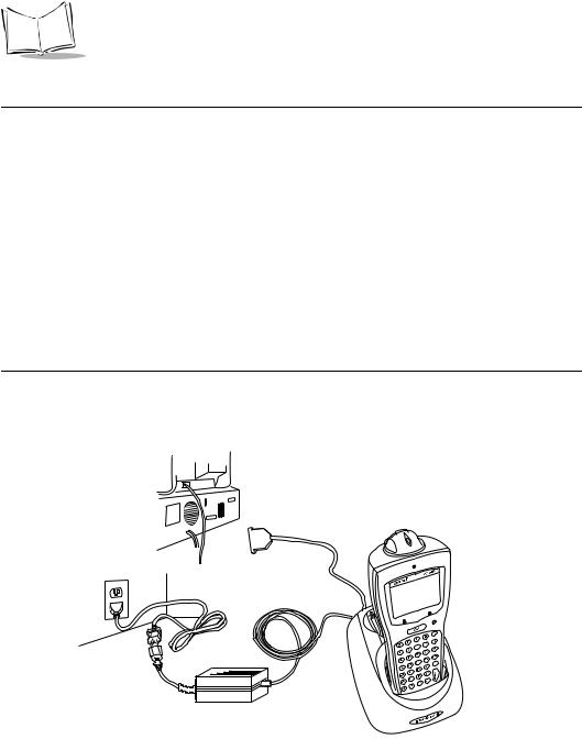
Connecting the Cables
To connect the CRD 61XX communications cables and power supply:
|
RJ-11 Modem Port |
Power Jack |
Serial Cable |
|
Figure 2-2. Connecting the Cables
1.Plug the RS-232 serial cable in the communications port located on the back of the cradle.
2.Connect the serial cable’s other end to the host PC’s communications port.
3.Connect the power jack to the cradle’s AC power port.
4.Connect the power supply to a line cord.
5.Insert the line cord’s connector in a standard electrical outlet.
Connecting the Internal Modem
Some cradles use an optional internal modem that communicates at rates of up to 14,400 bps (with v.32 bit data compression). It can be connected directly to a telephone line through the RJ-11 port shown in Figure 2-2.
Note: The four-slot cradle does not have an internal modem.
2-3

PDT 6100 Product Reference Guide
To connect the internal modem:
1.Connect the phone cord into the RJ-11 port on the back of the cradle.
2.Connect the other end of the phone cord into the wall phone jack.
Caution
When connecting the internal modem to the phone line, always connect the phone line to the cradle first, then to the wall phone jack. When removing the connection, always remove the telephone line from the wall phone jack, then remove from the cradle.
There are specific firmware settings which are used to configure the modem’s hardware and software for proper operation and regulatory compliance. The terminal’s application can control these settings and enable you to view and amend the settings for country/region, pulse/tone dialing, or repeat dial timing. Incorrectly defining these settings can lead to illegal use of the modem and can create unreliable operation. The application developer should consult the Series 3000 Application Programmer’s Reference Manual for correct settings.
Connecting to the Telephone Network
A compliant telephone cord is required with an RJ-11 plug connection to the modem, terminated with an appropriate and correctly wired local telecom connector compatible with the telephone network. Such a cable may be obtained from your local supplier. Alternately, compliant RJ-11 plugs to RJ-11 plug cables may be used with a range of adapters for locations such as Europe.
2-4

Chapter 3
Batch and Spectrum One Terminal Setup
Introduction
Before using the PDT 6100 system, perform the following procedures:
!Set up the CRD 6100 cradle (refer to Chapter 2, Installing the Hardware)
!Install the battery (refer to Chapter 6, Maintaining the Terminal)
!Charge the battery (refer to Chapter 6, Maintaining the Terminal)
!Load the system files and application(s).
Hardware Requirements
Hardware required for performing initialization includes:
!Host PC
!RS-232 serial null modem cable
!PDT 6100 terminal
!Cradle with power supply.
Refer to Chapter 2, Installing the Hardware for setting up the cradle for communication.
3-1
PDT 6100 Product Reference Guide
Communications
For terminals being used in a direct communications (batch) environment or a Spectrum One network environment, applications are transferred from a host computer over a communications line to the terminal.
This procedure uses the SENDHEX program on the host computer and the Program Loader function (from Command Mode) on the PDT 6100.
Programs are stored in the terminal’s nonvolatile memory (NVM), also called the application EEPROM.
For details on SENDHEX, refer to the Series 3000 Application Programmer's Manual.
Other software may be used in place of the SENDHEX program.
Set up for Initialization
1.Verify that the cradle is connected to the host PC. Refer to Chapter 2, Installing the Hardware.
2.Place the PDT 6100 in the cradle (refer to Figure 3-1) and power it off.
33222011.eps
Figure 3-1. Placing the PDT 6100 in the Cradle
3-2

Batch and Spectrum One Terminal Setup
Loading an Application
To download an application, initiate the communications software on the host computer and PDT 6100.
Note: To cancel communications at any time during the session, press CLEAR on the PDT 6100. The session stops immediately.
Communication parameters specified on host and PDT 6100 must match. These parameters typically are:
38400 bps
7 bit data Odd parity None
The PDT 6100 must be connected to the host through a cradle to program the NVM.
Initiate Host Communications Software on the PC
1.Power on host computer.
2.Start the communication program.
3.At a DOS prompt, enter the SENDHEX command:
sendhex pgmname 38400 com2
where:
SENDHEX |
is the command. |
pgmname |
is the application being loaded (.hex extension is optional). |
parameters |
are the communications parameters following the program name. |
|
Parameters include baud rate, communications port, data bits, parity, |
|
and flow control. To accept the default parameters, do not enter a value. |
In the example, baud rate is set to 38400 bps and communications port to COM2. The default values are accepted for the remaining parameters.
3-3

PDT 6100 Product Reference Guide
Note: Versions of SENDHEX earlier than 3.0 do not support flow control. If you use an earlier version and encounter communication errors, use a lower baud rate. If you use a later version of SENDHEX and have communications errors, try setting flow control to XON/XOFF.
4. SENDHEX displays the prompt:
Press <ENTER> to begin
communications.
5.Do NOT press <ENTER> yet. Before starting communications (refer to Starting Communications on page 3-6), set up the PDT 6100 for loading a HEX image as directed in the following sections.
Initiate Terminal Communications
1.Boot the PDT 6100 to command mode. For the 22-Key terminal:
"Press and hold <SEND> and <9>.
"Press and release PWR.
"Release <SEND> and <9>.
For the 35-Key terminal:
"Press and hold <BKSP> and <SHIFT>.
"Press and release PWR.
"Release <BKSP> and <SHIFT>.
For the 46-Key terminal:
"Press and hold <F> and <I>.
"Press and release <PWR>.
"Release <F> and <I>.
The display shows the function selector screen:
COMMAND MODE
Select function
Self Test
3-4

Batch and Spectrum One Terminal Setup
2.Scroll through Command Mode options using UpArrow or DownArrow until “Program loader” is displayed. Press <ENTER>.
3.The PDT 6100 displays:
Program loader
WARNING: NVM
WILL BE ERASED
CONTINUE? <ENT>
Before loading the new application, erase NVM’s original contents.
Note: To cancel this operation, press <CLEAR>.
4.Press <ENTER> to erase the NVM.
Wait while the NVM is erased. When complete, the program prompts for the communications parameters.
5.Baud Rate.The PDT 6100 displays:
Comm Parameters
Baud
5 38400
Scroll through the list using UpArrow or DownArrow. When the correct rate is displayed (38400 is recommended), press <ENTER>.
6. Data Bits. The PDT 6100 displays:
Comm Parameters
Data Bits 7
Press <7> (recommended) or <8> to specify data bits, or scroll through the list using UpArrow and DownArrow. Press <ENTER> when the correct value is displayed.
Note: If 8 data bits is selected, the program selects “No parity” and skips the next step.
3-5

PDT 6100 Product Reference Guide
7. Parity. If 7 data bits is selected, the PDT 6100 displays:
Comm Parameters
Parity
Odd
Press the first letter of a parity option (Even, Odd, None, Space, or Mark), or scroll using UpArrow and DownArrow and press <ENTER> when the correct value is displayed.
8. Flow Control. The PDT 6100 displays:
Comm Parameters
Flow Control
None
Press the first letter of a flow control option (None, Xon/Xoff, or RTS/CTS), or scroll using UpArrow or DownArrow and press <ENTER> when the correct value is displayed.
9. Go to Starting Communications to continue.
Starting Communications
The PDT 6100 is ready to receive the program from the host PC and displays:
Comm Parameters
Start? <ENT>
1.Press <ENTER> on the PDT 6100. The PDT 6100 waits a few seconds for the host PC to initiate communications. While waiting, the PDT 6100 displays:
Comm Parameters
Receiving:
If the host is not ready or the cable is not connected between the host PC and cradle, the terminal displays:
Awaiting DSR
3-6

Batch and Spectrum One Terminal Setup
2.Press <ENTER> on the host computer. SENDHEX begins transmitting the program image. When communications are established, the PDT 6100 displays:
Program loader
Receiving: XXXX
where XXXX is the program segment address being transferred.
3. When the transmission is complete, the PDT 6100 displays:
Program loader
Status 0000
A status of 0000 (all zeros) indicates a successful transfer. Other status values indicate an error. These values are provided in Appendix C, Communications Status Codes.
Ending Communications
To return to the Command Mode main menu:
1.Press <CLEAR> on the PDT 6100.
2.Power down the PDT 6100.
3.Remove the PDT 6100 from the cradle.
4.Reboot the PDT 6100 using the appropriate cold boot sequence described in Booting the Terminal on page 5-4.
3-7
Loading...