

Page 1

About This Manual
Table of Contents
Index
Copyright
Series 6800
Product Reference Guide
70-32645-01
Revision A
April 1998
Page 2

Series 6800
Product Reference Guide
70-32645-01
Revision A
April 1998
Page 3

1998
by Symbol Technologies, Inc. All rights reserved.
No part of this publication may be reproduced or used in any form, or by any electrical or
mechanical means, without permission in writing from Symbol. This includes electronic or
mechanical means, such as photocopying, recording, or information storage and retrieval
systems. The material in this manual is subject to change without notice.
The software is provided strictly on an “as is” basis. All software, including firmware,
furnished to the user is on a licensed basis. Symbol grants to the user a non-transferable and
non-exclusive license to use each software or firmware program delivered hereunder (licensed
program). Except as noted below, such license may not be assigned, sublicensed, or otherwise
transferred by the user without prior written consent of Symbol. No right to copy a licensed
program in whole or in part is granted, except as permitted under copyright law. The user
shall not modify, merge, or incorporate any form or portion of a licensed program with other
program material, create a derivative work from a licensed program, or use a licensed
program in a network without written permission from Symbol. The user agrees to maintain
Symbol’s copyright notice on the licensed programs delivered hereunder, and to include the
same on any authorized copies it makes, in whole or in part. The user agrees not to
decompile, disassemble, decode, or reverse engineer any licensed program delivered to the
user or any portion thereof.
Symbol reserves the right to make changes to any software or product to improve reliability,
function, or design.
Symbol does not assume any product liability arising out of, or in connection with, the
application or use of any product, circuit, or application described herein.
No license is granted, either expressly or by implication, estoppel, or otherwise under any
Symbol Technologies, Inc., intellectual property rights. An implied license only exists for
equipment, circuits, and subsystems contained in Symbol products.
Symbol, Spectrum One, and Spectrum24 are registered trademarks of Symbol Technologies,
Inc. Other product names mentioned in this manual may be trademarks or registered
trademarks of their respective companies and are hereby acknowledged.
Symbol Technologies, Inc.
One Symbol Plaza
Holtsville, New York 11742-1300
http://www.symbol.com
ii
Page 4

Contents
About This Manual
Notational Conventions . . . . . . . . . . . . . . . . . . . . . . . . . . . . . . . . . . . . . . . . . . . . . . . . . . . . . . . . . . ix
Related Publications. . . . . . . . . . . . . . . . . . . . . . . . . . . . . . . . . . . . . . . . . . . . . . . . . . . . . . . . . . . . . .x
Documents Available from Symbol Technologies . . . . . . . . . . . . . . . . . . . . . . . . . . . . . . . . . . . . x
Service Information . . . . . . . . . . . . . . . . . . . . . . . . . . . . . . . . . . . . . . . . . . . . . . . . . . . . . . . . . . . . . xi
Symbol Support Center . . . . . . . . . . . . . . . . . . . . . . . . . . . . . . . . . . . . . . . . . . . . . . . . . . . . . . . xi
USA. . . . . . . . . . . . . . . . . . . . . . . . . . . . . . . . . . . . . . . . . . . . . . . . . . . . . . . . . . . . . . . . . . . . . . xi
Canada . . . . . . . . . . . . . . . . . . . . . . . . . . . . . . . . . . . . . . . . . . . . . . . . . . . . . . . . . . . . . . . . . . . xi
Europe. . . . . . . . . . . . . . . . . . . . . . . . . . . . . . . . . . . . . . . . . . . . . . . . . . . . . . . . . . . . . . . . . . . . xii
Asia. . . . . . . . . . . . . . . . . . . . . . . . . . . . . . . . . . . . . . . . . . . . . . . . . . . . . . . . . . . . . . . . . . . . . . xii
Chapter 1. The Series 68XX System
Terminal Parts and Basic Operation. . . . . . . . . . . . . . . . . . . . . . . . . . . . . . . . . . . . . . . . . . . . . . . . 1-2
Display . . . . . . . . . . . . . . . . . . . . . . . . . . . . . . . . . . . . . . . . . . . . . . . . . . . . . . . . . . . . . . . . . . 1-3
Keyboard. . . . . . . . . . . . . . . . . . . . . . . . . . . . . . . . . . . . . . . . . . . . . . . . . . . . . . . . . . . . . . . . . 1-3
Battery Pack Compartment . . . . . . . . . . . . . . . . . . . . . . . . . . . . . . . . . . . . . . . . . . . . . . . . . . . 1-3
Battery Recharge Contacts . . . . . . . . . . . . . . . . . . . . . . . . . . . . . . . . . . . . . . . . . . . . . . . . . . . 1-3
Optical Connector. . . . . . . . . . . . . . . . . . . . . . . . . . . . . . . . . . . . . . . . . . . . . . . . . . . . . . . . . . 1-3
Trigger . . . . . . . . . . . . . . . . . . . . . . . . . . . . . . . . . . . . . . . . . . . . . . . . . . . . . . . . . . . . . . . . . . 1-3
Wrist Strap . . . . . . . . . . . . . . . . . . . . . . . . . . . . . . . . . . . . . . . . . . . . . . . . . . . . . . . . . . . . . . . 1-3
Accessories . . . . . . . . . . . . . . . . . . . . . . . . . . . . . . . . . . . . . . . . . . . . . . . . . . . . . . . . . . . . . . . . . . . 1-4
Battery Chargers . . . . . . . . . . . . . . . . . . . . . . . . . . . . . . . . . . . . . . . . . . . . . . . . . . . . . . . . . . . 1-4
Cradles . . . . . . . . . . . . . . . . . . . . . . . . . . . . . . . . . . . . . . . . . . . . . . . . . . . . . . . . . . . . . . . . . . 1-4
UBC Chargers . . . . . . . . . . . . . . . . . . . . . . . . . . . . . . . . . . . . . . . . . . . . . . . . . . . . . . . . . . . . . 1-4
Printer Interface Module (PIM). . . . . . . . . . . . . . . . . . . . . . . . . . . . . . . . . . . . . . . . . . . . . . . . 1-4
PC Adapter . . . . . . . . . . . . . . . . . . . . . . . . . . . . . . . . . . . . . . . . . . . . . . . . . . . . . . . . . . . . . . . 1-4
Radio and Network Options. . . . . . . . . . . . . . . . . . . . . . . . . . . . . . . . . . . . . . . . . . . . . . . . . . 1-5
Unpacking . . . . . . . . . . . . . . . . . . . . . . . . . . . . . . . . . . . . . . . . . . . . . . . . . . . . . . . . . . . . . . . . . . . 1-5
Before You Use the Terminal . . . . . . . . . . . . . . . . . . . . . . . . . . . . . . . . . . . . . . . . . . . . . . . . . . . . . 1-6
Install and Charge the Battery. . . . . . . . . . . . . . . . . . . . . . . . . . . . . . . . . . . . . . . . . . . . . . . . . 1-6
Load the Appropriate Software. . . . . . . . . . . . . . . . . . . . . . . . . . . . . . . . . . . . . . . . . . . . . . . . 1-6
iii
Page 5

Series 6800 Product Reference Guide
Chapter 2. Hardware Setup
38/6865 and 38/6866 Cradles . . . . . . . . . . . . . . . . . . . . . . . . . . . . . . . . . . . . . . . . . . . . . . . . . . . . .2-2
Parts of the 38/6865 Cradle . . . . . . . . . . . . . . . . . . . . . . . . . . . . . . . . . . . . . . . . . . . . . . . . . . . 2-3
Parts of the 38/6866 Cradle . . . . . . . . . . . . . . . . . . . . . . . . . . . . . . . . . . . . . . . . . . . . . . . . . . . 2-3
Wall Mounting the 38/6865. . . . . . . . . . . . . . . . . . . . . . . . . . . . . . . . . . . . . . . . . . . . . . . . . . .2-4
Table Mounting the 38/6866 . . . . . . . . . . . . . . . . . . . . . . . . . . . . . . . . . . . . . . . . . . . . . . . . . . 2-6
Wall Mounting the 38/6866. . . . . . . . . . . . . . . . . . . . . . . . . . . . . . . . . . . . . . . . . . . . . . . . . . .2-6
Connecting Power for the 38/6865 and 38/6866 . . . . . . . . . . . . . . . . . . . . . . . . . . . . . . . . . . .2-7
Connecting for Data Communications . . . . . . . . . . . . . . . . . . . . . . . . . . . . . . . . . . . . . . . . . . .2-8
38/6860 CCM . . . . . . . . . . . . . . . . . . . . . . . . . . . . . . . . . . . . . . . . . . . . . . . . . . . . . . . . . . . . . . . .2-10
Parts of the CCM 38/6860 . . . . . . . . . . . . . . . . . . . . . . . . . . . . . . . . . . . . . . . . . . . . . . . . . . .2-10
Wall Mounting the CCM . . . . . . . . . . . . . . . . . . . . . . . . . . . . . . . . . . . . . . . . . . . . . . . . . . . .2-11
Coupling CCMs . . . . . . . . . . . . . . . . . . . . . . . . . . . . . . . . . . . . . . . . . . . . . . . . . . . . . . . . . . .2-12
Connecting Power to the 38/6860 CCM. . . . . . . . . . . . . . . . . . . . . . . . . . . . . . . . . . . . . . . . .2-13
Connecting the CCM for Serial Communications. . . . . . . . . . . . . . . . . . . . . . . . . . . . . . . . . . 2-14
Daisy-Chaining Two or More CCMs . . . . . . . . . . . . . . . . . . . . . . . . . . . . . . . . . . . . . . . . . . .2-14
The PC Adapter . . . . . . . . . . . . . . . . . . . . . . . . . . . . . . . . . . . . . . . . . . . . . . . . . . . . . . . . . . . . . .2-16
Parts of the PC Adapter . . . . . . . . . . . . . . . . . . . . . . . . . . . . . . . . . . . . . . . . . . . . . . . . . . . . .2-16
Connecting the PC Adapter to 68XX and Serial Device . . . . . . . . . . . . . . . . . . . . . . . . . . . . .2-17
Chapter 3. Batch and Spectrum One Terminal Setup
Introduction. . . . . . . . . . . . . . . . . . . . . . . . . . . . . . . . . . . . . . . . . . . . . . . . . . . . . . . . . . . . . . . . . . .3-1
Hardware Requirements . . . . . . . . . . . . . . . . . . . . . . . . . . . . . . . . . . . . . . . . . . . . . . . . . . . . . . . . .3-1
Communications . . . . . . . . . . . . . . . . . . . . . . . . . . . . . . . . . . . . . . . . . . . . . . . . . . . . . . . . . . .3-2
Loading the Program. . . . . . . . . . . . . . . . . . . . . . . . . . . . . . . . . . . . . . . . . . . . . . . . . . . . . . . . . . . .3-3
Initiate Host Communications Software. . . . . . . . . . . . . . . . . . . . . . . . . . . . . . . . . . . . . . . . . .3-3
Chapter 4. Spectrum24 RF Terminal Setup
Spectrum24 Terminals. . . . . . . . . . . . . . . . . . . . . . . . . . . . . . . . . . . . . . . . . . . . . . . . . . . . . . . . . . .4-1
Accessing the Flash Disk. . . . . . . . . . . . . . . . . . . . . . . . . . . . . . . . . . . . . . . . . . . . . . . . . . . . . . 4-1
Standard Spectrum24 Software . . . . . . . . . . . . . . . . . . . . . . . . . . . . . . . . . . . . . . . . . . . . . . . . . . . . 4-2
Boot Options & Internet Addressing . . . . . . . . . . . . . . . . . . . . . . . . . . . . . . . . . . . . . . . . . . . . . . . .4-2
Initializing the Series . . . . . . . . . . . . . . . . . . . . . . . . . . . . . . . . . . . . . . . . . . . . . . . . . . . . . . . . . . . .4-3
Initiating Network Connection. . . . . . . . . . . . . . . . . . . . . . . . . . . . . . . . . . . . . . . . . . . . . . . . 4-11
Installing Application Software on Flash Disk . . . . . . . . . . . . . . . . . . . . . . . . . . . . . . . . . . . . . . . .4-12
Initiate Host Communications on the PC . . . . . . . . . . . . . . . . . . . . . . . . . . . . . . . . . . . . . . . .4-12
Running _L.BAT . . . . . . . . . . . . . . . . . . . . . . . . . . . . . . . . . . . . . . . . . . . . . . . . . . . . . . . . . .4-13
Updating System Software on Flash Disk. . . . . . . . . . . . . . . . . . . . . . . . . . . . . . . . . . . . . . . . . . . . 4-15
Option: Using _L.BAT to Update System Software. . . . . . . . . . . . . . . . . . . . . . . . . . . . . . . . . 4-15
Initiate Host Communications on the PC . . . . . . . . . . . . . . . . . . . . . . . . . . . . . . . . . . . . . . . .4-15
Initiate Terminal Communications. . . . . . . . . . . . . . . . . . . . . . . . . . . . . . . . . . . . . . . . . . . . . 4-16
iv
Page 6

Table of Contents
Compatibility Issues When Updating. . . . . . . . . . . . . . . . . . . . . . . . . . . . . . . . . . . . . . . . . . . 4-19
Multiple Applications on the Same Terminal. . . . . . . . . . . . . . . . . . . . . . . . . . . . . . . . . . . . . 4-20
Chapter 5. Operating the Series 68XX
Overview . . . . . . . . . . . . . . . . . . . . . . . . . . . . . . . . . . . . . . . . . . . . . . . . . . . . . . . . . . . . . . . . . . . . 5-1
Normal Power On Techniques . . . . . . . . . . . . . . . . . . . . . . . . . . . . . . . . . . . . . . . . . . . . . . . . . . . . 5-2
Removal From a Cradle . . . . . . . . . . . . . . . . . . . . . . . . . . . . . . . . . . . . . . . . . . . . . . . . . . . . . 5-2
Keyboard. . . . . . . . . . . . . . . . . . . . . . . . . . . . . . . . . . . . . . . . . . . . . . . . . . . . . . . . . . . . . . . . . 5-2
Real-Time Clock . . . . . . . . . . . . . . . . . . . . . . . . . . . . . . . . . . . . . . . . . . . . . . . . . . . . . . . . . . . 5-2
Laser Trigger. . . . . . . . . . . . . . . . . . . . . . . . . . . . . . . . . . . . . . . . . . . . . . . . . . . . . . . . . . . . . . 5-2
Restoring Power After Automatic Shutdown. . . . . . . . . . . . . . . . . . . . . . . . . . . . . . . . . . . . . . 5-3
Power Off. . . . . . . . . . . . . . . . . . . . . . . . . . . . . . . . . . . . . . . . . . . . . . . . . . . . . . . . . . . . . . . . . . . . 5-3
Forced Power Off . . . . . . . . . . . . . . . . . . . . . . . . . . . . . . . . . . . . . . . . . . . . . . . . . . . . . . . . . . 5-3
Restarting After a Forced Power Off. . . . . . . . . . . . . . . . . . . . . . . . . . . . . . . . . . . . . . . . . . . . 5-3
Booting a Series 68XX . . . . . . . . . . . . . . . . . . . . . . . . . . . . . . . . . . . . . . . . . . . . . . . . . . . . . . . . . . 5-4
Warm Boot . . . . . . . . . . . . . . . . . . . . . . . . . . . . . . . . . . . . . . . . . . . . . . . . . . . . . . . . . . . . . . . 5-4
Cold Boot . . . . . . . . . . . . . . . . . . . . . . . . . . . . . . . . . . . . . . . . . . . . . . . . . . . . . . . . . . . . . . . . 5-4
Boot to Command Mode. . . . . . . . . . . . . . . . . . . . . . . . . . . . . . . . . . . . . . . . . . . . . . . . . . . . . 5-5
Adjusting the Screen Contrast. . . . . . . . . . . . . . . . . . . . . . . . . . . . . . . . . . . . . . . . . . . . . . . . . . . . . 5-6
Display Contrast . . . . . . . . . . . . . . . . . . . . . . . . . . . . . . . . . . . . . . . . . . . . . . . . . . . . . . . . . . . 5-6
Back Lighting . . . . . . . . . . . . . . . . . . . . . . . . . . . . . . . . . . . . . . . . . . . . . . . . . . . . . . . . . . . . . 5-6
Entering Data. . . . . . . . . . . . . . . . . . . . . . . . . . . . . . . . . . . . . . . . . . . . . . . . . . . . . . . . . . . . . . . . . 5-6
The Keyboard . . . . . . . . . . . . . . . . . . . . . . . . . . . . . . . . . . . . . . . . . . . . . . . . . . . . . . . . . . . . . 5-6
Using the Keyboard. . . . . . . . . . . . . . . . . . . . . . . . . . . . . . . . . . . . . . . . . . . . . . . . . . . . . . . . . 5-6
Keyboard Key Definitions . . . . . . . . . . . . . . . . . . . . . . . . . . . . . . . . . . . . . . . . . . . . . . . . . . . . 5-9
Scanning. . . . . . . . . . . . . . . . . . . . . . . . . . . . . . . . . . . . . . . . . . . . . . . . . . . . . . . . . . . . . . . . . . . . 5-11
Entering Data Using the Laser Scanner . . . . . . . . . . . . . . . . . . . . . . . . . . . . . . . . . . . . . . . . . 5-11
Scanning Considerations . . . . . . . . . . . . . . . . . . . . . . . . . . . . . . . . . . . . . . . . . . . . . . . . . . . . 5-12
Communications . . . . . . . . . . . . . . . . . . . . . . . . . . . . . . . . . . . . . . . . . . . . . . . . . . . . . . . . . . . . . 5-14
With a Host. . . . . . . . . . . . . . . . . . . . . . . . . . . . . . . . . . . . . . . . . . . . . . . . . . . . . . . . . . . . . . 5-14
With a Printer . . . . . . . . . . . . . . . . . . . . . . . . . . . . . . . . . . . . . . . . . . . . . . . . . . . . . . . . . . . . 5-14
RF Network Communications. . . . . . . . . . . . . . . . . . . . . . . . . . . . . . . . . . . . . . . . . . . . . . . . 5-15
Chapter 6. Maintaining the Series 68XX
Batteries . . . . . . . . . . . . . . . . . . . . . . . . . . . . . . . . . . . . . . . . . . . . . . . . . . . . . . . . . . . . . . . . . . . . . 6-1
Battery Life . . . . . . . . . . . . . . . . . . . . . . . . . . . . . . . . . . . . . . . . . . . . . . . . . . . . . . . . . . . . . . . 6-1
When to Replace or Recharge the Battery . . . . . . . . . . . . . . . . . . . . . . . . . . . . . . . . . . . . . . . . 6-2
NiCd Battery Pack . . . . . . . . . . . . . . . . . . . . . . . . . . . . . . . . . . . . . . . . . . . . . . . . . . . . . . . . . . . . . 6-3
Replacement Battery Packs . . . . . . . . . . . . . . . . . . . . . . . . . . . . . . . . . . . . . . . . . . . . . . . . . . . 6-3
Removing the NiCd Battery Pack . . . . . . . . . . . . . . . . . . . . . . . . . . . . . . . . . . . . . . . . . . . . . . 6-3
Installing the NiCd Battery Pack . . . . . . . . . . . . . . . . . . . . . . . . . . . . . . . . . . . . . . . . . . . . . . . 6-5
Charging the NiCd Battery Pack . . . . . . . . . . . . . . . . . . . . . . . . . . . . . . . . . . . . . . . . . . . . . . . 6-6
v
Page 7

Series 6800 Product Reference Guide
Battery Charging Tips. . . . . . . . . . . . . . . . . . . . . . . . . . . . . . . . . . . . . . . . . . . . . . . . . . . . . . . .6-8
Cleaning . . . . . . . . . . . . . . . . . . . . . . . . . . . . . . . . . . . . . . . . . . . . . . . . . . . . . . . . . . . . . . . . . . . . .6-9
Storage . . . . . . . . . . . . . . . . . . . . . . . . . . . . . . . . . . . . . . . . . . . . . . . . . . . . . . . . . . . . . . . . . . .6-9
Chapter 7. Error Recovery and Troubleshooting
Error Messages . . . . . . . . . . . . . . . . . . . . . . . . . . . . . . . . . . . . . . . . . . . . . . . . . . . . . . . . . . . . . . . .7-2
Troubleshooting Guide . . . . . . . . . . . . . . . . . . . . . . . . . . . . . . . . . . . . . . . . . . . . . . . . . . . . . . . . . .7-3
Startup Failure . . . . . . . . . . . . . . . . . . . . . . . . . . . . . . . . . . . . . . . . . . . . . . . . . . . . . . . . . . . . . 7-3
Boot Failure Messages . . . . . . . . . . . . . . . . . . . . . . . . . . . . . . . . . . . . . . . . . . . . . . . . . . . . . . .7-3
Spectrum24 Terminal. . . . . . . . . . . . . . . . . . . . . . . . . . . . . . . . . . . . . . . . . . . . . . . . . . . . . . . .7-4
Self Test Function . . . . . . . . . . . . . . . . . . . . . . . . . . . . . . . . . . . . . . . . . . . . . . . . . . . . . . . . . . . . . .7-5
Running Self Test . . . . . . . . . . . . . . . . . . . . . . . . . . . . . . . . . . . . . . . . . . . . . . . . . . . . . . . . . . .7-5
Self Test Summaries . . . . . . . . . . . . . . . . . . . . . . . . . . . . . . . . . . . . . . . . . . . . . . . . . . . . . . . . . 7-5
Keyboard Test . . . . . . . . . . . . . . . . . . . . . . . . . . . . . . . . . . . . . . . . . . . . . . . . . . . . . . . . . . . . .7-6
Memory Transfer Program . . . . . . . . . . . . . . . . . . . . . . . . . . . . . . . . . . . . . . . . . . . . . . . . . . . . . . .7-7
Hardware Setup . . . . . . . . . . . . . . . . . . . . . . . . . . . . . . . . . . . . . . . . . . . . . . . . . . . . . . . . . . . .7-7
Set Communications Parameters. . . . . . . . . . . . . . . . . . . . . . . . . . . . . . . . . . . . . . . . . . . . . . . .7-7
Scanning Problems. . . . . . . . . . . . . . . . . . . . . . . . . . . . . . . . . . . . . . . . . . . . . . . . . . . . . . . . . . . . . 7-11
What If... . . . . . . . . . . . . . . . . . . . . . . . . . . . . . . . . . . . . . . . . . . . . . . . . . . . . . . . . . . . . . . . .7-11
Appendix A. Null Modem Pin-outs
Null Modem Pin-Outs for Full Duplex . . . . . . . . . . . . . . . . . . . . . . . . . . . . . . . . . . . . . . . . . . . . . A-1
Null Modem Pin-outs for Half-Duplex . . . . . . . . . . . . . . . . . . . . . . . . . . . . . . . . . . . . . . . . . . . . . A-2
Appendix B. Communications Status Codes
Appendix C. Specifications
Environment . . . . . . . . . . . . . . . . . . . . . . . . . . . . . . . . . . . . . . . . . . . . . . . . . . . . . . . . . . . . . . . . . C-1
RF Communications . . . . . . . . . . . . . . . . . . . . . . . . . . . . . . . . . . . . . . . . . . . . . . . . . . . . . . . . . . . C-2
Scanning Decode Zones. . . . . . . . . . . . . . . . . . . . . . . . . . . . . . . . . . . . . . . . . . . . . . . . . . . . . . . . . C-3
Standard. . . . . . . . . . . . . . . . . . . . . . . . . . . . . . . . . . . . . . . . . . . . . . . . . . . . . . . . . . . . . . . . . C-3
Appendix D. Boot-Up Quick Reference
Appendix E. Spectrum24 Network and Flash Disk Utilities
Introduction. . . . . . . . . . . . . . . . . . . . . . . . . . . . . . . . . . . . . . . . . . . . . . . . . . . . . . . . . . . . . . . . . . .E-1
CFG24. . . . . . . . . . . . . . . . . . . . . . . . . . . . . . . . . . . . . . . . . . . . . . . . . . . . . . . . . . . . . . . . . . . . . . .E-2
Syntax . . . . . . . . . . . . . . . . . . . . . . . . . . . . . . . . . . . . . . . . . . . . . . . . . . . . . . . . . . . . . . . . . . .E-2
Description. . . . . . . . . . . . . . . . . . . . . . . . . . . . . . . . . . . . . . . . . . . . . . . . . . . . . . . . . . . . . . . .E-2
vi
Page 8

Table of Contents
BOOTP . . . . . . . . . . . . . . . . . . . . . . . . . . . . . . . . . . . . . . . . . . . . . . . . . . . . . . . . . . . . . . . . . . . . . E-9
Description . . . . . . . . . . . . . . . . . . . . . . . . . . . . . . . . . . . . . . . . . . . . . . . . . . . . . . . . . . . . . . . E-9
Output . . . . . . . . . . . . . . . . . . . . . . . . . . . . . . . . . . . . . . . . . . . . . . . . . . . . . . . . . . . . . . . . . E-10
STAT24 . . . . . . . . . . . . . . . . . . . . . . . . . . . . . . . . . . . . . . . . . . . . . . . . . . . . . . . . . . . . . . . . . . . . E-11
Description . . . . . . . . . . . . . . . . . . . . . . . . . . . . . . . . . . . . . . . . . . . . . . . . . . . . . . . . . . . . . . E-11
DIAG24 . . . . . . . . . . . . . . . . . . . . . . . . . . . . . . . . . . . . . . . . . . . . . . . . . . . . . . . . . . . . . . . . . . . . E-13
Syntax. . . . . . . . . . . . . . . . . . . . . . . . . . . . . . . . . . . . . . . . . . . . . . . . . . . . . . . . . . . . . . . . . . E-13
Description . . . . . . . . . . . . . . . . . . . . . . . . . . . . . . . . . . . . . . . . . . . . . . . . . . . . . . . . . . . . . . E-13
Ping Tests . . . . . . . . . . . . . . . . . . . . . . . . . . . . . . . . . . . . . . . . . . . . . . . . . . . . . . . . . . . . . . . E-16
Field Diagnostics. . . . . . . . . . . . . . . . . . . . . . . . . . . . . . . . . . . . . . . . . . . . . . . . . . . . . . . . . . E-18
FLASH.BAT. . . . . . . . . . . . . . . . . . . . . . . . . . . . . . . . . . . . . . . . . . . . . . . . . . . . . . . . . . . . . . . . . E-19
Deleting Files from Flash Disk. . . . . . . . . . . . . . . . . . . . . . . . . . . . . . . . . . . . . . . . . . . . . . . . E-19
Copying Files to Flash Disk. . . . . . . . . . . . . . . . . . . . . . . . . . . . . . . . . . . . . . . . . . . . . . . . . . E-20
Renaming Files on Flash Disk . . . . . . . . . . . . . . . . . . . . . . . . . . . . . . . . . . . . . . . . . . . . . . . . E-20
vii
Page 9

Series 6800 Product Reference Guide
viii
Page 10

About This Manual
The
Series 6800 Product Reference Guide
initialization, operation, troubleshooting, and maintenance of the Series 68XX terminal.
Notational Conventions
The following conventions are used in this document:
t
"Operator" and "User" refer to anyone using an application on a Series 68XX
terminal.
t
"PC" refers to the IBM personal computer or compatible system that you are using
to develop applications.
t
"Terminal" refers to a Series 68XX hand-held computer.
t
"You" refers to the administrator who is using this manual as a reference aid to
install, configure, operate, maintain, and troubleshoot the Series 68XX.
t
Keystrokes in bold type indicate non-alphanumeric keystrokes on the PC.
t
Bold
type is used to identify menu items and input or text fields on a terminal screen.
t
Italics are used:
s
for the names of parameters in function prototypes and variable names in usage
and syntax descriptions
s
to highlight specific items in the general text
s
to identify chapters and sections in this and related documents
t
The piping symbol | has the effect of "or" when it is used to separate inline
parameters on a command line; i.e., it separates alternative values for parameters.
t
Bullets (•) indicate:
s
action items
s
lists of alternatives
s
lists of required steps that are not necessarily sequential
provides general instructions for setup,
ix
Page 11

Series 68XX Product Reference Guide
t
Sequential lists (e.g., those that describe step-by-step procedures) appear as
numbered lists.
Related Publications
The following is a list of documents and publications that you may find useful if you want to
know more about the Series 6800 terminals or about the tools and utilities that are available
for writing applications for the terminals.
Documents Available from Symbol Technologies
t
Series 6800 Quick Reference Guide
t
38/6860 Charging and Communications Module Quick Reference Guide
70-33400-XX
t
Cradle Base Unit 38/6865 Quick Reference Guide
t
Cradle Base Module 38/6866 Quick Reference Guide
t
Printer Interface Module Quick Reference Guide
t
Series 3000 Application Developer’s Kit (ADK):
s
Series 3000 Application Programmer's Guide
s
Series 3000 Application Programmer’s Reference Manual,
s
Series 3000 System Software Manual
s
Series 3000 Application Developer’s Library
t
Spectrum24 Access Point User’s Guide,
t
Spectrum24 Network Terminal Technical Reference Guide, 70-20193-XX
t
Novell LAN Workplace Reference Manual
t
Spectrum24 TNClient System Administrator’s Guide
t
Spectrum24 STEP Installation and Configuration Guide for Series 3000 Flash Disk
T erminals
, 70-20343-XX
, 70-32644-XX
,
, 70-33401-XX
, 70-33402-XX
, 59164-00-82
, 70-16308-XX
70-16309-XX
, 70-16310-XX
, 70-16311-XX
70-12057-XX
, 70-20288-XX
, 70-20244-XX
x
Page 12

About This Manual
Service Information
If you have a problem with your equipment, contact the Symbol Support Center. Before
calling, have the model number, serial number, and (if necessary) several of your bar code
symbols at hand.
Call the Support Center from a phone near the scanning equipment so that the service person
can try to talk you through your problem. If the equipment is found to be working properly
and the problem is symbol readability, the Support Center will request samples of your bar
codes for analysis at our plant.
If your problem cannot be solved over the phone, you may need to return your equipment
for servicing. If that is necessary, you will be given specific directions.
Note: Symbol Technologies is not responsible for any damages incurred
during shipment if the approved shipping container is not used.
Shipping the units improperly can possibly void the warranty. If the
original shipping container was not kept, contact Symbol to have
another sent to you.
Symbol Support Center
In the U.S.A, for service information, warranty information or technical assistance, call:
USA
SYMBOL SUPPORT CENTER
1-800-653-5350
Canada
Mississauga, Ontario
Canadian Headquarters
(905) 629-7226
xi
Page 13

Series 68XX Product Reference Guide
Europe
Symbol Place
Winnersh Triangle
Berkshire RG41 5TP UK
+44 1189 45 7222 (outside UK)
0 1189 45 7222 (inside UK)
Asia
Singapore
Symbol Technologies Asia, Inc.
337-6588 (Inside Singapore)
+65-337-6588 (Outside Singapore)
If you purchased your Symbol product from a Symbol Business Partner , contact that Business
Partner for service.
xii
Page 14

Chapter 1
The Series 68XX System
Symbol Technologies’ 68XX terminals are hand-held, battery-powered, portable data
collection devices. Data is entered from the 68XX’ s keyboard or through the integrated laser
scanner. As a remote terminal, the 68XX terminal collects and stores data that is later
uploaded to a host computer. The 6800 is a batch computer (no radio). Radio terminals
include the 6810 for use in a Spectrum One® network and the 6840 for the Spectrum24®
radio network environment.
68XX terminals use Caldera’s DR DOS™ operating system that is compatible with and
extends Microsoft® MS-DOS®. Although 68XX terminals are MS-DOS feature compatible,
they are not one hundred percent MS-DOS compatible. DR DOS provides access to a number
of commercially available programming tools. Additional programming tools are available
from Symbol for easier programming and access to special features.
1-1
Page 15

Series 68XX Product Reference Guide
Terminal Parts and Basic Operation
The following paragraphs describe the parts and accessories of the 68XX terminals. For
information on the 38/6860, 38/6865, and 38/6866 cradles, refer to the individual guides
listed in Related Publications. For information about the PC Adapter, refer to Chapter 2.
Scan LED
Display
Status LED
Status
-
-
+
Keyboard
=
Scan Window
T rigger
Battery Compartment
Wrist Strap
Battery
Recharge
Contacts
Optical
Connectors
Battery
Release
Button
Battery
Lock
1-2
Handle
(Battery
Compartment)
Figure 1-1. 68XX Terminal Parts
Battery Pack
Page 16

The Series 68XX System
Display
The display shows sixteen 21-character lines — alphabetical characters, numerals, and
symbols. Changing the contrast on the display is also available, as is back lighting if your
program allows it (refer to the section Back Lighting on page 5-6).
Keyboard
The keyboard contains all the operating and data entry keys. Refer to the section The
Keyboard on page 5-6 for more keyboard information.
Battery Pack Compartment
This compartment houses a NiCd battery pack or a carrier containing one 9-Volt alkaline
battery.
Battery Recharge Contacts
These contacts are used to recharge the battery pack in the terminal while it is in a cradle or
connected to the PC Adapter. Refer to Chapter 6 for more information on battery charging.
Optical Connector
The optical connector in the terminal aligns with the optical connector in the cradle terminal
slot or the Printer Interface Module (PIM) to enable the terminal to send and receive data or
to print.
Trigger
Pull the trigger to power on the terminal or to scan bar codes.
Wrist Strap
Place the wrist strap over your wrist to help you hold the terminal.
1-3
Page 17

Series 68XX Product Reference Guide
Accessories
The following accessories are available for 68XX terminals.
Battery Chargers
68XX terminals use a five-cell 780 mAh or six-cell 600 mAh (intrinsically safe) Nickel
Cadmium (NiCd) battery. NiCd batteries are charged using one of the charging accessories
listed below.
Cradles
Cradles combine a communications device and battery charger, and are available with either
one or four slots.
t 38/6860 Charging and Communications Module (CCM) — Four-slot module for
charging NiCd battery packs in the terminal and spare battery packs; also performs
communications between terminals and a host, modem, or printer. Refer to Chapter
2, Hardware Setup.
t 38/6865 Cradle Base Unit — Single-slot cradle for charging NiCd battery packs; also
performs communications between terminals and a host, a modem, or a printer.
Refer to Chapter 2, Hardware Setup.
t 38/6866 Cradle Base Module — Four-slot cradle for charging NiCd battery packs in
the terminal and for communicating between terminals and a host, a modem, or a
printer. Refer to Chapter 2, Hardware Setup.
UBC Chargers
The NiCd battery pack can be recharged in a UBC 1000 or 2000 battery charger.
Printer Interface Module (PIM)
The Printer Interface Module works with the PC Adapter to perform communications
between the terminal and a host PC or a printer without a cradle. Refer to the section The
PC Adapter on page 2-16.
PC Adapter
The PC Adapter works with the PIM to communicate with the host PC without a cradle or
to charge a NiCd battery pack in the terminal without a cradle. Refer to the section The PC
Adapter on page 2-16.
1-4
Page 18

The Series 68XX System
Radio and Network Options
Spectrum One Network
The 6810 includes an internal radio frequency transmitter/receiver for use in a Symbol
Spectrum One network.
Spectrum24 Network
The 6840 includes an internal radio frequency transmitter/receiver for use in a Symbol
Spectrum24 network.
Unpacking
Remove the clear protective tape from the display and the optical connector.
Save the shipping container for later storage or shipping. Inspect all equipment for damage
and make sure you have received everything listed on the packing slip.
If you find anything unsatisfactory or missing, contact your authorized customer support
representative immediately.
1-5
Page 19

Series 68XX Product Reference Guide
Before You Use the Terminal
The first time you use your 68XX terminal, or the first time you power it on after it has been
stored without the battery pack, follow these steps in order.
Install and Charge the Battery
1. Install a battery pack in the terminal. Refer to Chapter 6, Maintaining the Series
68XX, for instructions.
2. If you hear a repeated tone or see a message on the display, recharge or replace the
battery pack. Refer to Chapter 6, Maintaining the Series 68XX, for more
information.
Load the Appropriate Software
What software you load and how you load it depends on the environment in which it will be
used:
t If this unit is intended for use in batch applications (68XX) or in a Spectrum One
network environment (6810), refer to Chapter 3, Batch and Spectrum One T erminal
Setup, for information on downloading the software.
t If this unit is intended for use in a Spectrum24 network environment (6840), refer to
Chapter 4, Spectrum24 RF Terminal Setup, for information on downloading the
software.
1-6
Page 20

Chapter 2
Hardware Setup
The CRD 38/6865 and CRD 38/6866 cradles and Charging and Communications Module
(CCM) 38/6860 provide RS-232 communication, charging, and storage capability for the
Series 68XX terminals.
The PC adapter provides charging and communication capability for a Series 68XX terminal.
This chapter provides instructions for setting up each of these devices for charging the
68XX’s NiCd battery, and for communicating with a host, printer, or modem.
2-1
Page 21

Series 68XX Product Reference Guide
38/6865 and 38/6866 Cradles
Before attempting to mount or connect the cradles, verify that you have the following parts:
CRD 6865 CRD 6866
✓ Single-Slot Cradle with Charging Slot:
t US Kit: 3865-110
t International Kit: 3865-111
✓ AC Power Supply
t US:59915-00-00
t International: 60507-00-00
✓ Null Modem Cable, DB 25 Male to DB 25
Female (p/n 25-19297-01)
✓ Null Modem Cable DB25 Male to DB 9
Female (p/n 25-19299-01)
✓ Wall Mounting Kit (p/n 3866-000) ✓ Two Wall Mounting Kits (p/n 3866-000) per
✓ Four-Slot Cradle
t US Kit: 3866-100
t International Kit: 3866-101
✓ AC Power Supply
t US:60153-00-00
t International: 60174-00-00
✓ Null Modem Cable, DB 25 Male to DB 25
Female (p/n 25-19297-01)
✓ Null Modem Cable DB25 Male to DB 9
Female (p/n 25-19299-01)
✓ Chaining Interconnect Cable
(p/n 60427-00-00)
38/6866
2-2
Page 22

Parts of the 38/6865 Cradle
Figure 2-1 shows the parts of the CRD 38/6865.
Screw Hole
Covers
Optical
Connectors
Battery Contacts
Spare Battery
Charging Slot
Hardware Setup
Power Port
Serial Port
CHARGING
LED
COMM
LED
Figure 2-1. Parts of the CRD 38/6865
Parts of the 38/6866 Cradle
Figure 2-2 shows the parts of the CRD 38/6866.
Power Port
Serial Port
Optical
Connectors
LED
COMM
LED
CHARGING
Figure 2-2. Parts of the CRD38/6866
Battery
Contacts
Screw Hole
Covers
2-3
Page 23

Series 68XX Product Reference Guide
Wall Mounting the 38/6865
The CRD 38/6865 can be wall-mounted on a wall bracket for convenience. To wall-mount
the 38/6865:
1. Mark where you want the cradle positioned on the wall.
2. Using a fastener appropriate to the wall construction, insert and secure the fastener
(Figure 2-3). Let the head protrude slightly.
Figure 2-3. Wall Mounting the 38/6865
3. Slide the bracket down over the head of the fastener.
4. Remove the black tape covers from the cradle screw holes (Figure 2-4).
2-4
Figure 2-4. Removing the Tape Covers
Page 24

Hardware Setup
5. Position the cradle on the bracket.
Figure 2-5. Secure Cradle to Bracket
6. Secure the cradle to the bracket using two #10 metal screws (Figure 2-5).
2-5
Page 25

Series 68XX Product Reference Guide
Table Mounting the 38/6866
Note:Installing the suction cup feet is not mandatory but helps keep the
cradle in place.
1. On the bottom of the cradle, thread each of the four suction cup feet into the screw
holes.
2. Wet the base of each suction cup and secure the cradle to a smooth tabletop by
pushing firmly down on the cradle (Figure 2-6).
Figure 2-6. Installing Suction Cups on
the CRD 38/6866
Wall Mounting the 38/6866
The 38/6866 can be wall-mounted on two mounting brackets. Follow the directions for wall
mounting the 38/6865 cradle on page 2-4, using two brackets.
2-6
Page 26

Hardware Setup
Connecting Power for the 38/6865 and 38/6866
Note:The process for connecting power is the same for both cradles.
1. Connect the power supply cord’ s round plug to the power connector on the left side
of the cradle.
2. Connect the power supply’s AC plug to a standard electrical outlet.
The green and red indicators light for 3 seconds, blink for 3 seconds, then go out.
38/6865
38/6866
Figure 2-7. Connecting the 38/6865 and 38/6866 to a Power Source
2-7
Page 27

Series 68XX Product Reference Guide
Connecting for Data Communications
To connect the CRD 38/6865 or CRD 38/6866:
1. Be sure to unplug the cradle’s power supply before connecting the serial cables.
2. Turn off the PC.
3. Plug the RS-232 serial cable’s DB-25 connector in the cradle’s communication port
(Figure 2-8).
4. Connect the cable’s other connector to the host computer’s serial (COMM) port.
5. Reconnect the cradle’s power supply
2-8
38/6865
38/6866
Figure 2-8. Connecting the 38/6865 and 38/6866 Cradles
for Communications with Computer, Printer, or Modem
Page 28
Hardware Setup
Connecting the CRD 6866 to Other Cradles
Up to twenty-five 38/6866 cradles can be connected in a series using an RS-232 inter-cradle
cable (p/n 60427-00-00) between each cradle.
Caution
Each cradle must have its own power supply; any other power hook-up
method is unsafe.
1. Plug one end of the inter-cradle cable into the communication port located on the
right end of the first cradle.
2. Plug the other end of the inter-cradle cable into the communication port located
below the power connector on the left end of the second cradle.
3. Connect the power supply to the second cradle as described in Connecting Power for
the 38/6865 and 38/6866.
4. Repeat the above steps for any additional cradles being added to the chain.
Chaining Interconnect Cable
(p/n 60427-00-00)
Figure 2-9. Connecting the 38/6866 to Other Cradles
2-9
Page 29

Series 68XX Product Reference Guide
38/6860 CCM
Before attempting to mount or connect the cradles, verify that you have the following parts:
✓ Four-slot CCM Kit (includes power supply, mounting brackets, and
hardware
t US: 3860-100
t International: 3860-101
✓ AC Power Supply
t US: 58690-00-00
t International: 58690-01-00
✓ Null Modem Cable
t DB-25 Female to DB-25 Female (p/n 59846-00-00)
t DB-25 Female to DB-9 Female (p/n 25-19298-01)
✓ CCM Four-Slot Add-on Kit (includes CCM, coupling kit, and
mounting brackets)
t p/n 3861-101
Parts of the CCM 38/6860
Figure 2-10 shows the parts of the CCM 38/6860.
Battery
Charging
Contacts
TERMINAL
IN COMM
TERMINAL
CHARGE
BATTERY
CHARGE
Power Port
Communications
Port
Optical
Connectors
LEDs:
Figure 2-10. Parts of the CCM 38/ 6860
2-10
Spare Battery
Charging Slot
Page 30
Hardware Setup
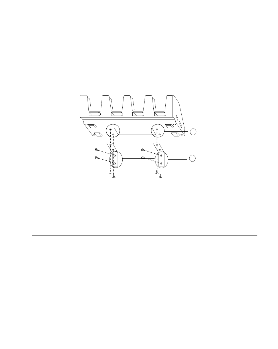
Wall Mounting the CCM
The CCM 38/6860 can be table or wall mounted.
To wall mount the CCM:
1. Attach the wall-mounting brackets to the bottom of the CCM using the four crosshead machine screws provided, as shown in Figure 2-11:
Attach Bracket
1
to CCM
with 2 Screws
Attach Bracket
2
to Wall
with Appropriate
Hardware
Figure 2-11. Wall Mounting the CCM
2. Position the CCM with attached brackets on the wall.
3. Insert the appropriate wall-mounting hardware into the bracket holes as shown in
Figure 2-11 and secure.
Note:Appropriate wall-mounting hardware to be provided by customer.
2-11
Page 31

Series 68XX Product Reference Guide
Coupling CCMs
Up to four 38/6860 CCMs can be coupled together for table or wall mounting, with power
provided by a single power supply attached to the left-most CCM. To couple two or more
CCMs for table or wall mounting:
1. Verify that add-on 3861-101 kit contains the following parts:
s 1 CCM
s 1 coupling bracket
s 6 cross-head screws
s 2 flat-head screws
2. On the add-on (or right-hand) CCM, use 3/16-inch driver to remove the jack screws
securing the communications port, ONE A T A TIME, and replace them with the flathead screws.
Note:Be sure to remove the jack screws one at a time; otherwise, the
connector will fall into the housing.
3. Mate the power port on the right side of the first cradle with the power port on the
left hand side of the second cradle.
4. Place the coupler between the CCMs, aligning the holes in the coupler to the holes
in the CCM’s base (Figure 2-12).
5. Install 6 cross-head screws through the coupler into the CCMs and tighten.
6. If you wish to wall mount the coupled CCMs, proceed as directed in W all Mounting
the CCM.
Screws
Coupling
2-12
Screws
Figure 2-12. Coupling Two CCMs
Page 32

Hardware Setup
Connecting Power to the 38/6860 CCM
Only the power connection is required for charging batteries in the CCM.
1. Install the power supply.
a. Attach the power supply to the left side of the CCM as shown in Figure 2-13
using two cross-head screws.
b. Connect the power supply plug to an AC wall outlet.
2. When the CCM is connected to power, all the LEDs flash at the same time for 3
seconds, flash once from left to right, and turn on for 3 seconds before going out.
Power Supply
Insert Screw
Insert Screw
+-
LEDs
+-
Null Modem Cable
Figure 2-13. Connecting the 38/6860 CCM for
Charging and Communications
CCM
2-13
Page 33

Series 68XX Product Reference Guide
Connecting the CCM for Serial Communications
Note:Both the communications cables and the power supply connection are
required for performing communications through the CCM.
1. Turn off the PC.
2. Plug the RS-232 null modem cable’ s DB-25 connector in the cradle’ s communication
port.
3. Connect the cable’s other connector to the host computer’s serial (COMM) port.
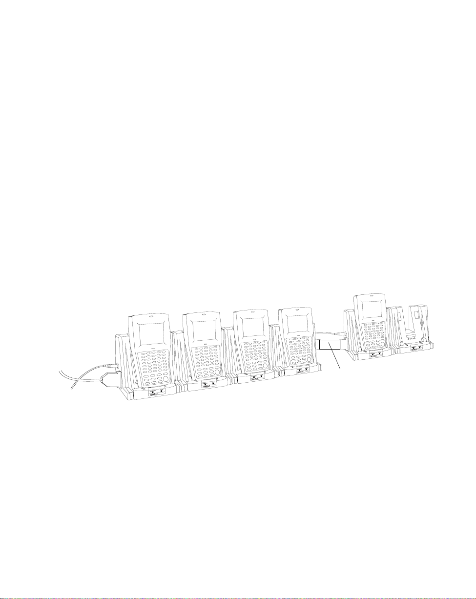
Daisy-Chaining Two or More CCMs
Up to twenty-four 38/6860 CCMs can be daisy-chained together for charging and
communications. To daisy chain two or more groups of four CCMs requires:
t one 25-pin, male-to-female, straight-through RS-232 cable per group of coupled
CCMs
and
t one power supply per group of coupled CCMs.
Depending on how close together you place the CCMs, the cables can be from 1-foot to 10feet long.
One Power Supply
and RS-232 Cable
per Group of
Coupled CCMs
(a “Group” Can
Number from
1 to 4 CCMs)
2-14
Figure 2-14. Daisy-Chaining Multiple 38/6860 CCMs
First
Coupled
Group
RS-232
Cable
Second
Coupled
Group
Page 34

Hardware Setup
To chain the CCMs:
1. Couple the CCMs as directed in the section Coupling CCMs.
2. In the first coupled section, connect the serial cable to the left-most CCM.
3. Connect the RS-232 cable’s (male or female) DB-25 connector in the serial port of
the right-most CCM in the first coupling.
4. Connect the (male or female) DB-25 in the serial port of the left-most CCM in the
second coupling.
5. Connect the power supplies for each coupled section as directed in Connecting
Power to the 38/6860 CCM.
2-15
Page 35

Series 68XX Product Reference Guide
The PC Adapter
The PC Adapter works with the Printer Interface Module (PIM). With this arrangement, you
can perform these tasks:
t Communicate to and from the PC without a 6860, 6865, or 6866 cradle
t Charge the NiCd battery pack in the terminal without a cradle.
Parts of the PC Adapter
The parts of the PC adapter are shown in Figure 2-15 and described below.
PIM
PC Adapter
DB-9 Connector
RS-232
Pin Port
Power Supply Port
Battery Charge
Indicator LED
Figure 2-15. Parts of the PC Adapter
t The Battery Charge Indicator LED flashes when the terminal power is turned on and
while the terminal's NiCd battery pack is being charged.
Note:When power to the PC Adapter is turned on, NiCd battery charging
begins automatically and continues for 7 hours.
The LED flashes once when the terminal is turned on. It remains steady while the
terminal is powered and blinks slowly during downloading.
t The RS-232 25-pin port is used to attach a null modem cable that connects to a PC
or other RS-232 device. See Appendix A for null modem pin-outs.
t The DB-9 connector is used to attach the PIM’s DB-9 connector.
t The power supply port is used to attach the 15-Volt power supply.
2-16
Page 36

Hardware Setup
Connecting the PC Adapter to 68XX and Serial Device
To set up the PC Adapter (refer to Figure 2-16):
PIM’s Optical
Connector
PIM
Power Supply
DB-25RS-232 Cable
Connector
PC
Adapter
Power
Supply
Port
DB-9 Port
Figure 2-16. Setting Up the PC Adapter
1. Turn the PC and terminal OFF.
2. Plug the PIM’s DB-9 connector in the PC Adapter’s DB-9 port.
3. Attach the PIM’s optical connector to the 68XX’s port by inserting the clips on the
connector in the slots on either side of the port (see Figure 2-17).
PIM
Optical Connector
68XX’s
Optical
Port
Slots
Clips
PIM Cable
Figure 2-17. Attaching the PIM’s Optical Connector
2-17
Page 37

Series 68XX Product Reference Guide
4. Connect the RS-232 cable’s DB-25 connector in the PC Adapter’s RS-232 port.
5. Plug the other end of the RS-232 cable in the RS-232 device (e.g., host PC).
6. Plug the jack end of the 16-Volt power supply into the power supply port.
7. Plug the 15-Volt power supply’s cube into an electrical outlet.
The Battery Charge Indicator LED flashes when the 68XX is powered on.
2-18
Page 38

Chapter 3
Batch and Spectrum One Terminal Setup
Introduction
Before using a Series 6800 terminal, perform the following procedures:
t Install the battery (refer to Chapter 6, Maintaining the Series 68XX)
t Charge the battery (refer to Chapter 6, Maintaining the Series 68XX)
t Load the system files and application(s).
Programs are stored in the terminal’ s nonvolatile memory (NVM), also called the application
EEPROM.
Hardware Requirements
The following equipment is required to initialize a batch or a Spectrum One radio terminal:
t 6800 or 6810 terminal
t One or more 38/6860 or 38/6865 cradles, or 38/6866 CCM
OR
t PC adapter with Printer Interface Module (PIM)
t A straight-through RS-232 null modem cable with male DB-25 connector at one end
and female DB-25 connector at the other end
t Power Supply
t Host Computer
3-1
Page 39

Series 6800 Product Reference Guide
Refer to Chapter 2, Hardware Setup, for instructions on setting up the cradles or PC Adapter
for communications.
Communications
For terminals being used in a direct communications (batch) environment or a Spectrum One
network environment, applications are transferred from a host computer to the terminal:
t over a communications line using a null modem connected to the cradle
OR
t through the PC Adapter.
The procedure uses the SENDHEX command on the host computer and the Program Loader
function (from Command Mode) on the terminal.
Note: For details on the SENDHEX command, refer to the Series 3000
Application Programmer's Manual.
Other software may be used in place of SENDHEX.
3-2
Page 40

Batch and Spectrum One Terminal Setup
Loading the Program
To download the program, initiate the communications software on the host computer and
terminal as described in the following sections.
Note: Communications parameters specified on the host and the terminal
must match. These parameters typically are:
38400 bps
7-bit parity
Odd parity
Xon/Xoff ßow control
To program the EEPROM, the terminal must be connected to the
host through a cradle, 6860 CCM, or PC Adapter with PIM.
Initiate Host Communications Software
Note: To cancel communications at any time during the session, press
CLEAR on the terminal. The session stops immediately.
1. Power on the host computer.
2. Start the communications program.
3. Enter the SENDHEX command.
sendhex pgmname 38400 com2
where:
SENDHEX is the command
pgmname is the application being loaded (.hex extension is optional)
parameters Communications parameters follow the program name.
Parameters include baud rate, communications port, data
bits, parity, and flow control. To accept the default
parameters, do not enter a value.
In the example, the baud rate is set to 38400 bps and the communications port to
COM2. The default values are accepted for the remaining parameters.
3-3
Page 41

Series 6800 Product Reference Guide
Note: Versions of SENDHEX earlier than 3.0 do not support flow control.
If you use an earlier version and encounter communication errors, use
a lower baud rate.
4. SENDHEX displays the prompt:
Press <Enter> to begin communications.
5. Do NOT press <ENTER> yet. Before starting communications (refer to Starting
Communications), set up the terminal as directed in Initiate Terminal
Communications.
Initiate T erminal Communications
1. Boot the terminal to command mode. Refer to Chapter 5, Operating the Series
68XX, for a list of the boot to command mode sequences.
The terminal displays the following:
COMMAND MODE
Select function
Self test
2. Scroll through Command Mode options using UpArrow or DownArrow until
"Program loader" is displayed. Press <ENTER>.
3. The terminal displays:
Program loader
WARNING: EEPROM
WILL BE ERASED
CONTINUE? <ENT>
Before loading the new application, erase the NVM’s original contents.
Note: To cancel this operation, press <CLEAR>.
4. Press <ENTER> to erase the EEPROM.
Wait while the EEPROM is erased. When complete, the program prompts for the
communications parameters.
3-4
Page 42

Batch and Spectrum One Terminal Setup
5. Baud Rate.The terminal displays:
Comm Parameters
Baud
4 9600
Scroll through the list using UpArrow or DownArrow. When the correct rate is
displayed (38400 is recommended), press <ENTER>.
6. Data Bits. The terminal displays:
Comm Parameters
Data Bits
7
Press <7> (recommended) or <8> to specify data bits, or scroll through the list using
UpArrow and DownArrow. Press <ENTER> when the correct value is displayed.
Note: If 8 data bits is selected, the program selects "No parity" and skips
the next step.
7. Parity. If 7 data bits is selected, the terminal displays:
Comm Parameters
Parity
Odd
Press the first letter of a parity option (Even, Odd, None, Space, or Mark), or scroll
using UpArrow and DownArrow and press <ENTER> when the correct value is
displayed.
8. Flow Control. The terminal displays:
Comm Parameters
Flow Control
None
Press the first letter of a flow control option (None, Xon/Xoff, or RTS/CTS), or scroll
using UpArrow or DownArrow and press <ENTER> when the correct value is
displayed.
3-5
Page 43

Series 6800 Product Reference Guide
Starting Communications
1. The terminal is ready to receive the program from the host PC and displays:
Comm Parameters
Start? <ENT>
2. Press <ENTER> on the terminal.
3. Press <ENTER> on the host computer. SENDHEX begins transmitting the program
image. When communications are established, the terminal displays:
Program loader
Receiving: XXXX
During program loading, the display shows the program segment address being
transferred (XXXX).
4. When the transmission is complete, the terminal displays:
Program loader
Status 0000
A status of 0000 (all zeros) indicates a successful transfer. Other status values
indicate an error. These values are provided in Appendix B, Communications Status
Codes.
If you received an error, press <Clear> on the terminal to return to the Command
Mode main menu.
Ending Communications
To return to the Command Mode main menu:
1. Press <Clear> on the terminal.
2. Power down the terminal.
3. Detach any cables connected to the terminal.
4. Reboot the terminal using the appropriate cold boot sequence described in Chapter
5, Operating the Series 68XX, in the section Booting a Series 68XX.
3-6
Page 44

Chapter 4
Spectrum24 RF Terminal Setup
Spectrum24 T erminals
In Spectrum24 terminals, wireless connectivity is accomplished using standard
communications protocols. Because they are standard, the protocols are generalized and take
up considerably more space on the terminal’s NVM than is required for Spectrum One®
terminals. Because there is less space available in NVM for application files, the terminal
operates with an additional megabyte of non-volatile memory or flash disk. This extra
memory is used to reduce not only the boot times but also the time and resources required to
load applications into the terminal. The flash disk also offers the possibility of running
multiple applications from the same terminal (refer to the section Multiple Applications on
the Same T erminal for more information). W ith version 3.03 or later of the system software
(LWP.HEX), the terminal can also run diagnostic tools.
Accessing the Flash Disk
The flash disk is accessed through a driver, FLASHDSK.SYS, which makes the flash disk
appear to a program as another disk drive (E:). The drive has characteristics of fast reading
but slow writing (e.g., even for the smallest files, the write process takes 3-4 seconds). These
characteristics make it ideal for files that are written once, accessed often, and seldom
updated.
We recommend that you use the flash disk (E:) mainly for application and configuration file
storage. It is important to note that because of the slow writing time (3-4 seconds), writing
files during a power interruption (low battery, dead battery, suspend, power off, or power
failure) could corrupt the disk. Be sure to only write data to the disk with the terminal
connected to external power or with the battery fully charged to avoid problems. To avoid
overwriting the flash disk by mistake, the flash disk is set to read-only mode for normal
operation.
4-1
Page 45

Series 6800 Product Reference Guide
Standard Spectrum24 Software
The 6840 comes with the system software installed, including:
t Spectrum24 radio drivers
t TCP/IP software
t configuration files
t various utilities.
A BIOS of version 3.08 or later is required.
The default files cover most expected installations/initializations with minor changes as
detailed in this chapter.
If your requirements are more advanced, refer to the SLASAP.COM documentation for more
information on the Spectrum24 RF network, SLAODI.COM, the Symbol-provided ODI
driver, and the configuration file setups required for various platforms.
Boot Options & Internet Addressing
Each 6840 requires a unique internet address (IP address), allowing messages it sends and
receives to be correctly routed over networks conforming to the TCP/IP protocol standards.
These addresses can be administered and entered manually , or administered and allocated by
a server on the network.
By default, the 6840 uses NOBOOT (manual entry) to define the IP address. To set the IP
address, use the CFG24 utility described later in this chapter in the section Initializing the
Series.
T wo protocols are defined for the IP address allocation on the network: BOOTP and DHCP.
T o allocate IP addresses through a BOOTP or DHCP server, you must change the boot option
in the configurator using the Boot Mode parameter.
4-2
Page 46

Spectrum24 RF Terminal Setup
Initializing the Series
To initialize a 6840 which has LWP.HEX version 3.03 or greater loaded:
Note: This section covers specific settings required on first booting the 6840
out of the box. For a complete review of the CFG24 screens, refer to
Appendix E, Spectrum24 Utilities.
1. Insert a charged battery in the 6840. Refer to Chapter 6 for instructions on charging
and installing a battery.
2. Cold boot the 6840.
For the 46-key 6840:
s Press and hold <A + B + D>.
s Press and release PWR.
s Release <A + B + D>.
3. The 6840 loads software, then brings up the Spectrum24 Configurator (CFG24)
menu, shown in Figure 4-1.
Note: CFG24 comes up automatically after the first initialization out of the
box. On subsequent initializations, type CFG24 at the DOS prompt
to bring up the configurator.
4-3
Page 47

Series 6800 Product Reference Guide
CONFIGURATOR 1.XX
View config params
Net Id
Subnet Mask
Default Router
Terminal IP Address
Diversity
Terminal Sleep Mode
Boot Mode
Power Management
Exit
áâ, Clear, Enter
Figure 4-1. CFG24 Main Menu
On the 6840 screen, the top and bottom lines of the menu are displayed, and the
remaining lines are viewed by scrolling. In this menu, pressing <CLEAR> has the
same effect as selecting Exit.
4. The 6840 initially is set to NOBOOT mode. T o configure the terminal for operation,
set up the parameters provided in T able 4-1 (the procedures are detailed in the steps
below).
Table 4-1. Spectrum24 Configuration Parameters
Net Id The Net Id identifies the radio network and differentiates
between different radio networks. All equipment on one
network must use the same Net Id.
Set to the same value specified for the Spectrum24 Access Points
(APs).
Boot Mode The boot mode indicates the source of the terminal’s IP address.
If this value is set to “Manual entry”, you must enter a terminal
IP address through CFG24.
4-4
Page 48

Spectrum24 RF Terminal Setup
Table 4-1. Spectrum24 Configuration Parameters (Continued)
Terminal IP Address Required if you are not using a boot server to allocate IP
addresses (BOOTP or DHCP).
Set as advised by your LAN administrator.
Note: Take care entering this value! The IP address must be
unique in the network or communications will be
unpredictable.
Subnet Mask Set as advised by your LAN administrator.
Note: If you change boot mode, the value set by a server
overrides this value.
Default Router The default router is the address of the node where all packets
destined for remote networks will be sent.
Set as advised by your LAN administrator.
Note: If you change boot mode, the value set by a server
overrides this value.
Diversity Determines whether the radio firmware attempts to use one or
two antenna ports for communications. It is important to match
this setting with the actual number of antennas in use.
If set to “Y es”, the radio firmware attempts to use both antenna
ports for communications.
The 6840 has one antenna. Set to “No”.
Terminal Sleep Mode Determines whether radio is powered off after the terminal
enters sleep mode due to inactivity. Refer to Appendix E for
more information.
The default value is “On”.
Power Management If power management is set to PSP, the radio powers up only
when there is traffic on the network. If it is set to CAM, the
radio is always ready to receive. Use the PSP setting to save
battery life.
The default value is “PSP”.
a. To view the 6840’s default parameters, select VIEW CONFIG PARAMS (Figure
4-2).
4-5
Page 49

Series 6800 Product Reference Guide
This screen is for display only; it is not a data entry screen. Use it to review the
terminal’s IEEE (or MAC) address, IP address, and Net Id. Press <CLEAR> or
<ENTER> to return to the main menu.
VIEW CONFIG PARAMS
Terminal IEEE addr
00:a0:f8:00:02:b8
Terminal IP Address
157.235.93.186
Net Id = 150
áâ, Clear, Enter
Figure 4-2. View Configuration
Parameters Screen
b. To change the Net Id, select Net Id from the CFG24 Menu. The Net Id screen
(Figure 4-3) is displayed.
NET ID
Enter Net Id(hex):
150
4-6
BkSp, Clear, Enter
Figure 4-3. Net Id Screen
To change the current Net Id value, backspace over the current value and type a
new value, in hexadecimal format, in the range 101 to 1FE. Alphabetical hex
values can appear in upper or lower case. The default value is 101.
Press <ENTER> to effect the change. Press <CLEAR> to exit without changes.
Page 50

Spectrum24 RF Terminal Setup
c. Select Subnet Mask from the main configuration menu. The Subnet Mask screen
(Figure 4-4) is displayed.
SUBNET MASK
Enter Subnet Mask:
255.255.255.0
Bksp, Clear, Enter
Figure 4-4. Subnet Mask Screen
T o change the current Subnet Mask setting, backspace over the current value and
type a new value, in decimal form. Each part of the four-part address must be in
the range 0 to 255. The default value is 255.0.0.0.
Press <ENTER> to effect the change. Press <CLEAR> to exit without changes.
d. Select Default Router from the main configuration menu. The Default Router
screen (Figure 4-5) is displayed.
DEFAULT ROUTER
Enter Default Router
157.235.93.178
BkSp, Clear, Enter
Figure 4-5. Default Router Screen
To change the current Default Router setting, backspace over the current value
and type a new value, in decimal form. Each part of the four-part address must
be in the range 0 to 255. The default value is 0.0.0.0.
Press <ENTER> to effect the change. Press <CLEAR> to exit without changes.
4-7
Page 51

Series 6800 Product Reference Guide
e. Select Terminal IP Address from the main configuration menu. The Terminal IP
Address screen (Figure 4-6) is displayed.
TERMINAL IP ADDRESS
Enter IP address:
157.235.93.186
BkSp, Clear, Enter
Figure 4-6. Terminal IP Address Screen
T o change the current Terminal IP Address, backspace over the current value and
type a new value in decimal form. Each part of the four-part address must be in
the range 0 to 255. The default value is 0.0.0.0.
Press <ENTER> to effect the change. Press <CLEAR> to exit without changes.
f. Select Diversity from the main configuration menu. The Diversity screen (Figure
4-7) is displayed.
DIVERSITY
2 antennas (Yes/No)
Yes
4-8
áâ, Clear, Enter
Figure 4-7. Diversity Screen
T o change the current Diversity setting, use the cursor keys to toggle between
áâ
the settings “Yes” and “No”. For the 6840, set Diversity to “Yes”.
Press <ENTER> to effect the change. Press <CLEAR> to exit without changes.
Page 52

Spectrum24 RF Terminal Setup
áâ
g. Select Terminal Sleep Mode from the main configuration menu. The Terminal
Sleep Mode screen (Figure 4-8) is displayed.
TERMINAL SLEEP MODE
Radio state:
On
áâ, Clear, Enter
Figure 4-8. Terminal Sleep Mode Screen
To change the current Terminal Sleep Mode, use the cursor keys to toggle
áâ
between the “On” and “Off” settings. The default setting is “On”.
Press <ENTER> to effect the change. Press <CLEAR> to exit without changes.
h. Select Boot Mode from the main configuration menu. The Boot Mode screen
(Figure 4-9) is displayed.
BOOT MODE
IP address from:
Manual entry
áâ, Clear, Enter
Figure 4-9. Boot Mode Screen
To change the current boot mode, use the keys to toggle among the three
settings: “Manual entry”, “BOOTP”, and “DHCP”. Refer to Appendix E for a
complete explanation of the three boot modes.
Press <ENTER> to effect the change. Press <CLEAR> to exit without changes.
4-9
Page 53

Series 6800 Product Reference Guide
i. Select Power Management from the main configuration menu. The Power
Management screen (Figure 4-10) is displayed.
POWER MANAGEMENT
Radio Power Mode
PSP
áâ, Clear, Enter
Figure 4-10. Power Management Screen
To change the current power management mode, use the keys to toggle
áâ
between the settings “PSP” and “CAM”. The default setting is “PSP”.
Press <ENTER> to effect the change. Press <CLEAR> to exit without changes.
5. When all of your changes are made, press <CLEAR> to return to the main
configuration menu.
6. Select Exit from the main configuration menu and press <ENTER> to exit the
configurator.
The 6840 displays the message:
...updating config data
and proceeds with the initialization which writes the configuration values to a
R/W non-volatile section of radio flash memory.
4-10
Page 54

Spectrum24 RF Terminal Setup
Initiating Network Connection
As the initialization continues, the terminal attempts to associate with the Spectrum24 AP
using the default or newly entered Net Id.
Series 684X Association with AP Not Successful
If the 6840 is unable to associate with the AP (the Net Id is wrong or forgotten), it displays
the message:
STAT24 Ver 1.XX
NOT Associated
for a few seconds. A second message follows:
Terminal cannot associate with AP. You’re
out of range or not configured. Ctrl+C to end
or other key to retry. Strike any key when
ready.....
The 6840 continues trying to connect until the attempt is cancelled.
1. Press <Ctrl + C> to end the attempt. The 6840 displays the message:
Halt Batch process Y/N?
2. Type Y to exit to the DOS prompt (D:).
3. At the DOS prompt, type CFG24 and press <ENTER> to initiate the Configurator
and bring up the Configurator screen.
4. V erify the Net Id with the LAN administrator to ensure you are entering the correct
value.
5. V erify other parameters and proceed as directed in the section Initializing the Series,
beginning with step 4a.
Series 684X Association with AP Successful
If the association is successful, the terminal begins operating using the software files loaded
on the flash disk.
On first initialization, you probably don’t have applications loaded. Proceed with loading the
applications as directed in Installing Application Software on Flash Disk. On subsequent
initializations, if only one application is loaded, that application is displayed automatically.
If you loaded multiple applications, an application selection menu is displayed early in the
initialization process. Select the application to load for the current session and proceed.
4-11
Page 55

Series 6800 Product Reference Guide
Installing Application Software on Flash Disk
Note: LWP.HEX version 3.03 or greater is required on the 6840 for this
process. If you are not sure of the terminal’s hex version, boot
(initialize) the 6840. The hex version is displayed for approximately 5
seconds during the initialization process.
Installing application software on the 6840 flash disk includes downloading a HEX file to the
6840, using SENDHEX on the PC and a batch file (_L.BAT) that runs Program Loader on
the terminal, then re-initializing the terminal. On the initial boot after a software download,
the 6840 copies the software files on to the flash disk, and remembers that the copy occurred,
ensuring that it is not repeated each time the WWC is booted.
The hardware required for performing the download includes:
t 6840 terminal
t configuration cradle (38/6860, 38/6865, or 38/6866)
t DOS PC
t RS-232 serial null modem cable
Initiate Host Communications on the PC
To update the hex image:
1. Power on the host computer.
2. On the PC, change to the directory where the application’ s hex file is stored and type
the following command at a DOS prompt:
SENDHEX <file name> 384 [1|2]<ENTER>
4-12
Page 56

Spectrum24 RF Terminal Setup
where:
SENDHEX is the command
<file name> is the hex file for the application being loaded. There may be other
application hex files which load other software (e.g., STEP version 2.6.0 or
greater, or TelNet Clients 3.0 or greater) to the flash disk.
Note: Be sure to use applications that are flash-disk enabled.
38400 is the baud rate.
[1|2] sets the host communications port the cradle is attached to.
The following message is displayed:
Press <ENTER> when remote is ready. ESC to abort...
3. Do NOT press <ENTER> yet. Set up the 6840 using the _L.BAT utility as directed
in the section Running _L.BAT.
Running _L.BAT
1. Place the 6840 in a configuration cradle.
2. Power the terminal on.
3. At a DOS prompt on the 6840, type _L<ENTER> using the keystrokes listed below.
For the 46-key 6840:
<SHF><FUNC><G><L><ENTER>
4. The terminal boots and displays the message:
Symbol Technologies
NVM Loader 2.X-XX
Connecting to Host
5. Press <ENTER> on the host PC.
6. The batch file runs Program Loader with the communications parameters set to
38,400 bps, 7 data bits, odd parity, and no flow control. The 6840 displays the
screen:
Symbol Technologies
NVM Loader 2.09-XX
4-13
Page 57

Series 6800 Product Reference Guide
Address: XXXX
7. When the hex download is complete, the 6840 automatically reinitializes (warm
boots) and copies the files in the software package to the flash disk. If the 6840 does
not reinitialize, re-initialize the 6840 using the following key sequence:
Note: The 6840 must be re-initialized to copy the software to the flash disk.
For the 46-key 6840:
s Press and hold the 4 and 5 keys.
s Press and release PWR.
s Release the 4 and 5 keys.
Note: If you get a timeout message at any time during the procedure, press
<ENTER> to return to the screen.
8. The software is copied on to the flash disk.
9. Proceed with initializing the network connection as described in the section Initiating
Network Connection.
Note: If you downloaded multiple applications, a “select” screen appears
before the 6840 attempts to associate with an AP, requesting that you
select an application.
4-14
Page 58

Spectrum24 RF Terminal Setup
Updating System Software on Flash Disk
Updating the LWP hex image means loading the new system files on the flash disk using the
SENDHEX utility on a PC. It is possible to perform this update on multiple terminals in a
cradle at one time, with each terminal running Program Loader from Command Mode.
Note: The 6840 is shipped with the LWP hex file installed. Use this
procedure ONLY:
• to load a new version of LWP greater than 3.03
• if you experience serious difficulties
• if you are so directed by Symbol’s Technical Support staff.
Option: Using _L.BAT to Update System Software
If the 6840 terminal contains a LWP hex file of version 3.03, you can follow the instructions
for installing application software on the flash disk using _L.BAT through step 6, when the
terminal is reinitialized. Proceed to step 6 of this procedure at that point.
Note: Be sure, when entering the SENDHEX command on the PC, to issue
the command from the directory where the hex file (LWP.HEX) is
stored.
Initiate Host Communications on the PC
To update the system software:
1. Power on the host computer.
2. On the PC, change to the directory where the system hex file (LWP.HEX) is stored
and type the following command at a DOS prompt:
SENDHEX LWP 384 [1|2] <ENTER>
4-15
Page 59

Series 6800 Product Reference Guide
â
where:
SENDHEX is the command.
LWP is the hex file being loaded. LWP.HEX is the hex file specifically for
the system files. There may be other hex files which load other
software, such as applications, to the flash disk.
384 is the baud rate (38,400 bps).
[1|2] sets the host’s communication port the cradle is connected to.
The following message is displayed:
Press <ENTER> when remote is ready. ESC to abort...
3. Do NOT press <ENTER> yet. Set up the terminal as described in Initiate Terminal
Communications.
Initiate T erminal Communications
1. Power off the 6840 and place it in the cradle.
2. Boot the 6840 to Command Mode.
For the 46-key 6840:
s Press and hold <F + I >.
s Press and release PWR.
s Release <F + I >.
The terminal displays the function selector screen:
COMMAND MODE
Select function
Self Test
3. Scroll through the Command Mode options using or until “Program loader”
á
is displayed. Press <ENTER>.
4-16
Page 60

Spectrum24 RF Terminal Setup
4. The 6840 displays:
Program loader
WARNING: EEPROM WILL
BE ERASED
CONTINUE?
<ENT>
Note: To cancel this operation, press <CLEAR>.
5. Press <ENTER> to erase the EEPROM.
Wait while the EEPROM is erased. When complete, the program prompts for the
communications parameters.
6. Set the parameters to 38,400 bps, 7 data bits, odd parity , and no flow control. Press
<ENTER>.
Start Communications
1. The 6840 displays:
Comm Parameters
Start? <ENT>
2. Press <ENTER> on the 6840.
3. The 6840 displays:
Comm Parameters
Receiving: XXXX
If the host is not ready or if the cable is not connected properly between the host PC
and the cradle, the 6840 displays:
Awaiting DSR
4. Press <ENTER> on the host PC to start the download. The 6840 displays:
Program loader
Status XXXX
4-17
Page 61

Series 6800 Product Reference Guide
5. When the transmission is complete, the 6840 displays:
Program loader
Status 0000
A status of 0000 (all zeroes) indicates a successful transfer. If the status is other than
0000, check the cable connections between the host PC and the cradle and repeat the
process. If the problem persists, contact the Symbol Support Center for assistance.
6. When the download is complete, the 6840 displays the following query:
LWP.HEX Ver X.XX
Loading system files
1. Reformat flash
2. Use flash as-is
Select [1,2]:
Caution
Reformatting the flash removes all system files and applications stored on
the flash disk.
Select 1, Reformat flash, ONLY if you have problems with the 6840’s oper -
ation. Select 2, Use flash as-is, to update the flash while retaining the existing
contents.
7. If you select 1, the 6840 displays the message:
Are You sure Y or N
8. Press Y to continue with the reformat or N to cancel and press <ENTER>.
The 6840 finishes reformatting (if requested), copies the files to the flash disk, and
executes them.
4-18
Page 62

Spectrum24 RF Terminal Setup
Compatibility Issues When Updating
While the order in which software packages are loaded is not important, we recommend
loading the system files, LWP.HEX, first, before loading any application files. You don’t have
to reload existing applications that conformed to previous standards for flash disk
applications. Loading just the system files allows the old applications to run with updated
system software.
Note: Some configuration changes may be required.
Complications: Naming Applications
In versions of LWP.HEX for flash disk terminals prior to version 3.03, parameters were
defined in NET.CFG to specify the applications that would run on the terminal. If only one
application was used and no applications were defined in NET.CFG, the system gave the
application the default name, APP. This can cause problems if you plan to add more
applications to terminals using version 3.03 HEX files.
With LWP.HEX 3.03, the application entries in NET.CFG are not longer required. The
system now decides which applications are installed on the terminal by scanning the flash
disk’s directories and files. If you had an original application with the default name APP, it
will show up in the application selection menu as APP. If you updated that old application
(e.g., created a version 3.03 HEX file of the application), the application selection menu will
contain both versions, one called APP and one by the “real” name (e.g., STEP).
Because of this potential problem, if ALL the software on the flash disk is being replaced in
the update, we recommend reformatting the flash disk using FLSHFMT . Reformatting deletes
ALL the files on the flash disk and eliminates this duplication.
Note: DO NOT run the FLSHFMT utility unless all the HEX files,
including LWP.HEX, are available to recreate the flash disk file
system.
Complications: System Parameters
In flash disk terminals with a LWP.HEX version prior to 3.03, some system parameters were
changeable only by editing NET.CFG (e.g., power management mode, boot mode, and
diversity). These parameters were not saved in the radio flash.
4-19
Page 63

Series 6800 Product Reference Guide
When the LWP.HEX is updated to 3.03, these values revert to the defaults. Be sure to check
them after LWP.HEX is installed. In particular, verify whether a BOOTP or DHCP server is
being used to allocate IP addresses. The default boot mode in version 3.03 is manual entry of
IP addresses. The terminal enters the configurator during the first terminal initialization after
the LWP.HEX upgrade, allowing you to check the settings.
Multiple Applications on the Same Terminal
The system files (from LWP.HEX) fill over 200 KB of the flash disk’s 1 MB. Current standard
applications such as STEP or TN clients require between 100 KB and 150 KB of flash disk.
This leaves ample space for installing more than one application on a single 6840. T erminals
have been configured to run as many as four applications, with a maximum of five
applications allowed.
Individual applications may require special terminal configurations that can only be set at
boot time, such as RAM disk size. The TN clients require configuring a minimum-size RAM
disk (<100 KB) because their limiting resource is program execution space. STEP , on the other
hand, uses the RAM disk to hold forms. Some STEP application implementations use forms
extensively and require a larger RAM disk (>100 KB). The application loaded last defines the
size of the RAM Disk for all applications on the flash disk.
Note: The system files contained in the LWP.HEX have the RAM disk
defined as 80 KB.
It is possible with multiple applications to have applications co-
existing on the terminal with conflicting memory requirements. If this
occurs, work out a compromise value that both applications can work
with before loading the files.
If multiple applications are installed on the 6840, a menu is presented during the initialization
process where you select the application to run for this session. Switching between
applications requires re-initializing the terminal and selecting an alternative application when
prompted. On warm boots, the terminal re-initializes and reenters the same application that
was selected before the re-initialization. On cold boots, if there are multiple applications
available, an application selection menu is presented.
4-20
Page 64

Chapter 5
Operating the Series 68XX
Overview
This chapter describes how to operate a Series 68XX, including:
t Powering the 68XX on and off
t Booting the 68XX
t Adjusting the display contrast
t Entering data using the keyboard
t Entering data using the scanner
t Capturing signatures
t Communicating with a PC or printer
t Communicating on an RF network.
5-1
Page 65

Series 68XX Product Reference Guide
Normal Power On Techniques
There are several ways to power on a terminal. Each way lets you resume at the same location
in the application where you left off.
Note: The Series 68XX terminals always check for enough battery power
for safe operation before they power on.
Removal From a Cradle
The terminal automatically powers on when it is removed from a cradle. While the terminal
is in the cradle, the battery is constantly being charged. If you remove the terminal from the
cradle but do not use it right away, press the PWR key to turn it off, or let it power off
automatically. Refer to the section Restoring Power After Automatic Shutdown.
Keyboard
Your terminal can be programmed to power on from the keyboard in one of two ways:
t Press the PWR key only.
t Press any key.
t If you press the PWR key while the terminal is in the cradle, the terminal powers on.
If you leave the terminal in the cradle and press PWR to turn the terminal off, it
appears to turn off; however, the terminal is on very low power.
See the your application guide or the Series 3000 Application Programmer's Guide for more
information.
Real-Time Clock
If the application program allows it, the terminal can be powered on by the real-time clock.
This lets the terminal perform unattended operations, such as an overnight communication
session.
Laser Trigger
If the application program allows, you can power on the terminal by pulling the laser trigger.
5-2
Page 66

Operating the Series 68XX
Restoring Power After Automatic Shutdo wn
The terminal shuts off if you don't use it for an amount of time set by your application. Press
the PWR key or press the trigger to restore power and return to your application.
Power Off
To perform a normal power off, press the PWR key or let the terminal shut down
automatically as programmed. See your application guide or the section Restoring Power
After Automatic Shutdown for more information. Consult your system administrator if you
are unable to power off the terminal.
Forced Power Off
If pressing the PWR key does not turn off the terminal, force the power off to reduce battery
drain and preserve your data.
To force power off, press and hold the PWR key for 15 seconds, until the terminal powers
down.
Restarting After a Forced Power Off
When a terminal is powered off because of software or hardware failure, use the following
methods to restart:
t Use the warm-boot procedure for a software failure.
t When a warm boot fails, use the cold-boot procedure.
t If a system software problem in the nonvolatile memory (NVM) occurs, see
Chapter 3, Batch and Spectrum One Terminal Setup.
Note: Do not use the PWR key to restart a terminal when it was forced off
due to defective system or application software in the NVM. Pressing
the PWR key causes the program to resume where it stopped, trying
to perform the same unsuccessful operation.
5-3
Page 67

Series 68XX Product Reference Guide
Booting a Series 68XX
Warm Boot
A warm boot resets the operating system while preserving the RAM disk.
To perform a warm boot:
1. Power off the Series 68XX.
2. Press and hold the 4 and 5 keys.
3. Press and release the PWR key.
4. Release the 4 and 5 keys.
The terminal displays configuration information, copyright, RAM size, and expanded
memory RAM size. Other information displayed depends on the operating system, installed
device drivers, and AUTOEXEC.BA T commands. If this warm-boot procedure fails to restart
the terminal, use the cold-boot procedure.
Cold Boot
A cold boot resets the BIOS and operating system; it erases and recreates the RAM disk. If
the cold-boot procedure fails to restart the terminal, see Chapter 7, Error Recovery and
Troubleshooting.
Caution
This procedure permanently erases all data and software in the terminal unless they reside in NVM. Contents of RAM are lost.
To perform a system cold boot:
1. Power off the Series 68XX.
2. Press and hold the A, B, and D keys.
3. Press and release the PWR key.
4. Release the A, B, and D keys.
The terminal displays version information, copyright, RAM size, and installed expanded
memory RAM size. Other information displayed depends on the operating system, installed
device drivers, and AUTOEXEC.BAT commands.
5-4
Page 68

Operating the Series 68XX
Cold-Boot Failure
During a cold boot, the system briefly displays a status line for each driver as it loads in the
format:
0: Driver #.##
The line shows a status value, usually 0, followed by the name and version number of the
driver. If the system halts at one of these lines and displays a status value other than 0, the
displayed device driver failed to load properly.
If such a failure occurs, try cold booting the terminal again. If this does not solve the problem,
call the Symbol Support Center.
More troubleshooting information is provided in the publications listed in Related
Documentation at the beginning of this manual.
Boot to Command Mode
Command Mode provides functions for:
t Running the Self-Test program to verify that the hardware is operating properly
(refer to Chapter 7, Error Recovery and Troubleshooting).
t Performing a Memory Transfer to upload data from a terminal to a host system
(refer to Chapter 7, Error Recovery and Troubleshooting).
t Performing a Program Download to transfer an application from the host to a
terminal (refer to Chapter 3, Batch and Spectrum One Terminal Setup).
To boot to Command Mode:
1. Power the Series 68XX off.
2. Press and hold down the F and I keys.
3. Press and release the PWR key.
4. Release the F and I keys.
5-5
Page 69

Series 68XX Product Reference Guide
Adjusting the Screen Contrast
Display Contrast
The screen’s contrast is adjustable to eight levels, making the display more readable in
different lighting conditions, and at various temperatures.
t To reduce (lighten) display contrast, press FUNC X.
t To increase (darken) display contrast, press FUNC Y.
Back Lighting
The backlight illuminates the display in dimly lit areas.
To turn the back light on or off, press FUNC then L, or use the key sequence listed in your
application guide. The back light turns off automatically when the terminal is powered off or
when the terminal has not been used for an amount of time set by the application. See the
application guide for more information.
Entering Data
The Keyboard
The keyboard is used for entering data and issuing commands to the terminal. The keys on
the keyboard are distinguished as modifier keys and character keys. Because terminal
keyboards have fewer keys than PC keyboards, each character key can produce more than
the usual one or two characters. The modifier keys, SHF (Shift), CTL, and FUNC, used
individually or in combination, determine which character or special function the character
keys produce.
Because the keyboard is programmable, your terminal may not work as described here. For
more information and illustrations of other keyboard states, see the Series 3000 Application
Programmer's Guide and your application guide.
Using the Keyboard
Except for during boot operations, the terminal expects the operator to press keys one at a
time. If the terminal has been programmed for it (ERR3000 is loaded), and if two or more
keys are pressed simultaneously , the terminal indicates a Double-Key or Too Many Key error.
5-6
Page 70

Operating the Series 68XX
The keyboard also has an optionally configurable auto-repeat function. If the application
allows, a character repeats as long as the key is held down. If the key is pressed immediately
following a modifier key, the modifier sequence affects only the first occurrence of the
character key.
Modifier Keys
The Shift, Alpha, Function, and Control keys are modifier keys. When pressed individually
or in certain combinations, these keys change the keyboard state and possibly the character
produced by the character key subsequently pressed. Refer to Table 5-1 for a list of the
68XX’s special keys.
For example, pressing <Func> followed by <Ctrl> produces Alt characters, with the same
effect as pressing the Alt key on a PC.
Keyboard Speed
If your application program allows it, the characters may be set to appear faster or slower.
Refer to the Series 3000 Application Programmer's Manual for more information.
Keyboard States
The keyboard states are listed below, in the order in which they take priority:
Unshifted
Shifted
Function
Control
Momentary and Locked States
Each keyboard state is either momentary or locked. A momentary state lasts for only the
following keystroke. A locked state lasts until the activator key is pressed again.
Only one momentary state can be active at a time. Momentary states always take priority
over locked states. If you press several momentary state keys in a row , the system changes to
the state of the last key pressed. For example, if you press SHF, then CTRL, the terminal
enters the CONTROL state.
The CTRL, SHF, and FUNC keys activate a momentary state. If you press a momentary state
key twice in a row, the system enters the state and then cancels it. For example, if you press
SHF, SHF, the terminal is shifted and then immediately unshifted.
When batteries are low , the cursor changes. See Keyboard State Cursor Formats in Table 5-2.
5-7
Page 71

Series 68XX Product Reference Guide
When an operator ends a momentary state (by toggling it off or by completing the key
sequence), the system returns the keyboard to the last active locked state.
Note: Pressing the FUNC key does not clear the last momentary state.
However, pressing another momentary key after FUNC clears the
FUNCTION state.
Table 5-1. Special Keys
Key Name Description
CTL (Control) Invokes the control command.
FUNC (Function) Invokes the function command for certain utilities,
such as turning on the back light.
s Press FUNC and the corresponding numeric key
to produce function keys F1 to F10.
s Press FUNC, then to scroll left and FUNC to
scroll right.
s Press FUNC then BKSP to enter a blank space.
5-8
BKSP (Backspace) Erases information entered on the display one
character at a time. Information erased this way
cannot be recovered. This key is also used to
produce a break by pressing CTL, BKSP.
PWR (Power) Turns the terminal on and off.
CLR (Clear) Partially or completely escapes from an application
level or screen. CLR also clears all data typed from
the display.
SHF (Shift) Accesses the shifted keyboard.
ENTER Places entered data into the terminal’s memory.
Move the cursor up, down. Press FUNC then to
scroll left; press FUNC then to scroll right.
Arrow key use depends on the application.
Page 72

Operating the Series 68XX
Keyboard Key Definitions
The standard tasks performed by the keys in their normal, unshifted state are shown in Figure
5-1 and listed in Table 5-1. For all other keyboard states, refer to Appendix B of the Series
3000 Application Programmer’s Reference Manual.
Figure 5-1. 46-Key Keyboard
=
5-9
Page 73

Series 68XX Product Reference Guide
Table 5-2. Cursor Indicators
Keyboard State Cursor Character
Unshifted
Shifted
Momentary Shifted
Momentary Unshifted
Control
Function
(inverted caret) (inverted solid caret)
(caret) (solid caret)
(up arrow) (solid up arrow)
(down arrow) (solid down arrow)
c
(underline c) (inverse c)
(underlined f) (inverse f)
f
Low Battery
5-10
Page 74

Operating the Series 68XX
Scanning
Before scanning can occur, the terminal must be running an application that supports bar
code scanning. The terminal must also be programmed to scan the type of bar code you want,
such as Universal Product Code (UPC) or Code 3 of 9. For information on scanning
applications and on programming the scanner, refer to the Series 3000 ADK.
Entering Data Using the Laser Scanner
1. Pull the trigger on the handle to power on the 68XX and laser scanner . The Scan LED
turns red if scanning is enabled and the laser is on.
2. Point the 68XX at a slight angle to the bar code and pull the trigger.
Figure 5-2. Scanning with the 68XX
3. Ensure that the scan beam crosses all bars and spaces on the bar code symbol, as
shown below. Do not hold the scanner directly over the bar code.
Wrong Right
Optimal scanning distance varies with bar code density and scanner optics, but more
combinations work within 4 to 10 inches.
4. If the decode is successful, the screen displays the code and the Scan LED flashes red.
The terminal may also beep.
5-11
Page 75

Series 68XX Product Reference Guide
Note: The procedure for your scanner may differ from the one given above.
Scanner use depends on the application.
Scanning Considerations
Usually, scanning is a simple matter of aim, scan, and decode, and a few quick trial efforts
master it simply and intuitively. However, two important considerations can optimize any
scanning technique — angle and range.
Angle
Scanning angle is important for promoting quick decodes. When laser beams reflect directly
back into the scanner from the bar code, this specular reflection can actually “blind” the
scanner.
To avoid this, scan the bar code so that the beam does not bounce directly back. But don’t
scan at too oblique an angle; the scanner needs to collect scattered reflections from the scan
to make a successful decode (refer to Figure 5-3). Practice quickly shows what tolerances to
work within.
5-12
Figure 5-3. Scanning Angle and Specular Reflection
Page 76

Operating the Series 68XX
Range
Any scanning device decodes well over a particular working range — minimum and
maximum distances from the bar code. This range varies according to bar code density and
scanning device optics.
Scanning within range brings quick and constant decodes; scanning too close or too far away
prevents decodes. You need to find the right working range for the bar codes you are
scanning. The best general advice is:
t Hold the scanner farther away for larger symbols.
t Hold the scanner closer for symbols with bars that are close together.
t Start scanning at a distance from the bar code, not from direct contact. If the bar
code does not readily decode, move the scanner in closer.
Practice quickly shows what distances to work within.
5-13
Page 77

Series 68XX Product Reference Guide
Communications
With a Host
To communicate with a host:
1. Set up the 38/6860 CCM, 38/6865 cradle, 38/6866 cradle, or the PC adapter as
described in Chapter 2, Hardware Setup.
2. If using a cradle, place the terminal in the CCM or cradle.
3. Start the communications program on the host and terminal.
With a Printer
To communicate with a printer, attach the 68XX to the Printer Interface Module:
1. Attach the PIM’s optical connector to the 68XX’s port by inserting the clips on the
connector in the slots on either side of the port.
PIM
Optical Connector
Clips
Slots
68XX’s
Port
Optical
Figure 5-4. Connecting the 68XX and the PIM
2. Plug the PIM’s DB-9 connector in the printer’s port.
3. Power the printer and 68XX on.
5-14
Page 78

Operating the Series 68XX
RF Network Communications
The PDT 6810 operates in a Symbol Spectrum One® RF network; the 6840 operates in a
Symbol Spectrum24® RF network.
The terminal’s Status LED indicates the state of the 6800’s connection to either of the RF
networks:
Off indicates that the radio is working and associated with an access
point (Spectrum24) or base station (Spectrum One).
Status LED indication of RF status presently not available
Flashes red once per
second
to indicate that the radio is out of range or not associated with
an access point or base station.
Status LED indication of RF status presently not available.
Refer to the network documentation for more information on operating the 68XX in the
specific RF environment.
5-15
Page 79

Series 68XX Product Reference Guide
5-16
Page 80

Chapter 6
Maintaining the Series 68XX
Batteries
The Series 68XX terminal is powered by a rechargeable nickel cadmium (NiCd) battery pack
or one 9-volt alkaline battery installed in the alkaline battery adapter. Fully charged, the
NiCd battery pack provides up to 8 hours of continuous operation.
The NiCd battery pack is recharged by:
t placing a 68XX with the battery installed in a 38/6860 CCM or in a 38/6865or 38/
38/6866 cradle for 7 hours, or
t by connecting the terminal to a PC Adapter, or
t by placing the battery pack in a spare battery charging slot on the 38/6860 or 38/
6865 for up to 7 hours.
Note: The terminal can be used while the battery is being charged in the
38/6860 CCM or connected to the PC Adapter.
Battery Life
Battery life is affected by many factors, including
t scanning
t radio communications
t very high or very low operating temperatures
t backlighting use
t battery age.
6-1
Page 81

Series 68XX Product Reference Guide
When to Replace or Recharge the Battery
The Series 68XX terminals provide two types of indicators to notify you when battery power
is running low: warning messages and modified cursors. These indicators may be changed or
disabled by an application.
t LOW BA TTERY - When the battery is low, the cursor changes as shown in Table 6-
1. If ERR300 is loaded, the message LOW BA TTERY also appears. At this level the
terminal continues to operate, but there is probably less than 1 hour of usable power
left.
t VERY LOW - When the power is very low, the DEAD BATTERY message appears
and the system powers off. Replace an alkaline battery or recharge a NiCd battery
before attempting to use the terminal. If the battery is not immediately recharged or
replaced, data may be lost.
Table 6-1. Cursor Indicators
Keyboard State Cursor Character
Unshifted
Shifted
Momentary Shifted
Momentary Unshifted
Control
Function
(inverted caret) (inverted solid caret)
(caret) (solid caret)
(up arrow) (solid up arrow)
(down arrow) (solid down arrow)
c
(underline c) (inverse c)
(underlined f) (inverse f)
f
Low Battery
Backup Batteries
T o prevent data loss during battery replacement, the terminal utilizes a supercap as a backup.
The supercap provides sufficient power to preserve memory contents for approximately 15
minutes while the primary battery is replaced. The supercap does not provide enough power
to operate the terminal. On receiving a low battery message, replace or recharge the primary
batteries immediately.
6-2
Page 82

Maintaining the Series 68XX
NiCd Battery Pack
Replacement Battery Packs
NiCd battery packs available from Symbol are listed below.
System P/N Battery Pack
Five-cell, 780 mAh 21-32801-01 NiCd rechargeable
Six-cell, 600 mAh IS Intrinsically safe NiCd
rechargeable battery pack
Note: The Series 3800 NiCd battery packs, 3872-103, 3872-105, and 3872-
115, cannot be used in the Series 6800 terminal.
Removing the NiCd Battery Pack
To remove the battery pack (refer to Figure 6-1):
1. Power the terminal off.
2. Press the battery release buttons on both sides of the handle (Figure 6-1).
Press release buttonPress release button
Figure 6-1. Releasing the Battery
6-3
Page 83

Series 68XX Product Reference Guide
3. Slide the battery pack out of the handle.
Battery Compartment
Battery Pack
Figure 6-2. Sliding Battery Pack Out of Battery Compartment
Caution
If you intend to store your terminal without the battery pack, ensure you
have stored any data and/or programs you wish to keep on another terminal,
a host computer, or another medium to avoid loss of data. The terminal
backup power source retains data for approximately 15 minutes after the
battery pack is removed, as long as the backup batteries remain in place.
6-4
Page 84

Maintaining the Series 68XX
Installing the NiCd Battery Pack
1. Orient the battery pack with the handle facing the 68XX’s scan window.
2. Slide the pack into the battery compartment while pressing the battery release
buttons.
3. Press the battery lock in to secure.
Orient
Figure 6-3. Inserting the NiCd Battery Pack in the Battery Compartment
Slide
Push to
Lock
6-5
Page 85

Series 68XX Product Reference Guide
Charging the NiCd Battery Pack
The NiCd battery pack automatically charges when the terminal is placed in a cradle or
connected to a PC Adapter. A full charge takes about 7 hours. We recommend that you
always keep the NiCd battery pack fully charged.
Battery Charging in the Terminal Using a Cradle
To charge a NiCD battery in the terminal, using the 38/6860, 38/6865, or 38/6866 cradle
(Figure 6-4):
1. Place the terminal in the cradle. The cradle charging light flashes when charging a
discharged battery and remains steady when trickle-charging a charged battery.
38/6860
38/6865
38/6866
Figure 6-4. Charging the Battery in the Cradle
2. Leave the terminal up to 7 hours to recharge a fully discharged battery.
6-6
Page 86

Maintaining the Series 68XX
Charging Battery Packs Outside the Terminal
Slots are provided in 38/6860 and 38/6865 cradles to charge spare battery packs outside the
terminal.
Place the battery pack to be charged in one of the battery slots in the cradle. The LED
indicator lamp under the battery slot in which the terminal was placed indicates the battery
is charging. (On the 38/6860 CCM, the spare-battery-charging indicator lamp is on the
right.) If the lamp is off, charging is not occurring. A blinking LED indicates fast charge; a
solid on LED means slow charge/ready. See the cradle documentation listed in Related
Publications for details.
Caution
The optional communications cradles are NOT certified for use in potentially hazardous environments. T o charge an intrinsically safe Series 68XX in a
cradle, remove the terminal from the potentially hazardous environment before charging.
Battery Charging with the PC Adapter
Refer to Chapter 2, Hardware Setup, for instructions on setting up the PC Adapter for
charging.
Battery charging begins automatically when power is supplied to the PC Adapter. Fully
charging a battery using the PC Adapter requires 7 hours.
Other Charging Options
You have the option of charging battery packs in the UBC 1000 or 2000 Charger. Refer to
the documentation for the charger for more information.
6-7
Page 87

Series 68XX Product Reference Guide
Battery Charging Tips
For maximum capacity and battery life, follow these helpful hints:
Do
t Charge at temperatures between 0°C and 38°C (32°F to 100°F); 21°C (70°F) is
preferred
t Recharge as soon as you see the “Low Battery” message
t Save your data and program on another terminal or another medium if you plan to
store your terminal without the primary battery pack
t Store batteries at room temperature of 21°C (70°F) or cooler
t Recharge the NiCd battery pack after storage.
Don't
t Store or recharge primary batteries at temperatures below 0°C (32°F) or above 38°C
(100°F)
t Judge a battery's charge level by measuring its voltage; voltage does not indicate
charge level.
6-8
Page 88

Maintaining the Series 68XX
Cleaning
Series 68XX terminals require a minimum amount of maintenance, and proper use and care
of the terminal will enable it to function accurately for a long time.
To clean a terminal, use a clean soft cloth dampened with water. Do not use abrasive paper,
cloth, or abrasive/corrosive cleaners. Wipe the entire terminal, except for the scanner
window, with the damp cloth, including the charging contacts.
Wipe the scanner window periodically with a lens tissue or other material suitable for
cleaning optical material such as eyeglasses.
Storage
If the terminal will not be used for a while, store it in a cool, dry place, away from dust. For
the best protection, repack the terminal in the original shipping container for storage.
Caution
If you remove the primary battery , the terminal maintains memory contents
for at least 15 minutes. T o prevent loss of programs and data, transmit them
to a host computer before removing the primary batteries for longer than 15
minutes.
When you remove the Series 68XX terminal from storage without the battery pack, reset the
real time clock. Refer to the Series 3000 Application Programmer’s Reference Manual or
Series 3000 Application Programmer’s Guide for specific instructions.
6-9
Page 89

Series 68XX Product Reference Guide
6-10
Page 90

Chapter 7
Error Recovery and Troubleshooting
This chapter provides information to assist in basic trouble analysis and correction,
including:
t Error messages
t Troubleshooting start-up failures
t Troubleshooting Spectrum24 terminal initialization failures
t Running the self test function
t Self test summaries
t Keyboard test
t Scanning problems
t Running memory transfer.
7-1
Page 91

Series 68XX Product Reference Guide
Error Messages
If ERR3000 is loaded in the system configuration, the terminal displays the following
messages to indicate error conditions that affect system performance. A message is usually
accompanied by one or more beeps, after which the system returns to its previous status.
The application can change the actual wording of the messages or disable messages. The
messages listed in Table 7-1 are representative. Refer to the Series 3000 Application
Programmer's Guide or your application guide for additional information.
Table 7-1. Error Messages
Message Explanation
Double Key Error Two or more keys were pressed at the same time.
Low Battery The battery pack should be recharged or replaced as soon as
possible.
Dead Battery Replace or recharge the battery pack immediately . This message
is programmable, so it may be worded differently. See your
application guide. After this message is displayed, the terminal
shuts itself off.
Power Fault The last terminal power off was caused by a terminal power
failure. Possible causes of a power fault include:
7-2
• the battery pack is removed with the terminal on.
• the terminal is dropped.
• the batteries lose power suddenly.
• the terminal displays a low battery power error message, and
you attempt to power the terminal on without recharging or
replacing the batteries.
Page 92

Error Recovery and Troubleshooting
Troubleshooting Guide
Table 7-2 lists some minor problems, causes, and actions to take. If you cannot resolve the
problem after checking this list, call the Symbol Support Center for assistance.
Table 7-2. Troubleshooting the 6800
Symptom Possible Cause Action
Display is blank. Battery pack is dead or
missing.
Terminal does not respond
when keys are pressed.
Time and date are incorrect. Real-time clock has
Application program was not
successfully downloaded.
malfunctioned or needs
setting.
Startup Failure
Problems are most frequently start-up failures. If cold booting the terminal does not start the
application successfully, either the application, the system software, or the system is
malfunctioning. If you can boot the system to Command Mode, try the following:
Replace or recharge battery
pack.
Repeat downloading.
Set time and date. See your
application guide.
t Use Program Loader to download a new version of the software to NVM. This
procedure is described in Chapter 3, Batch and Spectrum One T erminal Setup. After
downloading new software, warm boot the terminal as described in Chapter 5,
Operating the Series 68XX.
t Use Self Test to check whether system hardware is operational. The Self Test
procedure is described later in this chapter.
Boot Failure Messages
During a cold boot, the system briefly displays a status line for each driver as it loads, in the
format
0:Driver #.##
The line shows a status value, usually 0, followed by the name and version number of the
driver. If the system halts at one of these lines and displays a status value other than 0, the
displayed driver did not load properly.
7-3
Page 93

Series 68XX Product Reference Guide
If such a failure occurs, cold boot the terminal again. If this does not solve the problem, call
Symbol Customer Support.
More troubleshooting information is found in the documentation listed in Related
Publications.
Spectrum24 T erminal
Typical initialization and operating problems and solutions for Spectrum24 terminals are
provided in Table 7-3.
Table 7-3. Troubleshooting Spectrum24 Terminals
Problem Explanation/Action
Out of range Terminal is out of the Access Point’s range.
If you move the terminal during initialization, the
terminal may be out of range of the AP and unable to
complete the initialization process.
Move back in range and repeat the initialization process.
Startup process fails Boot server type (BOOTP or DHCP) doesn’t exist.
Verify that the boot server is operating and able to
respond to TCP/IP, BOOTP, or DHCP requests from the
terminal.
Low battery message. Place the terminal in a cradle and recharge battery.
OR
Power terminal off and replace battery.
Battery is dead. Battery not replaced after receiving low battery message
or terminal left on for more than 24 hours.
Recharge or replace the battery.
Terminal disassociated from
Access Point.
Application does not respond to interactive operations.
Applications using internal batch mode continue to
function until required to transmit via radio, then fail to
work. No message displayed.
7-4
Page 94

Error Recovery and Troubleshooting
Self T est Function
Command mode includes a Self Test function which verify that terminal hardware
components are operating properly. Components tested include:
t Real-time clock (RTC)
t Battery power
t Keyboard codes
t Liquid crystal display (LCD) controller
t Read-only memory (ROM), random-access memory (RAM), expanded memory
(EMS), and non-volatile memory (NVM) CRC.
Run self test if you suspect a problem with the hardware. Except for keyboard testing, no
operator input is necessary after selecting a test screen.
Running Self Test
Access the Self Test function from the Command Mode Menu:
1. Boot to Command Mode (refer to Chapter 5, Operating the Series 68XX, for boot
sequences).
2. At the Command Mode Main Menu, use the UpArrow or DownArrow to scroll
through the options.
3. Highlight Self Test and press <Enter>.
Press <CLR> in any self test screen to return to the Self Test screen, or from the Self Test
screen to return to the Command Mode screen.
Self T est Summaries
Self test is divided into five functions or screens:
Config Screen 1. Reports the terminal series, BIOS version, battery status, and current
power source.
Config Screen 2. Reports information on the keyboard and display, including power
wakeup source.
Memory Screen. Reports the amount of installed RAM and EMS, and the test results.
Set RTC Screen. Sets the time and date settings of the real-time clock.
7-5
Page 95

Series 68XX Product Reference Guide
Keyboard Test
Keyboard testing can be performed while the terminal displays Config Screen 1 results.
Test any keys except CLR and PWR. When you press a key, the corresponding key code is
displayed on the top row to the right of the test name. T able 7-4 lists the codes for the 46-key
keyboard.
Table 7-4. 46-Key Keyboard Test Codes
Key Test Code Key Test Code Key Test Code
Func 01 M 17 Period 32
Shf 02 N 18 Up arrow 33
Ctl 03 0 19 Down arrow 34
A05P20735
B06Q21836
C07R22937
D08S23438
E09T24539
F10U25640
G11V26141
H12W27 2 42
I 13X28343
J14Y29044
K 15 Z 30 Enter 45
L 16 Bksp 31
If numbers other than those given in the tables appear on the display, please contact your
authorized representative. Press CLR to terminate the test and return to the SelfTest screen.
7-6
Page 96

Error Recovery and Troubleshooting
Memory Transfer Program
Command Mode includes a memory transfer utility that transfers data from a terminal to a
host PC for program troubleshooting. Programmers can analyze an application using tools
provided in the Series 3000 Application Development Kit and described in the Series 3000
Application Programmer’s Reference Manual.
Hardware Setup
1. Turn off the terminal and host PC. Disconnect or unplug the cradle, if used.
Caution
Always power off the terminal before attaching or removing cables or
adapters.
2. Connect an RS-232 null modem cable to the PC's serial port.
3. Connect the other end of the cable to the cradle’s communication port.
4. Connect the cradle to a power source.
5. Place the terminal in the cradle.
6. Power on the host PC.
Set Communications Parameters
Host
1. Start the communications program, such as DMX or RCVHEX.EXE from the Series
3000 Application Development Kit.
2. Set up the host communication parameters (these parameters must match the
terminal’s parameters). Refer to the data transfer program's operator's manual for
details.
Terminal
1. Boot the terminal to Command Mode (refer to Chapter 5, Operating the Series
68XX for the appropriate key sequence).
2. Select the Memory T ransfer function from the Command Mode menu. Use UpArrow
or DownArrow to scroll through the Command Mode options until Memory
Transfer is displayed and press <ENTER>.
7-7
Page 97

Series 68XX Product Reference Guide
3. Select the range of memory to transfer by pressing the first letter of the desired range
(All, Range, or None), or use the UpArrow or DownArrow and press <ENTER>.
If you select All, the program skips to the range verification screen (step 7).
If you select Range, the screen displays:
RAM
Use Arrow Keys
Start End
00000 9FFFF
4. Specify a range of RAM by setting the Start and End addresses.
Use RightArrow and LeftArrow to move the cursor to the digit to be changed.
Use UpArrow and DownArrow to change the values.
Type a range and press <ENTER>.
5. Specify a range of NVM to transfer. Choose All or None.
6. If the system has EMS installed, it prompts for the range to transfer; otherwise, it
skips this screen:
EMS
Use arrow keys
Start End
The range is specified in page numbers (16 KB per page). Use RightArrow and
LeftArrow to move between the Start and End values. Use UpArrow and
DownArrow to change the page number value.
Set the range and press <ENTER>.
7. The terminal displays a range verification screen.
For example:
RAM 0000 3FFF
NVM D510 DFFF
EMS 0000 010
Correct? <ENT>
If the values are correct, press <ENTER>. If the values are not correct, press <CLR>
to clear the fields and select new values.
7-8
Page 98

Error Recovery and Troubleshooting
8. Specify the baud rate. Use the UpArrow and DownArrow to scroll through the list
of baud rates until the correct rate is displayed and press <ENTER>.
Note: Flow control may be necessary at 38400 bps and higher.
9. Specify the data bits. Press <7> or <8>, or use UpArrow and DownArrow to display
the values 7 or 8 and press <ENTER>.
Note: If you select 8 data bits, the program selects No parity and skips the
next screen.
10. Specify parity type. Use UpArrow and DownArrow to display a parity option, or
press the first letter of a parity option (Even, Odd, None, Space, or Mark) and press
<ENTER>.
11. Set flow control. Use UpArrow and DownArrow to display the flow control options,
or press the first letter of an option (None, Xon/Xoff, or RTS/CTS) and press
<ENTER>.
Start Communications
1. The terminal is ready to send the data to the host PC and displays:
Comm Parameters
Start? <ENT>
2. Verify that the host is ready to receive data.
3. Press <ENTER> on the terminal.
While data is being transferred, the terminal displays a report of the 1 KB range being
transferred:
Memory Transfer
Sending: XXXX
The display is updated for every 1024 bytes (1 KB) of memory.
7-9
Page 99

Series 68XX Product Reference Guide
4. When the transmission completes or aborts, the terminal displays the transmission
status screen:
Memory Transfer
Status 0000
A status of 0000 (all zeros) indicates that the transfer was successful. Any other
status indicates failure. Refer to Appendix B, Communications Status Codes, for the
status codes which indicate the source of the error.
End Communications
T o return to the Command Mode Main Menu, press <CLR>. T ake whatever corrective action
is necessary and reboot the terminal.
7-10
Page 100

Error Recovery and Troubleshooting
Scanning Problems
What If...
Nothing happens when you follow the operating instructions?
t Check the system power.
t V erify that the scanner is programmed to read the symbology you are trying to read.
t Try scanning a test symbol of the symbology you are trying to read.
t Check the bar code to ensure that it is not defaced. A defaced bar code may not be
readable.
t Check to see that you are scanning from the proper distance.
Your terminal operates but scanned data is not displayed correctly?
t Check the system power.
t Check that the communications parameters (baud rate, parity , stop bits, etc.) are set
properly for the receiving device.
The laser does not activate?
t You may have exceeded the allowable amount of scanning activity within the limits
of your laser class of operation; in this case, wait for a short interval before scanning
again.
t You may be scanning in an inappropriately hot environment. If so, remove the
equipment from the environment or allow the laser to cool down.
7-11
 Loading...