

Page 1

Series 3800
Product Reference Guide
Page 2

70-32230-01
Revision B — May 2001
2
Symbol Technologies, Inc. One Symbol Plaza, Holtsville N.Y. 11742
Page 3

Series 3800 Product Reference Guide
Page 4

4
Page 5

Series 3800
Product Reference Guide
70-32230-01
Revision B
May 2001
Page 6

2001 by Symbol Technologies, Inc. All rights reserved.
No part of this publication may be reproduced or used in any form, or by any electrical or
mechanical means, without permission in wri ti ng fr om Symbol. Th i s inc l udes elec t ro ni c or
mechanical means, such as photocopying, recording, or information storage and retrieval
systems. The material in this manual is subject to change without notice.
The softwar e is p r o vided strictly on an “as i s ” basis. Al l software, including firmware,
furnished to the user is on a licensed basis. Symbol grants to the user a non-transferable and
non-exclusive license to use each software or firmware program delivered hereunder (licensed
program). Except as noted below , such license may not be assigned, sublicensed, or otherwise
transferred by the user without prior written consent of Symbol. No right to copy a licensed
program in whole or in part is granted, except as permitted under copyright law. The user
shall not modify , merge, or incorporate any form or portion of a licensed program with other
program material, create a derivative work from a licensed program, or use a licensed
program in a network without written permission from Symbol. The user agrees to maintain
Symbol’s copyright notice on the licensed programs delivered hereunder, and to include the
same on any authorized copies it makes, in whole or in part. The user agrees not to
decompile, disassemble, decode, o r r everse engineer any licensed program delivered to the
user or any portion thereof.
Symbol reserves the right to make change s to any software or product to improv e reliability,
function, or desi g n.
Symbol does not assume any product liabi li t y arising out of, or in connection wi th , th e
application or use of any product, circuit, or application described herein.
No license is granted, either expressly or by implication, estoppel, or otherwise under any
Symbol Technologies, Inc., in tellectual property ri gh ts. An implied license only exists for
equipment, circuits, and subsystems contained in Symbol products.
Symbol, Spectrum One, and Spectrum24 are registered trademarks of Symbol Technologies,
Inc. Other product names mentioned in this manual may be trademarks or registered
trademarks of their respective companies and are hereby acknowledged.
Symbol Technologies, I nc. One Symbol Plaza Holtsville, New York 11742-1300 http://www.symbol.com
ii
Page 7

About This Manual
Notational Conventions. . . . . . . . . . . . . . . . . . . . . . . . . . . . . . . . . . . . . . . . . . . . . . . . . . . . . . . . . . .ix
Related Publications. . . . . . . . . . . . . . . . . . . . . . . . . . . . . . . . . . . . . . . . . . . . . . . . . . . . . . . . . . . . . . x
Documents Available from Symbol Technologies . . . . . . . . . . . . . . . . . . . . . . . . . . . . . . . . . . . . x
Service Information . . . . . . . . . . . . . . . . . . . . . . . . . . . . . . . . . . . . . . . . . . . . . . . . . . . . . . . . . . . . . .xi
Symbol Support Center. . . . . . . . . . . . . . . . . . . . . . . . . . . . . . . . . . . . . . . . . . . . . . . . . . . . . . . .xi
USA. . . . . . . . . . . . . . . . . . . . . . . . . . . . . . . . . . . . . . . . . . . . . . . . . . . . . . . . . . . . . . . . . . . . . . .xi
Canada . . . . . . . . . . . . . . . . . . . . . . . . . . . . . . . . . . . . . . . . . . . . . . . . . . . . . . . . . . . . . . . . . . . .xi
Europe . . . . . . . . . . . . . . . . . . . . . . . . . . . . . . . . . . . . . . . . . . . . . . . . . . . . . . . . . . . . . . . . . . . .xi
Asia. . . . . . . . . . . . . . . . . . . . . . . . . . . . . . . . . . . . . . . . . . . . . . . . . . . . . . . . . . . . . . . . . . . . . . xii
Chapter 1. The Series 3800 System
Intrinsically Safe Configurations. . . . . . . . . . . . . . . . . . . . . . . . . . . . . . . . . . . . . . . . . . . . . . . . . . . 1-1
Terminal Parts and Basic Operation. . . . . . . . . . . . . . . . . . . . . . . . . . . . . . . . . . . . . . . . . . . . . . . . 1-2
Display . . . . . . . . . . . . . . . . . . . . . . . . . . . . . . . . . . . . . . . . . . . . . . . . . . . . . . . . . . . . . . . . . . 1-3
Keyboard . . . . . . . . . . . . . . . . . . . . . . . . . . . . . . . . . . . . . . . . . . . . . . . . . . . . . . . . . . . . . . . . 1-3
D Ring . . . . . . . . . . . . . . . . . . . . . . . . . . . . . . . . . . . . . . . . . . . . . . . . . . . . . . . . . . . . . . . . . . 1-3
Battery Pack Compartment . . . . . . . . . . . . . . . . . . . . . . . . . . . . . . . . . . . . . . . . . . . . . . . . . . . 1-3
Battery Recharge Contacts . . . . . . . . . . . . . . . . . . . . . . . . . . . . . . . . . . . . . . . . . . . . . . . . . . . 1-3
Optical Connector. . . . . . . . . . . . . . . . . . . . . . . . . . . . . . . . . . . . . . . . . . . . . . . . . . . . . . . . . . 1-3
Trigger . . . . . . . . . . . . . . . . . . . . . . . . . . . . . . . . . . . . . . . . . . . . . . . . . . . . . . . . . . . . . . . . . . 1-3
Wrist Strap . . . . . . . . . . . . . . . . . . . . . . . . . . . . . . . . . . . . . . . . . . . . . . . . . . . . . . . . . . . . . . . 1-3
Accessories . . . . . . . . . . . . . . . . . . . . . . . . . . . . . . . . . . . . . . . . . . . . . . . . . . . . . . . . . . . . . . . . . . . 1-4
Battery Chargers . . . . . . . . . . . . . . . . . . . . . . . . . . . . . . . . . . . . . . . . . . . . . . . . . . . . . . . . . . . 1-4
Cradles . . . . . . . . . . . . . . . . . . . . . . . . . . . . . . . . . . . . . . . . . . . . . . . . . . . . . . . . . . . . . . . . . . 1-4
Printer Interface Module (PIM). . . . . . . . . . . . . . . . . . . . . . . . . . . . . . . . . . . . . . . . . . . . . . . . 1-4
PC Adapter . . . . . . . . . . . . . . . . . . . . . . . . . . . . . . . . . . . . . . . . . . . . . . . . . . . . . . . . . . . . . . . 1-4
Radio and Network Options. . . . . . . . . . . . . . . . . . . . . . . . . . . . . . . . . . . . . . . . . . . . . . . . . . 1-5
Unpacking . . . . . . . . . . . . . . . . . . . . . . . . . . . . . . . . . . . . . . . . . . . . . . . . . . . . . . . . . . . . . . . . . . . 1-5
Before You Use the Terminal . . . . . . . . . . . . . . . . . . . . . . . . . . . . . . . . . . . . . . . . . . . . . . . . . . . . . 1-6
Install and Charge the Battery. . . . . . . . . . . . . . . . . . . . . . . . . . . . . . . . . . . . . . . . . . . . . . . . . 1-6
Load the Appropriate Software. . . . . . . . . . . . . . . . . . . . . . . . . . . . . . . . . . . . . . . . . . . . . . . . 1-6
iii
Page 8

Series 3800 Product Reference Guide
Chapter 2. Hardware Setup
3865 and 3866 Cradles . . . . . . . . . . . . . . . . . . . . . . . . . . . . . . . . . . . . . . . . . . . . . . . . . . . . . . . . . . 2-2
Wall Mounting the 3865 . . . . . . . . . . . . . . . . . . . . . . . . . . . . . . . . . . . . . . . . . . . . . . . . . . . . .2-2
Table Mounting the 3866. . . . . . . . . . . . . . . . . . . . . . . . . . . . . . . . . . . . . . . . . . . . . . . . . . . . .2-3
Connecting Power . . . . . . . . . . . . . . . . . . . . . . . . . . . . . . . . . . . . . . . . . . . . . . . . . . . . . . . . . .2-4
Connecting for Data Communications. . . . . . . . . . . . . . . . . . . . . . . . . . . . . . . . . . . . . . . . . . .2-5
3860 CCM . . . . . . . . . . . . . . . . . . . . . . . . . . . . . . . . . . . . . . . . . . . . . . . . . . . . . . . . . . . . . . . . . . .2-6
Wall Mounting the CCM. . . . . . . . . . . . . . . . . . . . . . . . . . . . . . . . . . . . . . . . . . . . . . . . . . . . .2-6
Coupling CCMs. . . . . . . . . . . . . . . . . . . . . . . . . . . . . . . . . . . . . . . . . . . . . . . . . . . . . . . . . . . .2-7
Connecting Power to the 3860 CCM . . . . . . . . . . . . . . . . . . . . . . . . . . . . . . . . . . . . . . . . . . . .2-8
Connecting the 3860 for Serial Communications . . . . . . . . . . . . . . . . . . . . . . . . . . . . . . . . . . . 2-9
Daisy-Chaining Two or More 3860 CCMs . . . . . . . . . . . . . . . . . . . . . . . . . . . . . . . . . . . . . . .2-9
The PC Adapter. . . . . . . . . . . . . . . . . . . . . . . . . . . . . . . . . . . . . . . . . . . . . . . . . . . . . . . . . . . . . . .2-11
Parts of the PC Adapter . . . . . . . . . . . . . . . . . . . . . . . . . . . . . . . . . . . . . . . . . . . . . . . . . . . . .2-11
Connect the PC Adapter to 3800 and Serial Device . . . . . . . . . . . . . . . . . . . . . . . . . . . . . . . .2-12
Chapter 3. Batch and Spectrum One Terminal Setup
Introduction. . . . . . . . . . . . . . . . . . . . . . . . . . . . . . . . . . . . . . . . . . . . . . . . . . . . . . . . . . . . . . . . . . .3-1
Hardware Requirements . . . . . . . . . . . . . . . . . . . . . . . . . . . . . . . . . . . . . . . . . . . . . . . . . . . . . . . . .3-1
Communications . . . . . . . . . . . . . . . . . . . . . . . . . . . . . . . . . . . . . . . . . . . . . . . . . . . . . . . . . . .3-2
Loading the Program. . . . . . . . . . . . . . . . . . . . . . . . . . . . . . . . . . . . . . . . . . . . . . . . . . . . . . . . . . . .3-3
Initiate Host Communications Software. . . . . . . . . . . . . . . . . . . . . . . . . . . . . . . . . . . . . . . . . .3-3
Chapter 4. Spectrum24 RF Terminal Setup
Spectrum24 Terminals. . . . . . . . . . . . . . . . . . . . . . . . . . . . . . . . . . . . . . . . . . . . . . . . . . . . . . . . . . .4-1
Accessing the Flash Disk. . . . . . . . . . . . . . . . . . . . . . . . . . . . . . . . . . . . . . . . . . . . . . . . . . . . . .4-1
Standard Spectrum24 Software . . . . . . . . . . . . . . . . . . . . . . . . . . . . . . . . . . . . . . . . . . . . . . . . . . . . 4-2
Boot Options & Internet Addressing. . . . . . . . . . . . . . . . . . . . . . . . . . . . . . . . . . . . . . . . . . . . . . . .4-2
Initializing the Series 384X . . . . . . . . . . . . . . . . . . . . . . . . . . . . . . . . . . . . . . . . . . . . . . . . . . . . . . .4-3
Initiating Network Connection. . . . . . . . . . . . . . . . . . . . . . . . . . . . . . . . . . . . . . . . . . . . . . . .4-11
Installing Application Software on Flash Disk . . . . . . . . . . . . . . . . . . . . . . . . . . . . . . . . . . . . . . . .4-12
Initiate Host Communications on the PC. . . . . . . . . . . . . . . . . . . . . . . . . . . . . . . . . . . . . . . .4-12
Running _L.BAT . . . . . . . . . . . . . . . . . . . . . . . . . . . . . . . . . . . . . . . . . . . . . . . . . . . . . . . . . .4-13
Updating System Software on Flash Disk. . . . . . . . . . . . . . . . . . . . . . . . . . . . . . . . . . . . . . . . . . . .4-15
Option: Using _L.BAT to Update System Software. . . . . . . . . . . . . . . . . . . . . . . . . . . . . . . . .4-15
Initiate Host Communications on the PC. . . . . . . . . . . . . . . . . . . . . . . . . . . . . . . . . . . . . . . .4-15
Initiate Terminal Communications. . . . . . . . . . . . . . . . . . . . . . . . . . . . . . . . . . . . . . . . . . . . .4-16
Compatibility Issues When Updating . . . . . . . . . . . . . . . . . . . . . . . . . . . . . . . . . . . . . . . . . . .4-19
Multiple Applications on the Same Terminal . . . . . . . . . . . . . . . . . . . . . . . . . . . . . . . . . . . . .4-20
iv
Page 9

Table of Contents
Chapter 5. Operating the Series 3800
Overview . . . . . . . . . . . . . . . . . . . . . . . . . . . . . . . . . . . . . . . . . . . . . . . . . . . . . . . . . . . . . . . . . . . . 5-1
Normal Power On Techniques. . . . . . . . . . . . . . . . . . . . . . . . . . . . . . . . . . . . . . . . . . . . . . . . . . . . 5-2
Removal From a Cradle . . . . . . . . . . . . . . . . . . . . . . . . . . . . . . . . . . . . . . . . . . . . . . . . . . . . . 5-2
Keyboard . . . . . . . . . . . . . . . . . . . . . . . . . . . . . . . . . . . . . . . . . . . . . . . . . . . . . . . . . . . . . . . . 5-2
Real-Time Clock. . . . . . . . . . . . . . . . . . . . . . . . . . . . . . . . . . . . . . . . . . . . . . . . . . . . . . . . . . . 5-2
Laser Trigger. . . . . . . . . . . . . . . . . . . . . . . . . . . . . . . . . . . . . . . . . . . . . . . . . . . . . . . . . . . . . . 5-2
Restoring Power After Automatic Shutdown. . . . . . . . . . . . . . . . . . . . . . . . . . . . . . . . . . . . . . 5-3
Power Off. . . . . . . . . . . . . . . . . . . . . . . . . . . . . . . . . . . . . . . . . . . . . . . . . . . . . . . . . . . . . . . . . . . . 5-3
Forced Power Off . . . . . . . . . . . . . . . . . . . . . . . . . . . . . . . . . . . . . . . . . . . . . . . . . . . . . . . . . . 5-3
Restarting After a Forced Power Off. . . . . . . . . . . . . . . . . . . . . . . . . . . . . . . . . . . . . . . . . . . . 5-3
Booting a Series 3800 Terminal . . . . . . . . . . . . . . . . . . . . . . . . . . . . . . . . . . . . . . . . . . . . . . . . . . . 5-4
Warm Boot . . . . . . . . . . . . . . . . . . . . . . . . . . . . . . . . . . . . . . . . . . . . . . . . . . . . . . . . . . . . . . . 5-4
Cold Boot . . . . . . . . . . . . . . . . . . . . . . . . . . . . . . . . . . . . . . . . . . . . . . . . . . . . . . . . . . . . . . . . 5-4
Boot to Command Mode. . . . . . . . . . . . . . . . . . . . . . . . . . . . . . . . . . . . . . . . . . . . . . . . . . . . . 5-6
Adjusting the Display. . . . . . . . . . . . . . . . . . . . . . . . . . . . . . . . . . . . . . . . . . . . . . . . . . . . . . . . . . . 5-7
Back Lighting . . . . . . . . . . . . . . . . . . . . . . . . . . . . . . . . . . . . . . . . . . . . . . . . . . . . . . . . . . . . . 5-7
Display Contrast. . . . . . . . . . . . . . . . . . . . . . . . . . . . . . . . . . . . . . . . . . . . . . . . . . . . . . . . . . . 5-7
Entering Data. . . . . . . . . . . . . . . . . . . . . . . . . . . . . . . . . . . . . . . . . . . . . . . . . . . . . . . . . . . . . . . . . 5-8
The Series 3800 Keyboard. . . . . . . . . . . . . . . . . . . . . . . . . . . . . . . . . . . . . . . . . . . . . . . . . . . . 5-8
Using the Keyboard. . . . . . . . . . . . . . . . . . . . . . . . . . . . . . . . . . . . . . . . . . . . . . . . . . . . . . . . . 5-8
35-Key Keyboard Key Definitions. . . . . . . . . . . . . . . . . . . . . . . . . . . . . . . . . . . . . . . . . . . . . 5-10
46-Key Keyboard Key Definitions. . . . . . . . . . . . . . . . . . . . . . . . . . . . . . . . . . . . . . . . . . . . . 5-12
Scanning. . . . . . . . . . . . . . . . . . . . . . . . . . . . . . . . . . . . . . . . . . . . . . . . . . . . . . . . . . . . . . . . . . . . 5-14
Entering Data Using the Laser Scanner . . . . . . . . . . . . . . . . . . . . . . . . . . . . . . . . . . . . . . . . . 5-14
Scanning Considerations. . . . . . . . . . . . . . . . . . . . . . . . . . . . . . . . . . . . . . . . . . . . . . . . . . . . 5-14
Communications . . . . . . . . . . . . . . . . . . . . . . . . . . . . . . . . . . . . . . . . . . . . . . . . . . . . . . . . . . . . . 5-16
Chapter 6. Maintaining the Series 3800
Batteries . . . . . . . . . . . . . . . . . . . . . . . . . . . . . . . . . . . . . . . . . . . . . . . . . . . . . . . . . . . . . . . . . . . . . 6-1
Battery Life . . . . . . . . . . . . . . . . . . . . . . . . . . . . . . . . . . . . . . . . . . . . . . . . . . . . . . . . . . . . . . . 6-1
When to Replace or Recharge the Battery. . . . . . . . . . . . . . . . . . . . . . . . . . . . . . . . . . . . . . . . 6-2
NiCd Battery Pack . . . . . . . . . . . . . . . . . . . . . . . . . . . . . . . . . . . . . . . . . . . . . . . . . . . . . . . . . . . . . 6-3
Replacement Battery Packs . . . . . . . . . . . . . . . . . . . . . . . . . . . . . . . . . . . . . . . . . . . . . . . . . . . 6-3
Removing the NiCd Battery Pack . . . . . . . . . . . . . . . . . . . . . . . . . . . . . . . . . . . . . . . . . . . . . . 6-3
Installing the NiCd Battery Pack. . . . . . . . . . . . . . . . . . . . . . . . . . . . . . . . . . . . . . . . . . . . . . . 6-4
Charging the NiCd Battery Pack. . . . . . . . . . . . . . . . . . . . . . . . . . . . . . . . . . . . . . . . . . . . . . . 6-5
Battery Charging Tips. . . . . . . . . . . . . . . . . . . . . . . . . . . . . . . . . . . . . . . . . . . . . . . . . . . . . . . 6-7
Alkaline Batteries . . . . . . . . . . . . . . . . . . . . . . . . . . . . . . . . . . . . . . . . . . . . . . . . . . . . . . . . . . . . . . 6-8
Removing the Alkaline Battery Adapter . . . . . . . . . . . . . . . . . . . . . . . . . . . . . . . . . . . . . . . . . 6-8
Installing an Alkaline Battery . . . . . . . . . . . . . . . . . . . . . . . . . . . . . . . . . . . . . . . . . . . . . . . . . 6-9
Cleaning. . . . . . . . . . . . . . . . . . . . . . . . . . . . . . . . . . . . . . . . . . . . . . . . . . . . . . . . . . . . . . . . . . . . 6-11
v
Page 10

Series 3800 Product Reference Guide
Storage. . . . . . . . . . . . . . . . . . . . . . . . . . . . . . . . . . . . . . . . . . . . . . . . . . . . . . . . . . . . . . . . . .6-11
Chapter 7. Error Recovery and Troubleshooting
Error Messages . . . . . . . . . . . . . . . . . . . . . . . . . . . . . . . . . . . . . . . . . . . . . . . . . . . . . . . . . . . . . . . .7-2
Troubleshooting Guide . . . . . . . . . . . . . . . . . . . . . . . . . . . . . . . . . . . . . . . . . . . . . . . . . . . . . . . . . .7-3
Startup Failure . . . . . . . . . . . . . . . . . . . . . . . . . . . . . . . . . . . . . . . . . . . . . . . . . . . . . . . . . . . . .7-3
Boot Failure Messages . . . . . . . . . . . . . . . . . . . . . . . . . . . . . . . . . . . . . . . . . . . . . . . . . . . . . . .7-3
Spectrum24 Terminal (3840) Initialization Failures . . . . . . . . . . . . . . . . . . . . . . . . . . . . . . . . .7-4
Self Test Function . . . . . . . . . . . . . . . . . . . . . . . . . . . . . . . . . . . . . . . . . . . . . . . . . . . . . . . . . . . . . .7-6
Running Self Test. . . . . . . . . . . . . . . . . . . . . . . . . . . . . . . . . . . . . . . . . . . . . . . . . . . . . . . . . . .7-6
Self Test Summaries . . . . . . . . . . . . . . . . . . . . . . . . . . . . . . . . . . . . . . . . . . . . . . . . . . . . . . . . .7-7
Keyboard Test . . . . . . . . . . . . . . . . . . . . . . . . . . . . . . . . . . . . . . . . . . . . . . . . . . . . . . . . . . . . .7-8
Memory Transfer Program . . . . . . . . . . . . . . . . . . . . . . . . . . . . . . . . . . . . . . . . . . . . . . . . . . . . . .7-10
Hardware Setup . . . . . . . . . . . . . . . . . . . . . . . . . . . . . . . . . . . . . . . . . . . . . . . . . . . . . . . . . . .7-10
Set Communications Parameters. . . . . . . . . . . . . . . . . . . . . . . . . . . . . . . . . . . . . . . . . . . . . . .7-10
Scanning Problems. . . . . . . . . . . . . . . . . . . . . . . . . . . . . . . . . . . . . . . . . . . . . . . . . . . . . . . . . . . . .7-14
What If... . . . . . . . . . . . . . . . . . . . . . . . . . . . . . . . . . . . . . . . . . . . . . . . . . . . . . . . . . . . . . . . .7-14
Appendix A. Null Modem Pin-outs
Null Modem Pin-Outs for Full Duplex . . . . . . . . . . . . . . . . . . . . . . . . . . . . . . . . . . . . . . . . . . . . . .A-1
Null Modem Pin-outs for Half-Duplex . . . . . . . . . . . . . . . . . . . . . . . . . . . . . . . . . . . . . . . . . . . . . .A-2
Appendix B. Communications Status Codes
Append ix C. Specificat ions
Environment . . . . . . . . . . . . . . . . . . . . . . . . . . . . . . . . . . . . . . . . . . . . . . . . . . . . . . . . . . . . . . . . . .C-1
Scanning . . . . . . . . . . . . . . . . . . . . . . . . . . . . . . . . . . . . . . . . . . . . . . . . . . . . . . . . . . . . . . . . . . . . .C-2
Standard 1-D Scan Element . . . . . . . . . . . . . . . . . . . . . . . . . . . . . . . . . . . . . . . . . . . . . . . . . . .C-2
Appendix D. Boot-Up Quick Reference
Appendix E. Spectrum24 Netwo rk and Flash Disk Utilities
Introduction. . . . . . . . . . . . . . . . . . . . . . . . . . . . . . . . . . . . . . . . . . . . . . . . . . . . . . . . . . . . . . . . . . .E-1
CFG24. . . . . . . . . . . . . . . . . . . . . . . . . . . . . . . . . . . . . . . . . . . . . . . . . . . . . . . . . . . . . . . . . . . . . . .E-2
Syntax . . . . . . . . . . . . . . . . . . . . . . . . . . . . . . . . . . . . . . . . . . . . . . . . . . . . . . . . . . . . . . . . . . .E-2
Description. . . . . . . . . . . . . . . . . . . . . . . . . . . . . . . . . . . . . . . . . . . . . . . . . . . . . . . . . . . . . . . .E-2
BOOTP . . . . . . . . . . . . . . . . . . . . . . . . . . . . . . . . . . . . . . . . . . . . . . . . . . . . . . . . . . . . . . . . . . . . . .E-9
Description. . . . . . . . . . . . . . . . . . . . . . . . . . . . . . . . . . . . . . . . . . . . . . . . . . . . . . . . . . . . . . . .E-9
Output . . . . . . . . . . . . . . . . . . . . . . . . . . . . . . . . . . . . . . . . . . . . . . . . . . . . . . . . . . . . . . . . . .E-10
vi
Page 11

Table of Contents
STAT24 . . . . . . . . . . . . . . . . . . . . . . . . . . . . . . . . . . . . . . . . . . . . . . . . . . . . . . . . . . . . . . . . . . . . E-11
Description . . . . . . . . . . . . . . . . . . . . . . . . . . . . . . . . . . . . . . . . . . . . . . . . . . . . . . . . . . . . . . E-11
DIAG24 . . . . . . . . . . . . . . . . . . . . . . . . . . . . . . . . . . . . . . . . . . . . . . . . . . . . . . . . . . . . . . . . . . . . E-13
Syntax. . . . . . . . . . . . . . . . . . . . . . . . . . . . . . . . . . . . . . . . . . . . . . . . . . . . . . . . . . . . . . . . . . E-13
Description . . . . . . . . . . . . . . . . . . . . . . . . . . . . . . . . . . . . . . . . . . . . . . . . . . . . . . . . . . . . . . E-13
Ping Tests . . . . . . . . . . . . . . . . . . . . . . . . . . . . . . . . . . . . . . . . . . . . . . . . . . . . . . . . . . . . . . . E-16
Field Diagnostics. . . . . . . . . . . . . . . . . . . . . . . . . . . . . . . . . . . . . . . . . . . . . . . . . . . . . . . . . . E-18
FLASH.BAT. . . . . . . . . . . . . . . . . . . . . . . . . . . . . . . . . . . . . . . . . . . . . . . . . . . . . . . . . . . . . . . . . E-19
Deleting Files from Flash Disk. . . . . . . . . . . . . . . . . . . . . . . . . . . . . . . . . . . . . . . . . . . . . . . . E-19
Copying Files to Flash Disk. . . . . . . . . . . . . . . . . . . . . . . . . . . . . . . . . . . . . . . . . . . . . . . . . . E-20
Renaming Files on Flash Disk . . . . . . . . . . . . . . . . . . . . . . . . . . . . . . . . . . . . . . . . . . . . . . . . E-20
vii
Page 12

Series 3800 Product Reference Guide
viii
Page 13

About This Manual
The Series 3800 Product Reference Guide provides general instructions for setup,
initialization, operation, troubleshooting, and maintenance of the PDT 3800 terminal.
Notational Conventions
The following conventions are used in this document:
!
"Operator" and "User" refer to anyone using an application on a PDT 3800
terminal.
!
"PC" refers to the IBM personal computer or compatible system that you are using
to develop applications.
!
"Terminal" refers to a PDT 3800 hand-held computer.
!
"Y ou" refers to the administrator who is using this manual as a reference aid to
install, configure, operate, maintain, and troubleshoot the PDT 3800.
!
Keystrokes in bol d typ e indicate non-al phanumeric ke y strokes o n the PC.
!
Bold type is used to identify menu items and input or text fields on a terminal screen.
!
Italics are u sed:
for the names of parameters in function prototypes and variable names in usage
"
and syntax descriptions
to highlight specific it ems in the general t ext
"
to identify chapters and sections in this and related documents
"
!
The piping symbol | has the effect of "or" when it is used to separate inline
parameters on a command line; i.e., it separates alternative values for parameters.
!
Bullets (•) i ndi cate:
action items
"
lists of alternatives
"
lists of required steps that are not necessarily sequential
"
ix
Page 14

Series 3800 Product Reference Guide
!
Sequential lists (e.g., those that describe step-by-step procedures) appear as
numbered lists.
Related Publications
The following is a list of documents and publications that you may find useful if you want to
know more about the Series 3800 terminals or about the tools and utilities that are available
for writing applications for the terminals.
Documents Availabl e from Symbol Technologies
!
Series 3800 Portable Terminals Quick Reference Guide, 59042-00-82
!
3860 Charging and Communications Module Quick Reference Guide,
70-19978-XX
!
Cradle Base Unit 3865 Quick Reference Guide, 70-19459-XX
!
Cradle Base Module 3866 Quick Reference Guide, 70-19454-XX
!
Printer Interface Module Quick Reference Guide, 59164-00-82
!
Series 3000 Application Developer’s Kit (ADK):
Series 3000 Application Programmer's Guide, 70-16308-XX
"
Series 3000 Application Pro gr ammer’s Reference Manual , 70-16309-XX
"
Series 3000 System Software Manual, 70-16310-XX
"
Series 3000 Application Developer’s Library, 70-16311-XX
"
!
Spectrum 24 Access Point User’s Guide, 70-12057-XX
!
Spectrum24 Network Terminal Technical Reference Guide, 70-20193-XX
!
Novell LAN Workplace Reference Manual, 70-20288 -XX
!
Spectrum24 TNClient System Administrator’ s Guide, 70-20244-XX
!
Spectrum24 STEP Installation and Configuration Guide for Series 3000 Flash Disk
Terminals, 70- 20343-01
x
Page 15

About This Manual
Service Information
If you have a problem with your equipment, contact the Symbol Support Center. Before
calling, have the model number, serial number , and (if necessary) several of your bar code
symbols at hand.
Call the Support Center from a phone near the scanning equipment so that the service person
can try to talk you through your problem. If the equipment is found to be working properly
and the problem is symbol readability, the Support Center will request samples of your bar
codes for analysis at our plant.
If your problem cannot be solved over the phone, you may need to return your equipment for
servicing. If that is necessary, you will be given specific directions.
Note: Symbol Technologies is not responsible for any damages incurred
during shipment if the approved shipping container is not used.
Shipping the units improperly can possibly void the warranty. If the
original shipping container was not kept, contact Symbol to have
another sent to you.
Symbol Support Center
In the U.S.A, for service information, warran ty informati on or technical assista nce, call:
USA
SYMBOL SUPPORT CENTER 1-800-653-5350
Canada
Mississauga, Ont a rio Canadian Headquarters (905) 629-7226
xi
Page 16

Series 3800 Product Reference Guide
Europe
Symbol Technologies
Symbol Plac e
Winnersh Triangle, Berkshire RG41 5TP
United Kingdom
0800 328 2424 (Inside UK)
+44 208 945 7529 (Outside UK)
Asia
Singapore
Symbol Technologies Asia, Inc .
337-6588 (Inside Singapore)
+65-337-6588 (Outside Singapore)
If you purchased your Symbol product from a Symbol Business Partner , contact that Business
Partner for service.
xii
Page 17

Chapter 1
The Series 3800 System
Symbol Technologies’ S eries 3800 terminals are hand-held, battery-powe red, portable data
collection devices. Data is entered from the 3800’s keyboard or through the integrated laser
scanner.
As a remote terminal, the Series 3800 terminal collects and stores data that is later uploaded
to a host computer. The 3805 is a batch computer (no radio). Radio terminals include the
3800 and 3824 for use in a Spectrum One
radio network environment.
®
network; the 3840 operates in a Spectrum24®
Series 3800 terminals use Caldera’s D R DOS™ operating system that is compatible with and
extends Microsoft
compatible, they are not one hundred percent MS-DOS compatible. DR DOS provides access
to a number of commercially available programming tools. Additional programming tools
are available fro m Symbo l for easier programming and access to special features.
®
MS-DOS®. Although Series 3800 terminals are MS-DOS feature
Intrinsically Safe Configurations
Certain configurations of the Series 3800 are certified for use in potentially hazardous
environments. These systems are specially ordered and configured for such use.
Some procedures described in this manual should not be performed in potentially hazardous
environments. These procedures are noted as follows:
ARNING
W
This procedure is not approved for, and should not be performed
in, potentially hazardous environments.
1-1
Page 18
Series 3800 Product Reference Guide
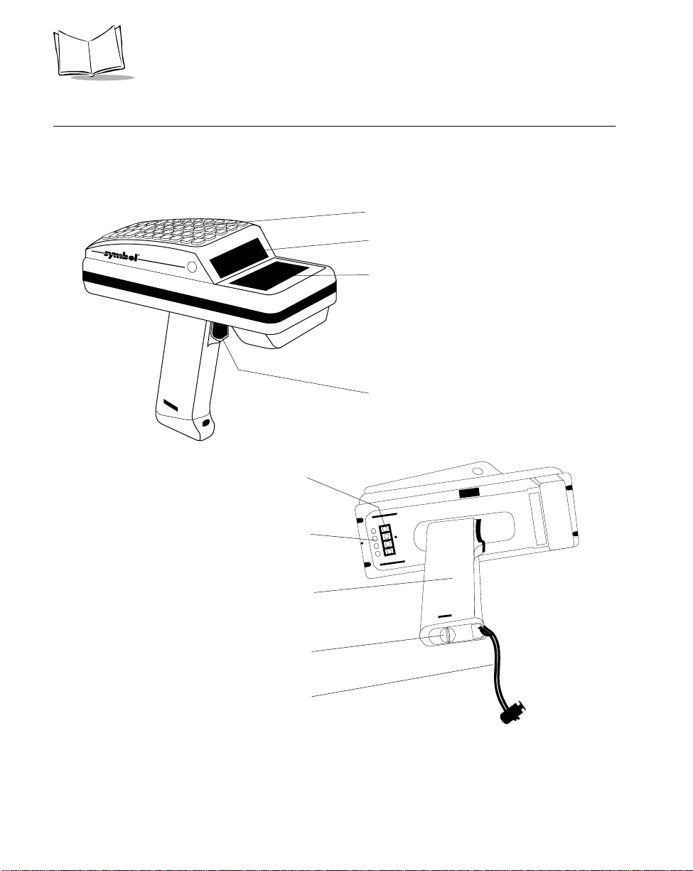
Terminal P arts and Basic Operation
The following paragraphs describe the parts and accessories of the Series 3800 terminals. For
information on the 3860, 3865, and 3866 cradles, refer to the individual guides listed in
Related Publications. For information about the PC Adapter, refer to Chapter 2.
Keyboard
Scan Window
LASER RADIO TERMINAL
LRT
Display
Trigger
1-2
Optical Connector
Battery
Recharge
Contacts
Battery Pack
Compartment
D Ring
Wrist Str ap
Figure 1-1. Series 3800 Terminal Parts
Page 19

The Series 3800 System
Display
The display shows eight 20-character lines — alphabetical characters, numerals, and
symbols. Back lighting is also available if your program allows it (refer to the section Back
Lighting on page 5-7).
Keyboard
The k ey board contai ns all the operating and data en try ke ys. Refer to the section The Series
3800 Keyboard on page 5-8 for more keyboard information.
D Ring
Twist the D-shaped ring on the end cap of the handle counter-clockwise to open the battery
pack compartment. Twist the D-ring clockwise to lock the compartment.
Battery Pack Compar tm en t
This compartment houses a NiCd battery pack or a carrier containing one 9-Vol t alkaline battery .
Batter y Rech arg e Contact s
These contacts a r e used to recharge the battery pack in the terminal while it is in a cradle or
connected to th e PC Ad ap ter. Refer to Chapter 6 for more information on battery charging.
Optical Connector
The optical connector in the terminal aligns with the optical connector in the cradle terminal
slot or the Printer Interface Module (PIM) to enable the terminal to send and receive data or
to print.
Trigger
Pull the tr igger to power on the terminal or to scan bar codes.
Wrist Strap
Place the wrist strap over your wrist to help you hold the terminal.
1-3
Page 20

Series 3800 Product Reference Guide
Accessories
The following accessories are available for 3800 terminals.
Batter y Charge r s
Series 3800 terminals use either a Nickel Cadmium (NiCd) battery or 9V battery pack. NiCd
batteries are charged using one of the charging accessories listed below.
Cradles
Cradles combi ne a communica tions device and b attery ch arger, and are available with either
one or four slots.
!
3860 Charging and Communications Module (CCM) — Four-slot module for
charging NiCd battery packs in the terminal and spare battery packs; also performs
communications between terminals and a host, modem, or printer. See Related
Publications.
!
3865 Cradle Base Unit — Single-slot cradle for charging NiCd battery packs; also
performs communications between terminals and a host, a modem, or a printer. See
Related Publications.
!
3866 Cradle Base Module —þFour-slot cradle for charging NiCd battery packs in
the terminal and for communicating between terminals and a host, a modem, or a
printer . See Related Publications.
Printer Interface Module (PIM)
The Printer Interface Module works with the PC Adapter to perform communications
between the terminal and a host PC without a cradle. Refer to the section The PC Ad apter
on page 2-11.
PC Adapter
The PC Adapte r w o rks with the PIM to com mun icate with the host PC with out a cradle or
to charge a NiCd ba ttery pac k in th e te r minal without a cradle. Refer to the se cti o n The PC
Adapter on page 2-11.
1-4
Page 21

The Series 3800 System
Radio a n d Ne tw or k Op ti ons
Spectrum One Network
The LRT 3800 includes an internal radio frequency transmitter/receiver for use in a Symbol
Spectrum One network.
The LRT 3824 includes a 2.4 GHz radio for use in Europe.
Spectr u m24 Ne twork
The LRT 3840 includes an internal radio frequency transmitter/receiver for use in a Symbol
Spectrum24 network.
Unpacking
Remove the clear protective tape from the display and the optical connector.
Save the shipping container for later storage or shipping. Inspect all equipment for damage
and make sure you have received everything listed on the packing slip.
If you find anything unsatisfactory or missing, contact your authorized customer support
representative im medi ate ly.
1-5
Page 22

Series 3800 Product Reference Guide
Before You Use the Terminal
The first time you use your Series 3800 terminal, or the first time you power it on after it has
been stored without the battery pack, follow these steps in orde r.
Install and Charge the Battery
1. Install a battery pack or alkaline battery and carrier in the terminal. Refer to Chapter
6, Maintaining the Series 3800, for instructions.
2. If you hear a repeated tone or see a message on the display, rech a rge or replac e the
battery pack. Ref er to Chapter 6, Maintaining the Series 3800, for m ore inf orma tion.
Load the Appropriate Software
What software you load and how you load it depends on the environment in which it will be used:
!
If this unit is intended for use in batch applications (3805) or in a Spectrum One
network environment (3800/3824), refer to Chapter 3, Batch and Spectrum One
Term i nal Setup, for information on downloading the software.
!
If this unit is intended for use in a Spectrum24 network environment (3840), refer to
Chapter 4, Spectrum24 RF Terminal Se tu p, for information on downloading the
software.
1-6
Page 23

Chapter 2
Hardware Setup
The CRD 3865 and CRD 3866 cradles and Charging and Communications Module (CCM)
3860 provide RS-232 communication, charging, and storage capability for the Series 3800
terminals.
The PC adapter provides charging and communication capability for a Series 3800 terminal.
This chapter provides instructions for setting up each of these devices for charging the 3800’s
NiCd battery, and for communicating with a host, printer, or modem.
2-1
Page 24
Series 3800 Product Reference Guide
3865 and 3866 Cradles
The CRD 3865 can be wall-mounted on a wall bracket for convenience.
Wall Mounting the 3865
To wall-mount the 3865:
1. Mark wher e y o u want th e cr a dle position ed on th e w a l l .
2. Using a fastener appropriate to the wall construction, insert and secure the fastener
(A in Figure 2-1). Let the head protrude slightly.
A
B
Figure 2-1. Wall Mounting the 3865
3. Slide the bracket down over the head of the fastener.
4. Remove the black tape covers from the cradle screw holds.
5. Slide the crad l e into the br ac ket.
6. Secure th e cr a d le to the b r a ck e t (B in Figure 2-1) using two #10 metal screws.
B
2-2
Page 25
Hardware Setup
Table Mounting the 3866
Note: Installing the suction cup feet is not mandatory but helps keep the
cradle in place.
1. On the bottom of the cradle, thread each of the four suction cup feet into the screw holes.
2. Wet the base of each suction cup and secure the cradle to a smooth tabletop by
pushing firmly down on the cradle (Figure 2-2).
Figure 2-2. Installing Suction Cups on
the CRD 3866
2-3
Page 26
Series 3800 Product Reference Guide
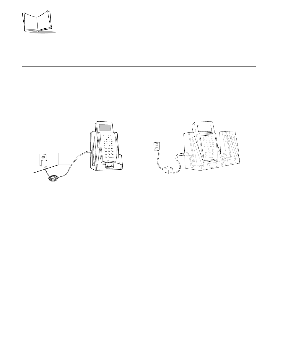
Connecting Power
Note:
The process for connecting power is the same for both cradles.
1. Connect the power supply cord’ s round plug to the power connector on the left side of the cradle.
2. Connect the power supply’s AC plug to a standard electrical outlet. The green and red indicators light for 3 seconds, blink for 3 seconds, then go out.
38663865
2-4
Figure 2-3. Connecting the CRD 3865 and CRD 3866
to a Power Source
Page 27

Hardware Setup
Connecting for Data Communication s
To connect the CRD 3865 or CRD 3866:
Note: Be sure to unplug the cradle’s power supply before connecting the
serial cables.
1. Turn off the PC.
2. Plug the RS-232 serial cable’s DB-25 connector in the cradle’s communication port
(Figure 2-4).
3. Connect the cable’s other connector to the host computer’s serial (COMM) port.
RS-232 Serial Cable
RS-232 Serial Cable
Power Supply
Charging
LED
COMM
LED
Power Supply
Charging
LED
CRD 3865 CRD 3866
Figure 2-4. Connecting the 3865 and 3866 Cradles
for Communications with Computer, Printer, or Modem
COMM
LED
2-5
Page 28
Series 3800 Product Reference Guide
3860 CCM
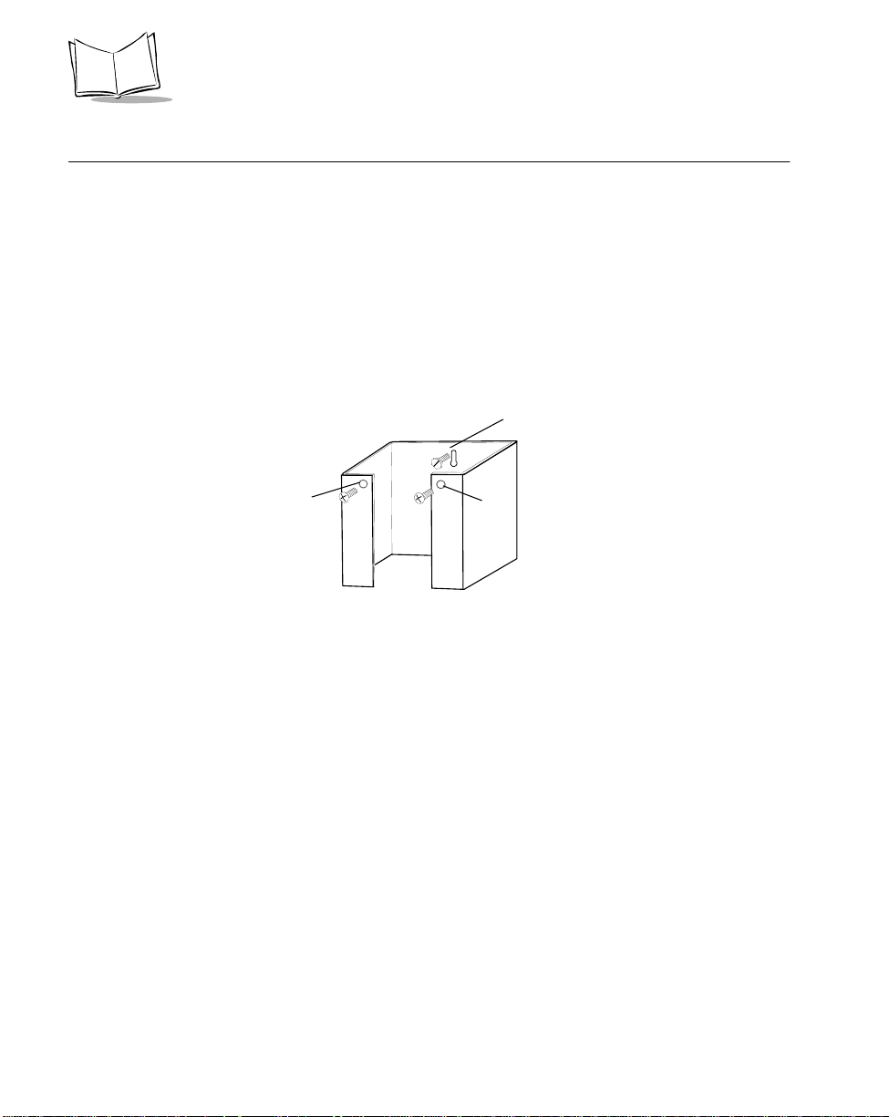
Wall Mounting the CCM
The 3860 CCM can be table or wall mounted.
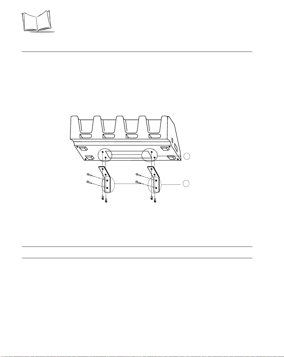
To wall mount the CCM:
1. Attach the wall-mounting brackets to the bottom of the CCM using the four crosshead machine screws provided, as shown in Figure 2-5:
Attach Bracket
1
to CCM
with 2 Screws
Attach Bracket
2
to Wall
with Appropriate
Hardware
Figure 2-5. Wall Mounting the 3860 CCM
2. Position the CCM with attached brackets on the wall.
3. Insert the appropriate wall-mounting hardware into the bracket holes as shown in
Figure 2-5 and secure.
Note:
Appropriate wall-mounting hardware to be provided by customer.
2-6
Page 29
Hardware Setup
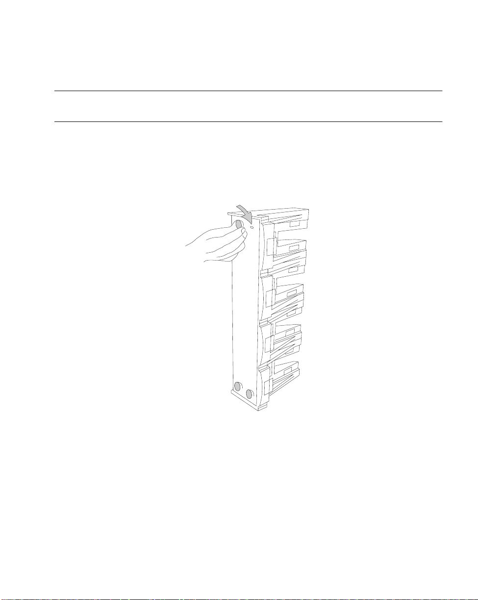
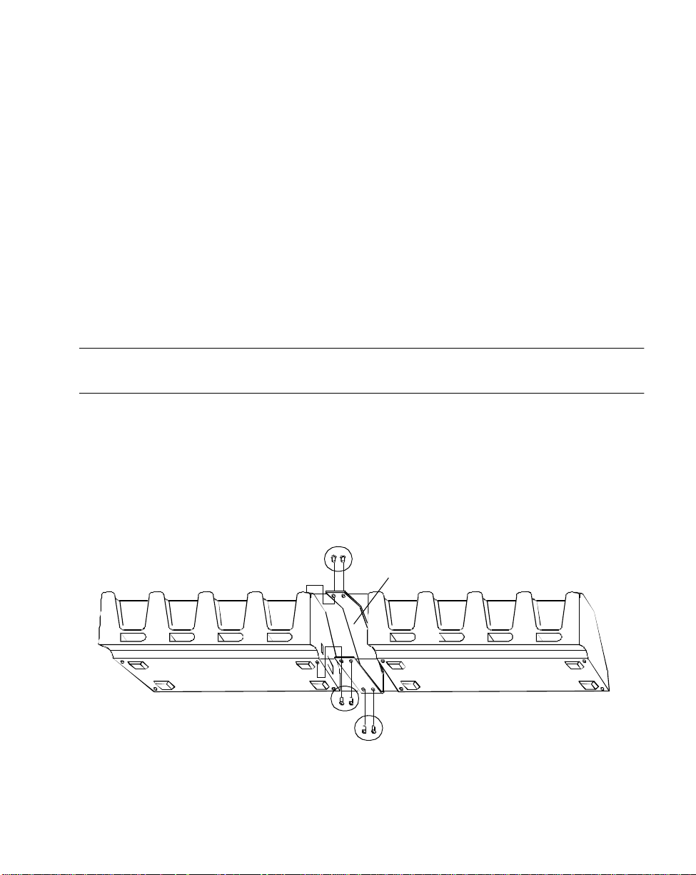
Coupling CCMs
Up to f our 3860 C CMs ca n be coupled together fo r table o r wall mounting, w ith po w e r
provid ed by a single power supply attached to the left-most CCM.
To couple two or more CCMs for table or wall mounting:
1. Verify that add-on 3861-101 kit contains the following parts:
1 coupling bracket
"
6 cross-head screws
"
2 flat-head screws
"
2. On the add-on (or right-hand) CCM, use 3/16-inch driver to remove the jack screws
securing the comm unications por t, ONE A T A TIM E, and replace them with the flathead screws.
Note: Be sure to remove the jack screws one at a time; otherwise , the
connector will fall into the housing.
3. Place the coupler between the CCMs, aligning the holes in the coupler to the holes
in the CCM’s base (Figure 2-6).
4. Install 6 cross-head screws through the coupler into the CCMs and tighten.
5. If you wish to wall mount the coupled CCMs, proceed as directed in Wall Mounting
the CCM.
Screws
Coupling
Screws
Figure 2-6. Coupling two 3860 CCMs
2-7
Page 30
Series 3800 Product Reference Guide
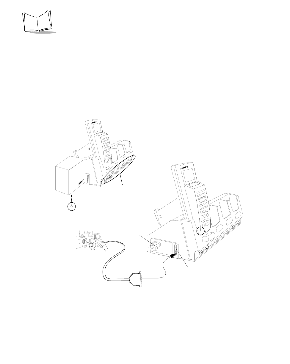
Connecting Power to the 3860 CCM
Only the power connection is required for charging batteries in the CCM.
1. Install the powe r s upply. a. Attach the power supply to the left side of the CCM as shown in Figure 2-7 using
two cross-head screws.
b. Connect the power supply plug to an AC wall outlet.
2. When the CCM is connected to power, all the LEDs flash at the same time for 3
seconds, flash once from left to right, and turn on for 3 seconds before going out.
Insert Screw
Power Supply
LEDs
3860 CCM
2-8
Insert Screw
Host
Powe r Port
RS-232
Serial Cable
Communication
Figure 2-7. Connecting the 3860 CCM for
Charging and Communications
Port
Page 31

Hardware Setup
Connecting the 3860 for Serial Communications
Note: Both the communications cables and the power supply connection are
required for performing communications through the CCM.
1. Turn off the PC.
2. Plug the RS-232 serial cable’s DB-25 connector in the cradle’s communication port.
3. Connect the cable’s other connector to the host computer’s serial (COMM) port.
Daisy-Chaining Two or More 3860 CCMs
Up to twenty-four 3860 CCMs can be daisy-chained together for charging and
communications. To daisy chain two or more groups of four CCMs requires:
!
one 25-pin, male-to-female, straight-through RS-232 cable per group of coupled
CCMs
and
!
one power supply per group of coupled CCMs.
Depending on how close together you place the CCMs, the cables can be from 1-foot to 10feet long.
One Power Supply
and RS-232 Cable
per Group of
Coupled CCMs
(a “Group” Can
Number from
1 to 4 CCMs)
Figure 2-8. Daisy-Chaining Multiple 3860 CCMs
First
Coupled
Group
RS-232
Cable
Second
Coupled
Group
2-9
Page 32

Series 3800 Product Reference Guide
To chain the CCMs:
1. Couple the CCMs as directed in the section Coupling CCMs.
2. In the first coupl ed secti o n , con ne ct the ser ial cable to the left-most CC M.
3. Connect the RS-232 cable’s (male or female) DB-25 connector in the serial port of
the right-most CCM in the first coupling.
4. Connect the (male or female) DB-25 in the serial port of the left-most CCM in the
second coupling.
5. Connect the power supplies for each coupled section as directed in Connecting
Power to the 3860 CCM.
2-10
Page 33

Hardware Setup
The PC Adapter
The PC Adapter works with the Printer Interface Module (PIM). With this arrangement, you
can perform these tasks:
!
Communicate to and from the PC without a 3860, 3865, or 3866 cradle
!
Charge the NiCd batte ry pac k in the terminal without a cradle.
Parts of the PC Adapter
The parts of the PC adapter are indicated by the circled numbers in Figure 2-9 and described
in the followi ng steps.
3
2
1
4
Figure 2-9. Parts of t he P C Adapter
1. Battery c harge indicato r LED flash es when the terminal po wer is tur ned on. It flashes
while the te rminal's NiCd battery pack is be ing char g ed. Alkaline batteries a re not
recharged.
Note: When power to the PC Ad apter is turned on, NiCd battery charging
begins automatically and continues for 14 hours.
The L ED flash es onc e wh en the terminal is turn ed on. It remains s te a d y wh il e the
ter m inal is pow ered and blinks slo w l y during downloading.
2. The RS-23 2 2 5 -p in port is used to att ach a null mo dem cable that conn ects to a PC
or other RS-232 device. See Appendix A for null modem pin-outs.
2-11
Page 34

Series 3800 Product Reference Guide
3. The DE-9onnector is used to attach the PIM’s D E-9 connector.
4. The power supply po r t is used to att ach the 16-Volt power supply.
Connect the PC Adapter to 3800 and Serial D evice
To set up the PC Adapter (refer to Figure 2 -10 ):
PIM
Optical
Connector
Connector
DB-25RS-232 Cable
PC
Adapter
Power
Supply
Port
Power S upply
DB-9 Port
Figure 2-10. Setting Up the PC Adapter
1. Turn the PC and terminal OFF.
2. P lug the DB - 9 end of the PIM into the DB-9 port of the PC Adapter.
3. Attach the PIM’s optical connector to the LRT/LDT’s port.
4. Connect the RS-232 cable’s DB-25 connector to the PC Adapter.
5. Plug the other end of the RS-232 cable into the RS-232 device.
6. Plug the jack end of the 16-Volt power supply into the power supply port.
7. Plug the 16-Volt power supply’s cube into an electrical outlet. The battery charge indicator LED flashes when the terminal power is turned on.
2-12
Page 35

Chapter 3
Batch and Spectrum One Termina l Setup
Introduction
Before using a Series 3800 terminal, perform the following procedures:
!
Install the battery (refer to Ch ap ter 6, Maintaining the Series 3800)
!
Charge the battery, if using a Nickel Cadmium (NiCd) rechargeable battery (refer to
Chapter 6, Maintaining the Series 3800)
!
Load the system files and application(s).
Programs are stored in the terminal’s nonvolatile memory (NVM), also called the application EEPROM.
Hardware Requirements
The following equipment is required to initialize a batch or a Spectrum One radio terminal:
!
3800 or 3805 ter mi n a l
!
One or more 3860 or 3865 cradles, or 3866 CCM
OR
!
PC adapter with Printer Inte r f ace Module (PI M )
!
A straight-through RS-232 null modem cable with male DB-25 connector at one end
and female DB-25 connector at the other end
!
Power Supply
!
Host Computer
3-1
Page 36

Series 3800 Product Reference Guide
Refer to Chapter 2, Hardware Setup, for instructions on setting up the cradles or PC Adapter
for communications.
Communications
For terminals being us ed in a direct communicat ions (batch) environme nt or a Spectrum One
network environment, applications are transferred from a host computer to the terminal:
!
over a communications line using a null modem connected to the cradle
OR
!
throughthe PC Adapter.
The procedure uses the SENDHEX command on the host computer and the Program Loader
function (from Command Mode) on the terminal.
Note: For details on the SENDHEX command, refer to the Series 3000
Application Programmer's Manual.
Other software may be used in place of SENDHEX.
3-2
Page 37

Batch and Spectrum One Terminal Setup
Loading the Progra m
To download the program, initiate the communications software on the host computer and
terminal as described in the following sections.
Note: Communications parameters specified on the host and the terminal
must match. These p arameters typically are:
38400 bps
7-bit parity
Odd parity
Xon/Xoff flow control
To program the EEPROM, the terminal must be connected to the
host through a cradle, 3860 CCM, or PC Adapter with PIM.
Initiate Host Commun icat ions Software
Note: To c a n cel comm unicati ons at any time during the session, press
CLEAR on the terminal. The session stops immediately.
1. Power on the host computer .
2. Start the communications program.
3. Enter the SENDHEX command.
sendhex pgmname 38400 com2
where:
SENDHEX is the command
pgmname is the application being loaded (.hex extension is optional)
parameters Communications parameters follow the program name.
Parameters include baud rate, communications port, data
bits, parity, and flow control. To accept the default
parameters, do not ent er a value.
In the example, the baud rate is set to 38400 bps and the communications port to
COM2. The default values are accepted for the remaining parameters.
3-3
Page 38

Series 3800 Product Reference Guide
Note: Versions of SENDHEX earlier than 3.0 do not support flow control.
If you use an earlier version and encounter communication errors, use
a lower baud rate.
4. SENDHEX display s the prom pt :
Press <Enter> to begin communications.
5. Do NOT press <ENTER> yet. Before starting communications (refer to Starting
Communications), set up the terminal as dire cted in Initiate Terminal
Communications.
Initiate Terminal Communic ations
1. Boot the terminal to c ommand mode . Refer to Ch apter 5, Operating the Series 3800,
for a list of the boot to command mode sequences.
The termina l displays the fol lowi n g:
COMMAN D M ODE
Select func tion
Self test
2. Scroll through Command Mode options using UpArrow or DownArrow until
"Program loade r" is displayed. Press <ENTER>.
3. The t e r m in al displ ay s :
Progra m l oader
WARNIN G: EEPROM
WILL BE ERASED
CONTINUE? <ENT>
Before loading the new application, erase the NVM’s original contents.
Note:
T o cancel this operation, press <CLEAR>.
4. Press <ENTER> to erase the EEPROM. Wait while the EEPROM is erased. When complete, t he program prompts for the
communications parameters.
3-4
Page 39

Batch and Spectrum One Terminal Setup
5. Baud Rate.The te rm inal disp la ys:
Comm Parameters
Baud
4 960 0
Scroll through the list using UpArrow or DownArrow. When the correct rate is
displayed (38400 is recommended), press <ENTER>.
6. Data Bits. The terminal di spl ays:
Comm Parameters
Data Bits
7
Press <7> (recommended) or <8> to specify data bits, or scroll through the list using
UpArrow and DownArrow. Press <ENTER> when the corr ect value is di splaye d.
Note: If 8 data bits is selected, the pr o gr a m selects "No parity" and s k ips
the next step.
7. Parity. If 7 data bits is select ed, the terminal displays:
Comm Parameters
Parity
Odd
Press the firs t l etter of a parity option (Even, Odd, None, Space, or Mark), or scroll
using UpArrow and DownArrow and press <ENTER> when the correct value is
displayed.
8. Flow Control. The terminal displays:
Comm Parameters
Flow Control
None
Press the first letter of a flow control option (None, Xon/Xoff, or RTS/CTS), or scroll
using UpArrow or DownArrow and press <ENTER> when the correct value is
displayed.
3-5
Page 40

Series 3800 Product Reference Guide
Starting Communications
1. The terminal is ready to receive the program from the host PC and displays:
Comm Parameters
Start? <ENT >
2. Press <ENTER> on the terminal.
3. Press <ENTER> on the host computer. SENDHEX begins transmitting the program
image. When communications are established, the terminal displays:
Progra m l oader
Receiv ing : XX XX
During program loading, the display shows the program segment address being
transferred (XXXX).
4. When the transmission is complete, the terminal displays:
Progra m l oader
Status 0000
A status of 0000 (all zeros) indicates a successful transter. Other status values
indicate an error. These values are provided in Appendix B, Communications Status
Codes.
If you received an error, press <Clear> on the terminal to return to the Command
Mode main menu.
Ending Communications
To return to the Command Mode main menu:
1. Press <Clear> on the terminal.
2. Power down the terminal.
3. Detach any cables connected to the terminal.
4. Reboot the terminal using the appropriate cold boot sequence desc ribed in Chapte r
5, Operating the Series 3800, in the section Booting a Series 3800 Ter minal .
3-6
Page 41

Chapter 4
Spectrum24 RF Terminal Setup
Spectrum24 Terminals
In Spectrum24 terminals, wireless connectivity is accomplished using standard
communications protocols. Because they are standard, the protocols are generalized and take
up considerably more space on the terminal’s NVM than was required for Spectrum One
terminals. Because there is less space available in NVM for application files, the terminal
operates with an additional megabyte of non-volatile memory or flash disk. This extra
memory is used to reduce not only the boot times but also the time and resources required to
load applications into the terminal. The flash disk also offers the possibility of running
multiple applicati ons f rom the same te r minal (r efer to the section Multiple Applications on
the Same Term inal for more information. With version 3.03 or later of the system software
(LWP . HEX ), th e termin al can also run dia gn osti c tools.
Accessing the Flash Disk
The flash disk is accessed through a drive r, FLASHDSK.SYS, which makes the flash disk
appear to a program as another disk drive (E:). The drive has characteristics of fast re ading
but slow writing (e.g., even for the smallest files, the write process takes 3-4 seconds). These
characteristics make it ideal for files that are written once, accessed often, and seldom
updated.
®
We recommend that you use the flash disk (E:) mainly for application and configuration file
storage. T o avoid overwriting the flash disk by mistake, the flash disk is set to read-only mode
for normal operation. The software installation or application software takes care of write/
read mode switching for you.
4-1
Page 42

Series 3800 Product Reference Guide
Standard Spectrum24 Software
The Series 384X comes with the system software installed, including:
!
Spectrum24 radio drivers
!
TCP/IP software
!
configuration files
!
various utilities.
A BIOS of version 1.09 or later is required.
The default files c ov er mo st expecte d ins tallatio n s/i nitial izat ions with minor changes as
detailed in this chapter.
If your requirements are more advanced, refer to the Spectrum24 Network Development Kit
documentation for more information on the Spectrum24 RF network, SLAODI.COM, the
Symbol-provided ODI driver, and the configuration file setups required for various
platforms.
Boot Options & Internet Addressing
Each Series 384X requires a unique internet address (IP address), allowing messages it sends
and receives to be correctly routed over networks conforming to the TCP/IP protocol
standards. These addresses can be administered and entered manually, or administered and
allocated by a server on the network.
By default, the Series 3800 uses NOBOOT (manual entry) to define the IP address. To set the
IP address, use the CFG24 utility described later in this chapter in the section Initializi ng th e
Series 384X.
Two protocols are d efined for the IP address allocation on the network: BOO TP and DHCP.
T o allocate IP addresses through a BOOTP or DHCP server , you must change the boot option
in the configurator using the Boot Mode parameter .
4-2
Page 43

Spectrum24 Terminal Setup
Initializing the Series 384X
To initialize a Series 384X which has L WP.HEX version 3.03 or greater loaded:
Note: This section covers specific settings required on first booting the Series
384X out of the box. For a complete review of the CFG24 screens,
refer to Appendix E, Spectrum24 Utilities.
1. Insert a charged battery in the Series 384X. Refer to Chapter 6 for instructions on
charging and installing a battery.
2. Cold boot the Series 384X.
For the 35-key 384X:
Press and hold <# + SPACE + FUNC>.
"
Press and release PWR.
"
Release <# + SPACE + FUNC>.
"
For the 46-key 384X:
Press and hold <A + B + D>.
"
Press and release PWR.
"
Release <A + B + D>.
"
3. The Series 384X loads software, then brings up the Spectrum24 Configurator
(CFG24) menu, shown in Figure 4-1.
Note: CFG24 comes up automatically after the first initial ization out o f the
box. On subsequent initializations, type CFG24 at the DOS prompt
to bring up the configurator.
4-3
Page 44

Series 3800 Product Reference Guide
CONFIGURATOR 1.XX
View config params
Net Id
Subnet Mask
Default Router
Termina l IP Ad dress
Diversi ty
Terminal Sleep Mode
Boot Mode
Power Management
Exit
#$, Clear, Ent er
Figure 4-1. CFG24 Main Menu
On the Series 384X screen, the top and bottom lines of the menu are displayed, and
the remaining lines are viewed by scrolling. In this menu, pressing <CLEAR> has the
same effect as selecting Exit.
4. The Series 384X initially is set to NOBOOT mode. To configure the terminal for
operation, set up the parameters provided in Ta ble 4-1 (the procedures are detailed
in the steps b elow) .
Table 4-1. Spectrum24 Configuration Parameters
Net Id The Net Id identifies the radio network and differentiates
between different radio networks. All equipment on o ne
network must use the same Net Id.
Set to the same value spe cified for the S pec trum2 4 Ac cess P oin ts
(APs).
Boot Mode The boot mode indicates the source of the terminal’ s IP address.
If this value is set to “Manual en try”, you must enter a terminal
IP address thro ugh CFG24.
4-4
Page 45

Spectrum24 Terminal Setup
Table 4-1. Spectrum24 Configuration Parameters (Continued)
Terminal IP Address Required if you are not using a boot server to allocate IP
addresses (BOOTP or DHCP).
Set as advised by your LAN administrator.
Note: Take care entering this value! The IP address must be
unique in the network or communications will be
unpredictable.
Subnet Mask Set as advised by your LAN administrator.
Note: If you change boot mode, the value set by a server
overrides this value.
Default Router The default router is the address of the node where all packets
destined for remote networks will be sent.
Set as advised by your LAN administrator.
Note: If you change boot mode, the value set by a server
overrides this value.
Diversity Determines whether the radio firmware attempts to use one or
two antenna ports for communicat ions. It is important to match
this setting with th e actual number of ant en n as in use.
If set to “Yes”, the radio firmware attempts to use both antenna
ports for communications.
The Series 384X has two antennas. Set to “Yes”.
Terminal Sleep Mode Determines whether radio is powered off after the terminal
enters sleep mode due to inactivity. Refer to Appendix E for
more information.
The default value is “On”.
Power Management If power management is set to PSP, the radio powers up only
when there is traffic on the network. I f it is set to CAM, the
radio is always ready to receive. Use the PSP setting to save
battery li fe.
The default value is “PSP”.
a. To view the Series 384X’s default parameters, select VIEW CONFIG PARAMS
(Figure 4-2).
4-5
Page 46

Series 3800 Product Reference Guide
This screen is for display only; it is not a data entry screen. Us e i t to review the
terminal’s IEEE (or MAC) address, IP address, and Net Id. Press <CLEAR> or
<ENTER> to return to the main menu.
VIEW CO NFIG PARAMS
Termina l IEEE addr
00:a0:f 8:0 0:02: b8
Termina l IP Ad dress
157.235 .93 .186
Ne t Id = 150
#$, Clear, Enter
Figure 4-2. View Configuration
Parameters Screen
b. To change the N et Id, select Net Id from the CFG24 Menu. The Net Id screen
(Figure 4-3) is displayed.
NET ID
Enter Net Id(he x):
150
4-6
BkSp, Clear, Enter
Figure 4-3. Net Id Screen
To change the current Net Id value, backspace over the current value and type a
new value, in hexadecimal format, in the range 101 to 1FE. Alphabetical hex
values ca n appear in uppe r or lower case. The defau l t value is 101.
Press <ENTER> to effect the change. P r ess <CLEAR> to exit without changes.
Page 47

Spectrum24 Terminal Setup
c. Select Subnet Mask from the main configuration menu. The Subnet Mask scre en
(Figure 4-4) is displayed.
SUBNET MASK
Enter Subnet Ma sk:
255.25 5. 255.0
Bksp, Clear, Enter
Figure 4-4. Subnet Mas k Scree n
T o change the current Subnet Mask setting, backspace over the current value and
type a new value, in decimal form. Each part of the four-part address must be in
the range 0 to 255. The default value is 255.0.0.0.
Press <ENTER> to effect the change. P r ess <CLEAR> to exit without changes.
d. Select Default Router from the main configuration menu. The Default Router
screen (Figure 4-5) is displayed.
DEFAUL T ROUTER
Enter Default Router
157.23 5. 93.17 8
BkSp, Clear, Enter
Figure 4-5. Default Router Screen
To change the current Default Router setting, backspace over the current value
and type a new value, in decimal form. Each part of the four-part address must
be in th e ra nge 0 to 255. The defa ult va l ue i s 0.0.0.0.
Press <ENTER> to effect the change. P r ess <CLEAR> to exit without changes.
4-7
Page 48

Series 3800 Product Reference Guide
e. Select Terminal IP Address from the main configuration menu. The Terminal IP
Address screen (Figure 4-6) is displayed.
TERMINAL IP ADDRESS
Enter IP address:
157.235. 93 .186
BkSp, Cl ear, Ent e r
Figure 4-6. Terminal IP Address Screen
T o change the current T erminal IP Address, backspace over the current value and
type a new value in decimal form. Each part of the four-part address must be in
the range 0 to 255. The default value is 0.0.0.0.
Press <ENTER> to effect the change. P r ess <CLEAR> to exit without changes.
f. Select Diversity from the main configuration menu. The Diversity screen (Figure
4-7) is displayed.
DIVERSI TY
2 anten nas (Yes/No)
Yes
4-8
#$, Clear , E nt er
Figure 4-7. Diversity Screen
T o change the current Diversity setting, use the cursor keys to toggle between
#$
the settings “Yes” and “No”. For the Series 384X, set Diversity to “Yes”.
Press <ENTER> to effect the change. P r ess <CLEAR> to exit without changes.
Page 49

Spectrum24 Terminal Setup
g. Select Terminal Sleep Mode from the main configuration menu. The Terminal
Sleep Mode screen (Figure 4-8) is displayed.
TERMINAL SLEEP MODE
Radio state:
On
#$, Cl ea r, Enter
Figure 4-8. Terminal Sleep Mode Screen
To change the current Terminal Sleep Mode, use the cursor keys to toggle
#$
between the “On” and “Off” settings. The default setting is “On”.
Press <ENTER> to effect the change. P r ess <CLEAR> to exit without changes.
h. Select Boot Mode from the main configuration menu. The Boot Mode screen
(Figure 4-9) is displayed.
BOOT MODE
IP address from:
Manual entry
#$, Clear, Enter
Figure 4-9. Boot Mode Screen
To change the current boot mode, use the keys to toggle among the three
#$
settings: “Manual entry”, “BOOTP”, and “DHCP”. Refer to Appendix E for a
complete explanation of the three boot modes.
Press <ENTER> to effect the change. P r ess <CLEAR> to exit without changes.
4-9
Page 50

Series 3800 Product Reference Guide
i. Select Power Management from the main configuration menu. The Power
Management screen (Figure 4-10) is displayed.
POWER MA NAGEM ENT
Radio Po wer Mod e
PSP
#$, Clear, Enter
Figure 4-10. Power Management Screen
#$
To change the current power management mode, use the
keys to toggle
betwe en the set t ings “PSP” and “CAM”. The default setting is “PSP”.
Press <ENTER> to effect the change. P r ess <CLEAR> to exit without changes.
5. When all of your changes are made, press <CLEAR> to return to the main configuration menu.
6. Select Exit from the main configuration menu and press <ENTER> to exit the configurator.
The Series 384X di s plays t he message:
...upd ating config
data
and proceeds with the initialization which writes the configuration values to a
R/W non-volatile section of radio flash memory.
4-10
Page 51

Spectrum24 Terminal Setup
Initiating Network Connecti on
As the in iti ali zati on continues, the termin al attempts to associate w ith th e Sp ec tr um 2 4 AP
using the default or newly entered Net Id.
Series 384X Association with AP Not Successfu l
If the Series 384X is unable to associ ate w ith t he AP (the Net Id is wrong or forgo tten), it
displays the message:
STAT24 Ver 1.XX
NOT Associated
for a few seconds. A second message foll ows:
Termin al cannot as socia te with AP . Y ou’re
out of range or not configured. C trl+C to end
or oth er key to re try. Strike any key when
ready. ... .
The Series 384X continues trying to connect until the attempt is cancelled.
1. Press <Ctrl + C> to end the attempt. The Series 384X displays the message:
Halt Batch proce ss Y/
N?
2. Type Y to exit to the DOS prompt (D:).
3. At the DOS prompt, type CFG24 and press <ENTER> to initiate the Configurator
and bring up the Configurator screen.
4. V erify the Net Id with the LAN administrator to ensure you are entering the correct
value.
5. V e rify other parameters and proceed as directed in the section Initializing the Series
384X, beginning with step 4a.
Series 384X Association with AP Suc cessful
If the association is successful, the terminal begins operating using the software files loaded
on the flash disk.
On first initialization, you probably don’t have applications loaded. Proceed with loading the
applications as directed in Installing Application Software on Flash Disk. On subsequent
init i aliz a t ions, if onl y one ap plic a t i on is loaded, t hat ap plication i s dis played automatically.
4-11
Page 52

Series 3800 Product Reference Guide
If you loaded multiple applications, a application selection menu is displayed early in the
initialization process. Select the application to load for the current session and proceed.
4-12
Page 53

Spectrum24 Terminal Setup
Installing Application Software on Flash Disk
Note: LWP.HEX version 3.03 or greater is required on the Series 384X for
this process. If you are not sure of the terminal’s hex version, boot
(initialize) the Series 384X . T he h ex version is dis play ed for
approximately 5 seconds during the initialization process.
Installing application software on the Series 384X flash disk includes downloading a HEX
file to the Series 384X, using SENDHEX on the PC and a batch file (_L.BAT) that runs
Program Loader on the terminal, then re-initializing the terminal. On the initial boot after a
software downl oad , the WWC copie s t he s oftware files on to the flash disk, and rememb ers
that the copy occurred, ensuring that it is not repeated each time the WWC is booted.
The hardware required for performing the download includes:
!
Series 384X terminal
!
configuration cradle (3860, 3865, or 3866)
!
DOS PC
!
RS-232 serial null modem cable
Initiate Host Communicat ions on the PC
To update the hex image:
1. Power on the host computer .
2. On the PC, change to the directory where the application’s hex file is stored and type
the following command at a DOS prompt:
SENDHEX <file name> 384 [1|2]<ENTER>
4-13
Page 54

Series 3800 Product Reference Guide
where:
SENDHEX is the command
<file name> is the hex file for the application being loaded. There may be other
application hex files which load other software (e.g., STEP version 2.6.0 or
greater, or TelNet Clients 3.0 or greater) to the flash disk.
Note: Be sure to use applications that are flash-disk enabled.
38400 is the baud rate.
[1|2] sets the host communications port the cradle is attached to.
The following m essage i s disp layed :
Press <ENTER> when remote is ready. ESC to abort...
3. Do NOT press <ENTER> yet. Set up the Series 384X using the _L.BAT utility as
directed in the section Running _L.BAT.
Running _L.B AT
1. Place the Series 384X in a configuration cradle.
2. Power the terminal on.
3. At a DOS prompt on the 384X, type _L<ENTER> using the keystrokes listed below . For the 35-key 384X:
<SHF><FUNC><K><L><ENTER>
For the 46-key 384X:
<SHF><FUNC><G><L><ENTER>
4. The terminal boots and displays the message:
Symbol Tech nologie s
NVM Loader 2.X-XX
Connec tin g to Ho st
5. Press <ENTER> on the host PC.
6. The batch file runs Program Loader with the communications parameters set to
38,400 bps, 7 data bits, odd pari ty, and no flow control. The 384X displays the
screen:
4-14
Page 55

Spectrum24 Terminal Setup
Symbol Tech nologie s
NVM Loader 2.09- XX
Addres s: XXX X
7. When the hex download is complete, the 384X automatically reinitializes (warm
boots) and copies the files in the software package to the flash disk. If the 384X does
not reinitialize, re-initialize the 384X using the following key sequence:
Note:
The 384X must be re-initialized to copy the software to the flash disk.
For the 35-key 384X:
Press and hold the + and / keys.
"
Press and release PWR.
"
Release the + and / keys.
"
For the 46-key 384X:
Press and hold the 4 and 5 keys.
"
Press and release PWR.
"
Release the 4 and 5 keys.
"
Note: If you get a timeout message at any time during the procedure, press
<ENTER> to return to the s creen.
8. The soft ware is copied on to the fla sh disk.
9. Proceed with initializing the network connection as described in the section Initiating
Network Connection.
Note: If you downloaded multiple applications, a “select” screen appears
before the 384X attempts to associate with an AP , requesting that you
select an application.
4-15
Page 56

Series 3800 Product Reference Guide
Updating System Software on Flash Disk
Updating the LWP hex image means loading the new system files on the flash disk using the
SENDHEX utility on a PC. It is po ssible to pe rf orm thi s update on m ultiple terminals in a
cradle at one time, with each terminal running Program Loader from Command Mode.
Note: The Series 384X is shipped with the LWP hex file installed. Use this
procedure ONLY:
• to load a new version of L WP greater than 3.03
• if you experience serious difficulties
• if you are so direct ed by Sy mbol’ s Technica l Su ppo rt sta f f .
Option: Using _L.BAT to Update System Software
If the Series 384X terminal contains a LWP hex file of version 3.03, you can follow the
instructions for installing application software on the flash disk using _L. BAT through step
6, when the terminal is reinitialized. Proceed to step 6 of this procedure at that point.
Note: Be sure, when entering the SENDHEX command on the PC, to issue
the command from the di rect ory where the he x fi le (LWP.HEX ) is
stored.
Initiate Host Communicat ions on the PC
To update the syste m sof twa r e :
1. Power on the host computer .
2. On the PC, change to the directory where the system hex file (LWP.HEX) is stored
and type the following command at a DOS prompt:
SENDHEX LWP 384 [1|2] <ENTER>
4-16
Page 57

Spectrum24 Terminal Setup
where:
SENDHEX is the command .
LWP is the hex file being loaded. LWP.HEX is the hex file specifically for
the syste m file s. There may be other hex file s which load other
software, such as applications, to the flash disk.
384 is the baud rate (38,400 bps).
[1|2] sets the host’s com m un icat ion port the cra dle is connected to.
The follow ing mess age i s displayed :
Press <ENTER> when remote is ready. ESC to abort...
3. Do NOT press <ENTER> yet. Set up the terminal as described in Initia te Terminal Communications.
Initiate Terminal Commun icati ons
1. Power off t he Series 384X and place it in the c r adle.
2. Boot the 384X to Command Mode. For the 35-key 384X:
Press and hold <BKSP + Shift>.
"
Press and release PWR.
"
Release <BKSP + Shift>.
"
For the 46-key 384X:
Press and hold <A + B + D>.
"
Press and release PWR.
"
Release <A + B + D>.
"
The terminal displays the function selector screen:
COMMAN D M ODE
Select func tion
Self Test
4-17
Page 58

Series 3800 Product Reference Guide
$
3. Scroll through the Command Mode options using or until “Program loader”
#
is displayed. Press <ENTER>.
4. The 384X displays:
Progra m l oader
WARNIN G: EEPROM WILL
BE ERASED
CONTIN UE?
<ENT>
Note:
T o cancel this operation, press <CLEAR>.
5. Press <ENTER> to erase the EEPROM. Wait while the EEPROM is erased. When complete, t he program prompts for the
communications parameters.
6. Set the parameters to 38,400 bps, 7 data bits, odd parity, and no flow control. Press <ENTER>.
Start Communications
1. The 384X displays:
Comm Parameters
Start? <ENT >
2. Press <ENTER> on the 384X.
3. The 384X displays:
Comm Parameters
Receiv ing : XX XX
If the host is not ready or if the cable is not connected properly between the host PC
and the cradle, the 384X displays:
Awaiti ng D S R
4-18
Page 59

Spectrum24 Terminal Setup
4. Press <ENTER> on the host PC to start the download. The 384X displays:
Progra m l oader
Status XXXX
5. When the transmission is complete, the 384X displays:
Progra m l oader
Status 0000
A status of 0000 (all zeroes) indicates a successful transfer . If the status is other than
0000, check the cable connections between the host PC and the cradle and repeat the
process. If the problem persists, contact the Symbol Support Center for assistance.
6. When the download is complete, the Series 384X displays the following query:
LWP.HE X V er X. XX
Loadin g s ystem files
1. Ref orm at fl as h
2. Use flash as-is
Select [1,2 ]:
Caution
Reformatting the flash removes all system files and applications stored on
the fl a s h dis k.
Select 1, Reformat flash, ONL Y if you have problems with the Series 384X’s
operation. Se le ct 2, Use flash as-is, to update the fl as h w hile r e taini ng the
existing contents.
7. If you select 1, the 384X displays the messag e:
Are You sure Y o r N
8. Press Y to continue with the reformat or N to cancel and press <ENTER>.
The Series 384X fini shes reformattin g (if requested), cop ies the files to the flash disk ,
and executes them.
4-19
Page 60

Series 3800 Product Reference Guide
Compatibility Issues When Updating
While the order in which software packages are loaded is not important, we recommend
loading the system files, LWP .HE X, first, before loading any application files. You don’t have
to reload existing applications that conformed to previous standards for flash disk
applications. Loading just the s ys tem files allows the o ld applications to run wi th updated
system software.
Note:
Some configuration changes may be required.
Compli c at ions: N am i n g Applicat ions
In versions of LWP.HEX for flash disk terminals prior to version 3.03, parameters were
defined in N ET.CFG to specify the applicat ions t hat would run on the t erminal. If only one
application was used and no appl ications were defined in NET.CFG, the system gave the
application the default name, APP. This can cause problems if you plan to add more
applications to terminals using version 3.03 HEX files.
With LWP.HEX 3.03, the application entries in NET.CFG are not longer required. The
system now decides which applications are installed on the terminal by scanning the flash
disk’s directories and files. If you had an original application with the default name APP, it
will show up in the application selection menu as APP. If you updated that old application
(e.g., created a version 3.03 HEX file of the application), the application selection menu will
contain both versions, one called APP and one by the “real” name (e.g., STEP).
Because of this potenti al problem, if ALL the software on the flash disk is being replaced in
the update, we re commend reformatting the fl ash disk using FLSHFMT. Reformatting delete s
ALL th e f iles on the flash di sk and eliminates this duplication.
Note: DO NOT run the FLSHFMT utility unless all the HEX files,
including LWP.HEX, ar e avai labl e to rec reat e the fl ash disk file
system.
Complications: Syst em Parameters
In flash disk ter min als with a LWP . HEX ve rsion pr ior to 3.03 , some system parameters were
changeable only by editing NET.CFG (e.g., power management mode, boot mode, and
diversity). These parameters were not saved in the radio flash.
4-20
Page 61

Spectrum24 Terminal Setup
When the LWP.HEX is updated to 3.03, these values revert to the defaults. Be sure to check
them after LWP.HEX is installed. In particular, verify whether a BOOTP or DHCP server is
being used to allocate IP addresses. The default boot mode in version 3.03 is manual entry of
IP addresses. The terminal enters the configurator during the first terminal initialization after
the LWP.HEX upgrade, allowing you to check the settings.
Multiple Applicati on s o n the Same Terminal
The system files (from L WP . HEX) fill over 200 KB of the flash disk’s 1 MB. Current standard
applications such as STEP or TN clients require between 100 KB and 150 KB of flash disk.
This leaves ample space for inst allin g more than one a pplication on a single Serie s 384X.
T erminals have been configured to run as many as four applications, with a maximum of five
applications allowed.
Individual applications may require special terminal configurations that can only be set at
boot time, such as RAM disk size. The TN clients require configuring a minimum-size R AM
disk (<100 KB) because their limiting resource is program execution space. STEP , on the other
hand, uses the RAM disk to hold forms. Some STEP application implementations use for m s
extensively and require a larger RAM disk (>100 KB). The application loaded last defines the
size of the RAM Disk for all applications on the flash disk.
Note: The system files conta in e d in the LWP.H EX ha ve the RAM dis k
defined as 80 KB.
It is possible with multiple a ppl icatio ns to have applicat ions co-
existing on the terminal with conflicting memory requirements. If this
occurs, work out a compromise value that both applications can work
with before loading the files.
If mult ip le applications ar e insta l led on t h e Seri es 384 X, a me n u is prese n t e d during the
initialization process where you select the application to run for this session. Switching
between applications r equires re-i nitializing the terminal and selecting an alternative
application when prompted. On warm boots, the terminal re-initializes and reenters the same
application t hat was selec ted before t he re -initia l izatio n. On cold boots, if there are multiple
applications available, an application selection menu is presented.
4-21
Page 62

Series 3800 Product Reference Guide
4-22
Page 63

Chapter 5
Operating th e Series 3800
Overview
This chapt er d escribes how to op erate a Series 3800 termina l including:
!
Powering the 3800 on and off
!
Booting the 3800
!
Adjusting the display
!
Entering data using the keyboard
!
Entering data using the scanner
!
Communicating with a PC, printer, or modem.
5-1
Page 64

Series 3800 Product Reference Guide
Normal Power O n Techniques
There are several ways to power on a terminal. Each way lets you resume at the same location
in the application where you left off.
Note: The Series 3800 terminals alwayscheck for enough battery power for
safe operation before they will power on.
Removal From a Cradle
The terminal automatically powers on when it is removed from a cradle. While the terminal
is in the cradle, the battery is constantly being charged. I f you remo ve the t ermi n al from the
cradle but do not use it right away, press the PWR key to turn it off, or let it power off
automatically. Refer to the section Restoring Power After Automatic Shutdown.
Keyboard
Your terminal can be programmed to power on from the keyboard in one of two ways:
!
Press the PWR key only.
!
Press any key.
!
If you press the PWR key w hil e th e ter min al is in t he cra dle, the t ermi nal p ow ers on .
If you leave the termin al in the cradle and press PWR to turn the terminal o ff, it
appears to turn off; howeve r, the terminal is on very low power.
See the your applicatio n guide or the Series 3000 Application Programmer's Guide for more
information.
Real-Time C l ock
If the application program allows it, the t e rminal can be powered on by the r eal-time clock.
This lets the terminal perform unattended operations, such as an overnight communication
session.
Laser Trigge r
If the appl icat ion pr ogr am al low s, yo u can powe r on the ter mina l by pulling t he las er t ri gger.
5-2
Page 65

Operating the Series 3800
Restoring Pow er After Automatic Shutdown
The terminal shuts off if you don't use it for an amount of time set by your application. Press
the PWR key or pull the trig ger to restore p o w er an d return to yo u r a pplication.
Power Off
To perform a normal power off, press the PWR key or let the terminal shut down
automatically as programmed. See your application guide or the section Restoring Power
After Automati c Shutdown for more information. Consult your system administrator if you
are unable to power off the terminal.
Forced Power Off
If pressing the PWR key does not turn off the terminal, force the power off to reduce battery
drain and preserve your data.
To force power off, press and hold the PWR key for 1 5 s ec onds, until the term inal powers down.
Restar ti ng After a Forced Power Off
When a terminal is powered off because of software or hardware failure, use the following
methods to restart:
!
Use the warm-boot procedure for a software failure.
!
When a warm boot fails, use the cold-boot procedure.
!
If a system software problem in the nonvolatile memory (NVM) occurs, see Chapter
3, Batch and Spectrum One Term inal Setup.
Note: Do not use the PWR key to restart a terminal when it was forced off
due to defective sys tem or app lication softw are in the NVM. P ressing
the PWR key causes the program to resume where it stopped, trying
to perform the same unsuccessful operation.
5-3
Page 66

Series 3800 Product Reference Guide
Booting a Series 3800 Terminal
Warm Boot
A warm boot resets the operating system while preserving the RAM disk.
35-Key Keyboard
To perform a warm boot with the 35-key keyboard:
1. Turn off the terminal.
2. Press and hold the + and / keys.
3. Pr es s and release the PWR key.
4. Release the + and / keys.
46-Key Keyboard
To perform a warm boot with the 46-key keyboard:
1. Turn off the terminal.
2. Press and hold the 4 and 5 keys.
3. Pr es s and release the PWR key.
4. Release the 4 and 5 keys.
The terminal displays configuratio n inf orm ation, copyright, RAM size, and expa nded
memory RAM size. Other information displayed depends on the operating system, installed
device drivers, and AUTOEXEC.BAT commands. If this warm-boot procedure fails to restart
the terminal, use the cold-boot procedure.
Cold Boot
A cold boot rese ts the BIOS and operat i ng system; it e rases and recr e a tes the RAM disk. If
the cold-boot procedure fails to restart the terminal, see Chapter 7, Error Recovery and
Troubleshooting.
Caution
This procedure permanently erases all data and software in the terminal unless they reside in NVM. Contents of RAM are lost.
5-4
Page 67

Operating the Series 3800
35-Key Keyboard
To perform a system cold boot with the 35-key keyboard:
1. Power off the terminal.
2. Press and hold the up arrow ( ), SPACE, and FUNC keys.
3. Pr es s and release the PWR key.
4. Re le a s e the , SPACE, and FUNC keys.
46-Key Keyboard
To perform a system cold boot with the 46-key keyboard:
1. Power off the terminal.
2. Press and hold the A, B, and D keys.
3. Pr es s and release the PWR key.
4. Release the A, B, and D keys.
The terminal displays version information, copyright, RAM size, and installed expanded
memory RAM size. Other information displayed depends on the operating system, installed
device drivers, and AUTOEXE C.B AT commands.
Cold-B oot Fa ilure
During a cold boot, the system briefly displays a status line for each driver as it loads in the
format:
0: Driver #.##
The line show s a st atus value, usually 0 , followed by the name and version numb er of th e
driver. If the system hal ts at one o f these l i nes and display s a statu s valu e o th er tha n 0, the
displayed device driver failed to load properly.
If such a failure occurs, try cold booting the terminal again. If this does not solve the problem,
call the Symbol Support Center.
More troubleshooting information is provided in the publications listed in Related
Documentation at the beginning of this manual.
5-5
Page 68

Series 3800 Product Reference Guide
Boot to Command Mode
Command Mode provides functions for:
!
Running the Self-Test program to verify that the hardwar e is operating properly
(refer to Chapter 7, Error Recovery and Troubleshooting).
!
Performing a Memo ry Tr ansfer to upload data from a term inal to a host system (refer
to Chapter 7, Error Recovery and Troublesh oo t i n g).
!
Performing a Program Download to transfer an application from the host to a
terminal (re fer to C h ap ter 3 , Batch and Spectrum One Terminal Setup).
35-Key Keyboard
1. Turn the term inal off.
2. Press and hold down BKSP and SHF.
3. Pr ess and release PWR.
4. Release the BKSP and SHF.
46-Key Keyboard
1. Turn the term inal off.
2. Press and hold down the F and I keys.
3. Pr es s and release the PWR key.
4. Release the F and I keys.
5-6
Page 69

Operating the Series 3800
Adjusting the Display
Back Lighting
The terminal’s backlight illumin a tes th e disp lay in dimly lit areas.
To turn the back light on or off, press FUNC L on either the 35-key or the 46-key keyboard,
or use the key sequence listed in your applicati on guide . The back light turns off
automatically when the terminal is powered off or when the terminal has not been used for
an amount of time set by the application. See the application guide for more information.
Display Contrast
The display contrast is adjustable to eight levels, making the display more readable in
different lighting conditions, and at various temperatures.
!
T o reduce (lighten) display contrast, press FUNC on the 35-key keyboard and FUNC
X on the 46-key keyboard.
!
To increase (darken) display contrast, press FUNC on the 35-key keyboard and
FUNC Y on the 46-key keyboard.
5-7
Page 70

Series 3800 Product Reference Guide
Entering Data
The Series 3800 Keyboard
The keyboard is used for entering data and issuing commands to the terminal. Figure 5-1
illustrates the standard 35-key keyboard; Figure 5-2 presents the 46-key keyboard.
The keys on the keyboard are distinguished as modifier keys and character keys. Because
terminal keyboards have fewer keys than PC keyboards, each character key can produce
more than the usual o ne or two characters. The four modifier keys, SHF (Shift), AL P HA,
CTRL, and FUNC, used individually or in combination, determine which character or special
funct ion the char ac ter keys produce.
Because the keyboard is programmable, your terminal may not work as described here. For
more information and illustrations of other keyboard states, see the Series 3000 Application
Programmer's Gu ide and your application guide.
Using the Keyboard
Except for during boot operations, the terminal expects the operator to press keys one at a
time. If the te rmi nal has been programmed f o r it (ERR3000 is loaded), and if two or more
keys ar e p r es s ed s i m u ltaneou sl y, the terminal indic ates a D ouble-Key error.
The ke yb oard also has an optiona lly configurable a uto-repeat fu nction. If th e application
allows, a character repeats as long as the key is held down. If the key is pressed immediately
following a modifier key, the modifier sequence affects only the first occurrence of the
character key.
Modifier Keys
The Shift, Alpha, Function, an d Control keys are modifier keys. When pressed individually
or in certain combi nation s, these keys change th e key board state and possibly the character
produced by the character key subsequently pressed.
For example:
!
Pressing <Alpha> causes numeric keys to produce letters.
!
Pressing <Alpha> affects al l succeeding character keys until <Alpha> is pres sed
again. The other modifier keys affect only the next character key.
!
Pressing <Func> followed by <Ctrl> produces Alt characters, with the same effect as
pressing the Alt key on a PC.
5-8
Page 71

Operating the Series 3800
Keyb oard Speed
If your application program allows it, the characters may be set to appear faster or slower.
Refer to the Series 3000 Application Programmer's Manual for more information.
Keyboard States
The keyboard states are listed below, in the order in which they take priority:
Unshifted
Alpha
Shifted
Function
Control
Momentary and Locked States
Each keyboard state is either momentary or locked. A momentary state lasts for only the
following keystroke. A locke d state last s until th e activator key is pressed again.
Only one mom entar y state can be active at a time. Momentar y states alway s take p rior ity
ove r loc k ed st a tes . If yo u press several momentary state keys in a ro w, the system changes to
the state of the last key pressed. For example, if you press SHF, then CTRL, the terminal
enters the CONTROL state.
If you press a momentary state key twice in a row , the system enters the state and then cancels
it. For example, if you press SHF, SHF, the terminal is shifted and then immediately unshifted.
If the terminal is program med for it, th e curso r charact er displ ays an up caret (^) in the
ALPHA state and a down caret (
cursor changes. See Keyboard State Cursor Formats in Table 5-2.
When an operator ends a mo mentary state (by toggling it off or by completing the key
sequence), the system returns the keyboard to the last acti ve locked state .
The ALPHA key activates the locked state. The CTRL, SHF, and FUNC keys activate a momentary state.
Note: Pressin g t h e FUNC key does not clear the last momentary state.
Howe v er, pres s i n g a noth er momentary key after FUNC clears the
FUNCTION state.
) for the UNSHIFTED state. When batter ies are low, the
ÿ
5-9
Page 72

Series 3800 Product Reference Guide
35 -Key Key board Key De finitions
The standard tasks performed by the keys in their normal, unshifted state are shown in Figure
5-1 and listed in Table 5-1.
ALPHA
SPACE
BKSP PWR CLR
ABCD
[ ]
EFGH
/
*
I
.,
MN OP
Q
RS
FUNC
CTRL
SHF
=
-+
KJ
L
L
\;
789
TUV
456
WXY
123
Z
O
=
ENTER
5-10
Figure 5-1. 35-Key Keyboard
Page 73

Operating the Series 3800
Table 5-1. Special Keys
Key Name Description
SPACE Enters a blank space.
ALPHA Shifts to capital letter keys instead of numbers,
punc t uation marks, or special cha racters.
CTRL (Control) or CTL for
46-key
FUNC (Function) Invokes the function command for certain utilities,
BKSP ( Backspace) Erases information entered on the displa y one
PWR (Power) Turns the terminal on and off.
CLR (Clear) Partially or completely escapes from an application
SHF (Shift) Accesses the shifted keyboard. This is not the same
ENTER Places entered data into the terminal’s memory.
Arrow Keys Move the cur sor up, down, le ft, or right. Arrow key
Invokes the control command.
such as turning on the back light.
character at a time. Information erased this way
cannot be recovered. This key is also used to
produce a break by pressing CTRL, BKSP.
level or screen. CLR also clears all data typed from
the display.
as ALPHA.
use depends on the application.
5-11
Page 74

Series 3800 Product Reference Guide
46 -Key Key board Key De finitions
The standard tasks performed by the keys in their normal, unshifted state are shown in Figure
5-2 and listed in Table 5-2. For all other keyboard states, refer to Appendix B of the Series
3000 Application Programmer’s Reference Manual.
CTLCLR SHF FUNC
PWR
B
A
F
K
P
U
SPACE
BKSP
Z
F7 F8 F9
G
LAMP
L
Q
V
C
H
M
R
W
78
F4
4
F1 F2 F3
F5 F6
56
E
D
J
I
O
N
T
S
DARK LIGHT
Y
X
9
123
F10
0
Figure 5-2. 46-Key Keyboard
=
ENTER
The 46-key keyboard uses the alphabetic keys as primary keys which do not require an Alpha
key to enter.
5-12
Page 75

Table 5-2. Cursor Indicato rs
Keyboard State Cursor Character
Operating the Series 3800
Low Battery
Unshifted
Shifted
Momentary Shifted
Momentary Unshifted
Control
Function
(inverted caret) (inverted solid caret)
(caret) (solid caret)
(up arrow) (solid up arrow)
(down arrow) (solid down arrow)
c
(underline c) (inverse c)
(underlined f) (inverse f)
f
5-13
Page 76

Series 3800 Product Reference Guide
Scanning
Before scanning can occur, the terminal must be running an application that supports bar
code scanning. The terminal must also be programmed to scan the type of bar code you want,
such as Universal Product Code (UPC) or Code 3 of 9. For information on scanning
applications and on programming the scanner, refer to the Series 3000 ADK.
Entering Data Using the Laser Scanner
1. Pull the trigger on the terminal handle to power on the terminal and laser scanner.
2. Hold the terminal within the specified range of distance from and at a slight angle to
the bar code you wish to scan and pull the trigger.
3. Adjust the aim so that the thin, red laser beam covers the entire length of the bar
code. Do not hold the scanner directly over the bar code. The larger the bar code, the
farther away you should hold the scanner.
Wrong Right
Optimal scanning distance varies with bar code density and scanner optics, but more
combinatio ns wo rk within 4 to 10 inche s.
4. If th e decode is succe s s ful, th e scr een displays the code and the green LED flas hes.
The terminal may also beep.
Note: The procedure for your scanner may differ from the one given above.
Scanner use depends on the application.
Scanning Conside rations
Usually, scanning is a simple matter of aim, scan, and decode, and a few quick trial efforts
master it simply and intuitively. However, two important considerations can optimize any
scanning techni que — angle and range.
5-14
Page 77

Operating the Series 3800
Angle
Scanning angle is important for promoting quick decodes. When laser beams reflect directly
back into the scanner from the bar code, this specular reflection can actually “blind” the
scanner.
To avoid this, scan the bar code so that the beam does not bounce directly back. But don’t
scan at too oblique an angle; the scanner needs to collect scattered reflections from the scan
to make a successful decode (refer to Figure 5-3). Practice quickly shows what tolerances to
work wi t hin.
Tilt back at slight angle.
Specular Reflection
Reflected beam inte rferes
Figure 5-3. Scanning Angle and Specular Reflection
Bar Code
No Specular Refle ction
Decode can occur
Bar Code
5-15
Page 78

Series 3800 Product Reference Guide
Range
Any scanning device decodes well over a particular working range — minimum and
maximum distances from the bar code. This range varies according to bar code density and
scanning device optics.
Scanning within range brings quick and constant decodes; scanning too close or too far away
preven t s d e co d es . You need to find the r ig h t wor k in g ran g e for the ba r co d es you are
scanning. The best general advice is:
!
Hold the scanner farther away for larger symbols.
!
Hold the scanner closer for symbols with bars that are close together.
!
Start scanning at a distance from the bar code, not from direct contact. If the bar
code does not readily decode, move the scanner in closer.
!
Practice quickly shows what distances to work within.
Communications
For communications with a host or printer:
1. Set up the 3860 CCM, 3865/3866 cradle(s), or PC adapter as described in
Chapter 2, Hardware Setup.
2. Place the termin al in the CCM or cradle, or attach the terminal to the PC adapte r as
described in Chapter 2, Hardware Setup.
3. Start the communications program on the host and terminal.
5-16
Page 79

Chapter 6
Maintain ing the Series 3800
Batteries
The Series 3800 terminal is powered by a rechargeable nickel cadmium (NiCd) battery pack
or one 9-volt alkaline batte r y inst alled i n th e al kaline batte r y ada pter. Fully charged, the
NiCd battery pack provides up to 8 hours of continuous operation.
The NiCd battery pack is recharged by:
!
placing a 3800 with the battery installed in a 3860, 3865, or 3866 cradle for 7 hours,
or
!
by connecting the terminal to a PC Adapter, or
!
by placing the battery pack in a battery slot on the 3860 or 3865.
Note: The terminal can be used while the battery is being charged in the
3860 CCM or connected to the PC Adapter.
Battery Life
Battery life is affected by many factors, including
!
scanning
!
radio communications
!
very high or very low operating temperatures
!
backlighting use
!
battery age.
6-1
Page 80

Series 3800 Product Reference Guide
When to Replace or Recharge the Ba ttery
The Series 3800 terminals provide two types of indicators to notify you when battery power
is running low: warning messages and modified cursors. These indicators may be changed or
disabled by an application.
!
LOW BATTERY - When the battery is low , the cursor changes as shown in Ta ble 6-
1. If ERR300 is loaded, the message LOW BATTERY also appears. At this level the
terminal continues to operate, but there is probably less than 1 hour of usable power
left.
!
VERY LOW - When the po wer is very low, the REPLACE CE L LS message appear s
and the system powers off . Rep lac e an alkaline bat tery or recha rg e a NiC d battery
before attempting to u se the terminal. If the battery i s not immediately rech arged or
replaced, data may be lost.
Table 6-1. Cursor Indicato rs
Keyboard State Cursor Character
Unshifted
Shifted
Momentary Shifted
Momentary Unshifted
Control
Function
(inverted caret) (inverted solid caret)
(caret) (solid caret)
(up arrow) (solid up arrow)
(down arrow) (solid down arrow)
c
(underline c) (inverse c)
(underlined f) (inverse f)
f
Low Battery
Backup Batteries
To prevent data loss during battery replacement, the terminal utilizes a lithium battery as a
backup. The backup battery provides sufficient power to preserve memory contents for
approximately 15 minutes while the primary battery is replaced. The backup battery does not
provide enough power to operate the terminal. On receiving a low battery message, replace
or recharge the primary ba t te r i e s i mm e di a tely.
6-2
Page 81

NiCd Battery Pack
Replacemen t Batt ery Pack s
NiCd battery packs available from Symbol are listed below.
System P/N Battery Pack
Standard 3872-103 NiCd Rechargeable
LRT Intrinsically Safe 3872-115 6-Cell NiCd
LDT Intrinsically Safe 3872-105 5-Cell NiCd
Note: Do not use the standard NiCd Battery (P/N 3872-103) with the LRT
3800 intrinsically safe terminals.
Removing the NiCd Battery Pack
ARNING
W
This procedure is not approved for, and should not be performed
in, potentially hazardous environments.
Maintaining the Series 3800
To remove the battery pack (refer to Figure 6-1):
1. Power the terminal o ff.
Figure 6-1. Removing the Battery Pack
6-3
Page 82

Series 3800 Product Reference Guide
2. Twist the D-ring on the bottom of the handle 90 degrees counterclockwise and
remove the end cap. The battery pack should drop out. If necessary, tap the terminal
against your hand gently to dislodge the battery.
Caution
If you intend to store your terminal without the battery pack, ensure you
have stored any data and/or programs you wish to keep on another terminal,
a host computer , or another medium to avoid loss of data. The terminal
bac kup po wer source retains data for approximately 15 minutes after the
battery pack is removed, as long as the lithium backup batteries remain in
place.
Installing the NiCd Battery Pack
ARNING
W
This procedure is not approved for, and should not be performed
in, potentially hazardous environments.
1. Insert the batterypack into the battery compartment in the handle of the terminal.
2. Replace the end cap and twist the D ring halfway clockwise to lock it.
3. Press the D-ring flat to secure it.
6-4
Page 83

Maintaining the Series 3800
Charging the NiCd Bat te ry Pack
ARNING
W
This procedure is not approved for, and should not be performed
in, potentially hazardous environments.
The NiCd battery pack automatically charges when the terminal is placed in a cradle or
connected to a PC Adapter. A full charge takes about 7 hours. We recommend that you
always keep th e NiCd bat tery pack fully c harged.
Battery Charging in the Terminal Using a Cradle
To charge a NiCD battery in the terminal, using the 3860, 3865, or 3866 cradle (Figure 6-2):
1. Place th e te rm in al in t he c ra dle. The c ra d le c harging light flash e s when char gi ng a
discharged battery and re main s s te ad y when tr ickle - ch arging a charged batte ry.
3860 3865 3866
Figure 6-2. Charging the Battery in the Cradle
2. Le a ve the termi nal up to 8 hours to re c harge a fully discharged b a ttery .
6-5
Page 84

Series 3800 Product Reference Guide
Char g in g Ba t tery P acks Outside th e Terminal
Slots are provided in 3860 and 3865 cradles to charge spare battery packs outside the terminal.
Place the battery pack to be charged in one of the battery slots in the crad le. The LED
indicator lamp under the battery slot in which the t erminal w as placed indicate s the battery
is charging. (On the 3860, the spa re-ba ttery-charging indic a t or lamp is the right hand of
three.) If the lamp is off, charging is not occurring. A blinking LED indicates fast charge; a
solid on LED means slow charge/ready. See the cradle documentation listed in Related
Publications for details.
Caution
The optional communications cradles are NOT certified for use in potentially hazardous environments. T o c harge an intrinsically safe LRT 3800 in a
cradle, remove the terminal from the potentially hazardous environment before charging.
Battery Cha rging with the PC Adapter
Refer to Chapter 2, Hardware Setup, for instructions on setting up the PC Adapter for charging.
Battery charging begins automatically when power is supplied to the PC Adapter. Fully
charging a battery using the PC Adapter requires 14 hours.
Other Charging Options
You have the option of charging battery packs in the UBC 1000 Charge r. Refer to the UBC
1000 Charger documentation for more information.
6-6
Page 85

Maintaining the Series 3800
Batter y Charging Tips
For maximum capacity and battery life, follow these helpful hints:
Do
!
Charge at tem peratures betwe e n 0°C and 38°C (32°F to 100°F ); 21°C (70°F) is
preferred
!
Recharge as soon as you see the “Low Battery” message
!
Save your data and program on another terminal or another medium if you plan to
store your terminal without the primary b a t te r y pac k
!
Store batteries at room temperature of 21°C (70°F) or cooler
!
Recharge the Ni Cd batt e ry pac k aft er stor age.
Don't
!
Store or recharge primary batteries at temperatures below 0°C (32°F) or above 38°C
(100°F)
!
Judge a battery's charge level by measuring its voltage; voltage does not indicate
charge level.
6-7
Page 86

Series 3800 Product Reference Guide
Alkaline Batteries
Removing the Alkaline Ba tte ry Adapt er
ARNING
W
This procedure is not approved for, and should not be performed
in, potentially hazardous environments.
To remove a 9-Volt alkaline battery from the te rminal b attery compartment, follow these steps:
1. Power the terminal o ff.
2. Twist the D-ring on the bottom of the handle 90° counterclockw ise and remove the end cap.
3. Place your forefinger under the oblong (larger) side of the alkaline battery adapter as
shown in Figure 6-3 and pull down firmly.
Caution
Dispose of dead batteries in accordance with local requirements.
Figure 6-3. Removing the Alkaline Battery Adapter
Caution
The terminal back-up power source retains data for approximately 15 minutes after the battery is removed. To store a terminal without the battery,
store data and/or programs you want to keep on another terminal, a host
computer, or another medium to avoid loss of data.
6-8
Page 87

Maintaining the Series 3800
Installing an Alkaline Battery
ARNING
W
This procedure is not approved for, and should not be performed
in, potentially hazardous environments.
To insert a 9-Volt alkaline battery in the terminal battery compar tment:
1. Insert the battery into the alkaline battery adapter as shown in Figure 6-4. V erify that
the positive (+) and negati ve (-) signs on the b att ery a re on t he same side as the
positive and negative signs on the picture of the battery inside the adapt er.
Figure 6-4. The Alkaline Battery Adapter
2. Hold the adapter so the solid plastic side is down and the battery is visible on the top,
as shown in Figure 6-5. Slide the ad ap ter into the battery compartment with the
rounded (large) side toward the back of the terminal.
3. Push firmly on the side of the battery nearest the back of the terminal until the
battery snaps into the contacts.
6-9
Page 88

Series 3800 Product Reference Guide
Figure 6-5. Installing the Alkaline Battery Adapter
4. Put the end cap on and twist the D-ring halfway clockwise to lock it.
5. Press the D-ring flat to secure it.
Note: The Series 3800 terminals have a built-in safeguard to ensure that
alkaline batteries are not recharged when placed in a cradle or
connected to the PC Adapter.
6-10
Page 89

Maintaining the Series 3800
Cleaning
Series 3800 terminals require a minimum amount of maintenance, and proper use and care
of the terminal will enable it to function accurately for a long time.
To clean a terminal, use a clean soft cloth dampened with wate r. Do not use abrasive paper,
cloth, or abrasive/corrosive cleaners. Wipe the entire terminal, except for the scanner
window , with the damp cloth, including the charging contacts.
Wipe the scanner window periodically with a lens tissue or other material suitable for
cleani n g optical material such as eyeglasses.
Caution
Never pour , spray, or spill any liquid on any part of the terminal, particularly
the s canner or scan element components.
Storage
If the terminal will not be used for a while, store it in a cool, dry place, away from dust. For
the best protection, repack the terminal in the original shipping container for storage.
Caution
If you remove the pr imary batte ry, the terminal maintains memory contents
for at least 15 minutes. T o prevent loss of programs and data, transmit them
to a host computer before removing the primary batteries for longer than 15
minutes.
When you remove the Series 3800 terminal from storage without the battery pack, reset the
real time clock. Refer to the Series 3000 Application Programmer’s Reference Manual or
Series 3000 Application Programmer’ s Guide for specific instructions.
6-11
Page 90

Series 3800 Product Reference Guide
6-12
Page 91

Chapter 7
Error Recovery and Troubleshooting
This chapter provides information to assist in basic trouble analysis and correction, including:
!
Error messages
!
Troubleshooting start-up failures
!
Troubleshooting Spectrum24 terminal initialization failures
!
Running the self test function
!
Self test summaries
!
Keyboard test
!
Scanning problems
!
Running memory transfer
7-1
Page 92

Series 3800 Product Reference Guide
Error Messages
If ERR3000 is loaded in the system configuration, the terminal displays the following
messages to indicate error conditions that affect system performance. A message is usually
accompanied by one or more beeps, after which the system returns to its previous status.
The application can change the actual wording of the messages or disable messages. The
messages listed in Table 7-1 are representative. Refer to the Series 3000 Application
Programmer's Gu ide or your applicat i o n guide for additional information.
Table 7-1. Error Messages
Message Explanation
Double Key Error Two or more keys were pressed at the same time.
Low Battery The battery pack should be recharged or replaced as soon as
possible.
Replace Cells Replace or rech arge the batter y pack immedi ately . This me ssage
is programmable, so it may be worded differently. See your
application guide. After this message is displayed, the terminal
shuts itself off.
Power Fault The last terminal power off was caused by a terminal power
failur e. Possible causes of a power fault include:
• the battery pack is removed with the terminal on.
7-2
• the terminal is dropped .
• the batteries l ose power suddenly.
• the terminal d isplays a l ow batt ery pow er error message, and
you attempt to pow er t he ter minal on without rechargi ng o r
replacing the batteries.
Page 93

Error Recovery and Troubleshooting
Troubleshooting Guide
Table 7-2 lists some minor problems, causes, and actions to take. If you cannot r esolve the
problem after checking this list, call the Symbol Support Center for assistance.
Table 7-2. Troubleshooting the 3800
Symptom Possible Cause Action
Display is blank. Battery pack is dead or
missing.
Terminal d oes not respond
when keys are pressed.
Time and date are incorrect. Real-time clock has
Application pr ogram was not
successfully downloaded.
malfunctioned or needs
setting.
Startup Failure
Problems are most frequently start-up failures. If cold booting the terminal does not start the
application successfully, either the application, the sys tem software, or the sys tem is
malfunctioning. If you can boot the system to Command Mode, try the following:
Replace or recharge battery
pack.
Repeat downloading.
Set time and date. See your
application guide.
!
Use Program Loader to download a new version of the software to NVM. This
procedure is described in Chapter 3, Batch and Spectrum One T ermin al Setup. Afte r
downloading new software, warm boot the terminal as desc ribed in Chapter 5,
Operating the Series 3800.
!
Use Self Test to check whether system hardware is operational. The Self Test
procedure is described later in this chapter.
Boot Fa il ure Me s s age s
During a cold boot, the system briefly displays a status line for each driver as it loads, in the
format
0:Driv er #.##
The line show s a st atus value, usually 0 , followed by the name and version numb er of th e
driver. If the system hal ts at one o f these l i nes and display s a statu s valu e o th er tha n 0, the
displayed driver did not load properly.
7-3
Page 94

Series 3800 Product Reference Guide
If such a failure occurs, cold boot the terminal again. If this does not solve the problem, call
Symbol Customer Support.
More troubleshooting information is found in the documentation listed in Related Publications.
Spectrum24 Terminal (3840) Initialization Failures
The Command Mode troubleshooting procedures used by 3800 batch or Spectrum One
terminals are not available to terminals operating in a Spectrum24 network environment.
Typical initialization and operating problems and solutions for Spectrum24 terminals are
listed in Table 7-3. A diagnostic tool, DIAG24, is provided with the 3840 for testing
connectivity and diagnosing potential radio problems. Refer to Appendix E, Spectrum24
Network and Fl a sh Disk U tilities, for more information.
Table 7-3. Troubleshooting Spectrum24 Terminal s
Problem Explanation/Action
Boot process fails Terminal is out of the AP’s range.
If you move the termi nal during the boot proces s, terminal
may be out of range of the AP and unable to complete the
process. Do not move terminal whi le booting.
OR
Boot server doesn’t exist. Check to ensure boot server is
operating.
OR
Boot server not configured for this terminal. Check with
network administrator.
File transfer process failed. Terminal is out of the AP’s range.
If you move the terminal during dow nload, terminal may
be out of range of the AP and unable to complete the
download. Move back in range and continue the
download process.
OR
File transfer host is not set up with the boot file
information or host is not availa ble. Veri fy that al l
required files are available on the file transfer host.
OR
Segments missing from the file transfer directory. Check
directory for all requ ired files.
7-4
Page 95

Error Recovery and Troubleshooting
Table 7-3. Troubleshooting Spectrum24 Terminals (Continued)
Problem Explanation/Action
Low battery message. Place the terminal in a cr adl e and recharge battery.
OR
Connect terminal to charger and recharge battery.
OR
Power terminal off and replace battery.
Battery is dead. Battery not replaced after receiving low battery message
or terminal left on for more than 24 hours.
Replace the battery.
Note: Termin al loses software when p o wer i s lost. To
reload softwar e, cold boot terminal and enter Net Id
manually. Associate with AP and reacquire boot files as
described in Initiate Network Connection.
Terminal disassociated from
Access Point.
Applicatio n doe s not respond to interactive operations.
Applications using internal batch mode continue to
function until required to transmit via radio, then fail to
work. No message displayed.
7-5
Page 96

Series 3800 Product Reference Guide
Self Test Function
Command mode includes a Self Test function which verify that terminal hardware
components are operating properly . Components tested include:
!
Real-time clock ( RT C )
!
Battery power
!
Keyboard codes
!
Liquid crystal display (LCD) controller
!
Read-only memory (ROM), random-access memory (RAM), expanded memory
(EMS), and non-volatile memory (NVM) CRC.
Run self test if you suspect a problem with the hardware. Except for keyboard testing, no
operator input is necessary after selecting a test screen.
Running Self Test
Access the Self T e st function from the Command Mode Menu:
1. Boot to Command Mode (refer to Chapter 5, Operating the Series 3800, for boot sequences).
2. At the Command Mode Main Menu, use the UpArrow or DownArrow to scroll through the options.
3. Highlight Self Test and press <Enter>.
Press <CLR> in any self test screen to return to the Self Test screen, or from the Self Test
screen to return to the Command Mode screen.
7-6
Page 97

Error Recovery and Troubleshooting
Self Te st Summaries
Self test is divided into five functions or screens:
Config Screen 1. Reports the terminal series, BIOS version, time, date, battery status,
current power source, and status of the serial ports when a loopback connector is used.
Config Screen 2. Reports information on the keyboard and display, including power
wakeup source.
Memory Screen. Tests ROM, RAM, and EMS (expanded) mem ory, reports the amount
of installed RAM and EMS, and the test results.
Fill Screen. F ills the entire scre en wit h a test pattern to verify t h a t the entire screen
displays.
Set RTC Screen. Sets the time and date settings of the real-time clock.
7-7
Page 98

Series 3800 Product Reference Guide
Keyb oar d Test
Keyboard testing can be performed while the terminal displays Config Screen 1 results.
Test any keys except CLR and PWR. W hen you press a key, the corresponding key code is
displayed on the top row to the right of the test name. Table 7-4 lists the codes for each key
on the 35-key keyboard; Table 7-5 lists the codes for the 46-key keyboard.
Table 7-4. 35-Key Keyboard Test Codes
Key Test Code K ey Test Code
Space 00 L 19
Alpha 01 M 20
Ctl 02 N 21
Func 03 O 22
Bksp 04 P 23
Shf 07 Q 24
A08R25
B09S26
C10T27
=11U28
E12V29
F13W30
G14X31
H15Y32
I16Z33
J17Enter34
K18
7-8
Page 99

Error Recovery and Troubleshooting
Table 7-5. 46-Key Keyboard Test Codes
Key Te st Co d e Key Test Code Key Test Code
Func 01 M 17 Period 32
Shf 02 N 18 Up arrow 33
Ctl 03 0 19 Down arrow 34
A05P20735
B06Q21836
C07R22937
D08S23438
E09T24539
F10U25640
G11V26141
H12W27242
I13X28343
J14Y29044
K15Z30Enter45
L 16Bksp31
If numbers other than those given in the tables appear on the display, please contact your
authorized representative. Press CLR to terminate the te s t and retu r n to th e SelfTest scre en.
7-9
Page 100

Series 3800 Product Reference Guide
Memory Transfer Program
Command Mode includes a memory transfer utility that transfers data from a terminal to a
host PC for program troubleshooting. Programmers can analyze an application using tools
provided in the Series 3000 Application Development Kit and described in the Series 3000
Application Programmer’s Reference Manual.
Hardware Setup
1. Turn off the terminal and host PC. Disconnect or unplug the cradle, if used.
Caution
Always power off the termin al before attac hing or removin g cables or ad apters.
2. Connect a null mode m to the PC's serial port. a. Connect one end of the RS-232 cable to the null modem. b. Connect the other end of the RS-232 cable to the cradle. c. Plug the po we r co r d o n the cr ad le in t o a wall pl ug . d. Place the t e rminal in t he cradle.
3. Power on the host PC.
Set Communications Parameters
Host
1. Start the communications program, such as DMX or RCVHEX.EXE from the Series
3000 Application Development Kit.
2. Set up the host communication parameters (these parameters mus t match the
terminal’s parameters). Refer to the d ata transfer program 's o p erator's manual fo r
details.
Terminal
1. Boot the te rminal to Command Mode (refer to Chapter 5, Operating the Series 3800
for the appropriate key sequence).
2. Select the Memory Transfer function from the Command Mode menu. Use UpArrow
or DownArrow to scroll through the Command Mode options until Memory
Transfer is displayed and press <ENTER>.
7-10
 Loading...